Wheel bearing BMW 528i 1997 E39 Workshop Manual
[x] Cancel search | Manufacturer: BMW, Model Year: 1997, Model line: 528i, Model: BMW 528i 1997 E39Pages: 1002
Page 543 of 1002
Downloaded from www.Manualslib.com manuals search engine
210 Clutch
........................... General .21 0.2
........................ Special tools .21 0.2
Clutch Hydraulics ................. .21 0.4
Clutch hydraulic system.
bleeding and flushing
................. .21 0.4
Clutch master cylinder. replacing
........ .21 0.6
Clutch slave cylinder. replacing ......... .21 0.8 Flywheel. removing
and installing
................... (6 cylinder engine) 210-12
Flywheel. removing and installing
(V-8 engine) ....................... 21 0-1 3
Transmission pilot bearing. replacing .... 210-1 5
Clutch. installing (non-SAC components) . 210-1 6
Clutch. installing (new SAC components)
. 21 0-17
Clutch.
install in^ (used SAC components) 210-19
Clutch Mechanical ................. .21 0.9 self-adjusting crutch (SAC). breaking in : . 210-21
..................... Clutch variations .21 0.9
................... Clutch. removing .21 0.1 1
Clutch components. inspecting
........ .21 0.1 1
Page 544 of 1002
Downloaded from www.Manualslib.com manuals search engine
1 Clutch
This repair group covers replacement of clutch mechanical
and hydraulic components.
BMW 5 Series models with manual transmission use a single
disc hydraulically actuated clutch.
Twoversions of the clutch
are used:
1997
5281 (6 cylinder) uses traditional clutch components.
All 540i (V-8) and 1998 and later
6 cylinder models use a
self-adjusting clutch (SAC).
NOTE-
See 200 Transmission-General for transmission applica-
tion information.
Special tools
Some special tools and techniques are required for clutch re-
pairs. Be sure to read a procedure through before beginning a
job.
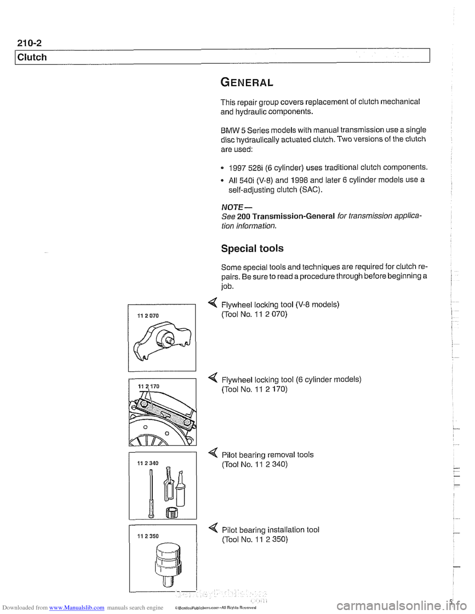
< Flywheel loclting tool (V-8 models)
1 (Tool NO. 11 2 070)
-
4 Flywheel loclting tool (6 cylinder models)
(Tool No. 1 1 2 170)
- < Pilot bearino removal tools
11 11 2350 < pilot bearing instaation
(Tool No. 11 2 350) tool
Page 554 of 1002
Downloaded from www.Manualslib.com manuals search engine
21 0-1 2
Clutch
Release bearing
Release
bearin
- lnspect flywheel for scoring, hot spots, cracks or loose or
worn guide pins. If any faults are found, replace flywheel as
described later.
- lnspect transmission pilot bearing in end of crankshaft. The
bearing should rotate smoothly without play. If necessary,
replace as described later.
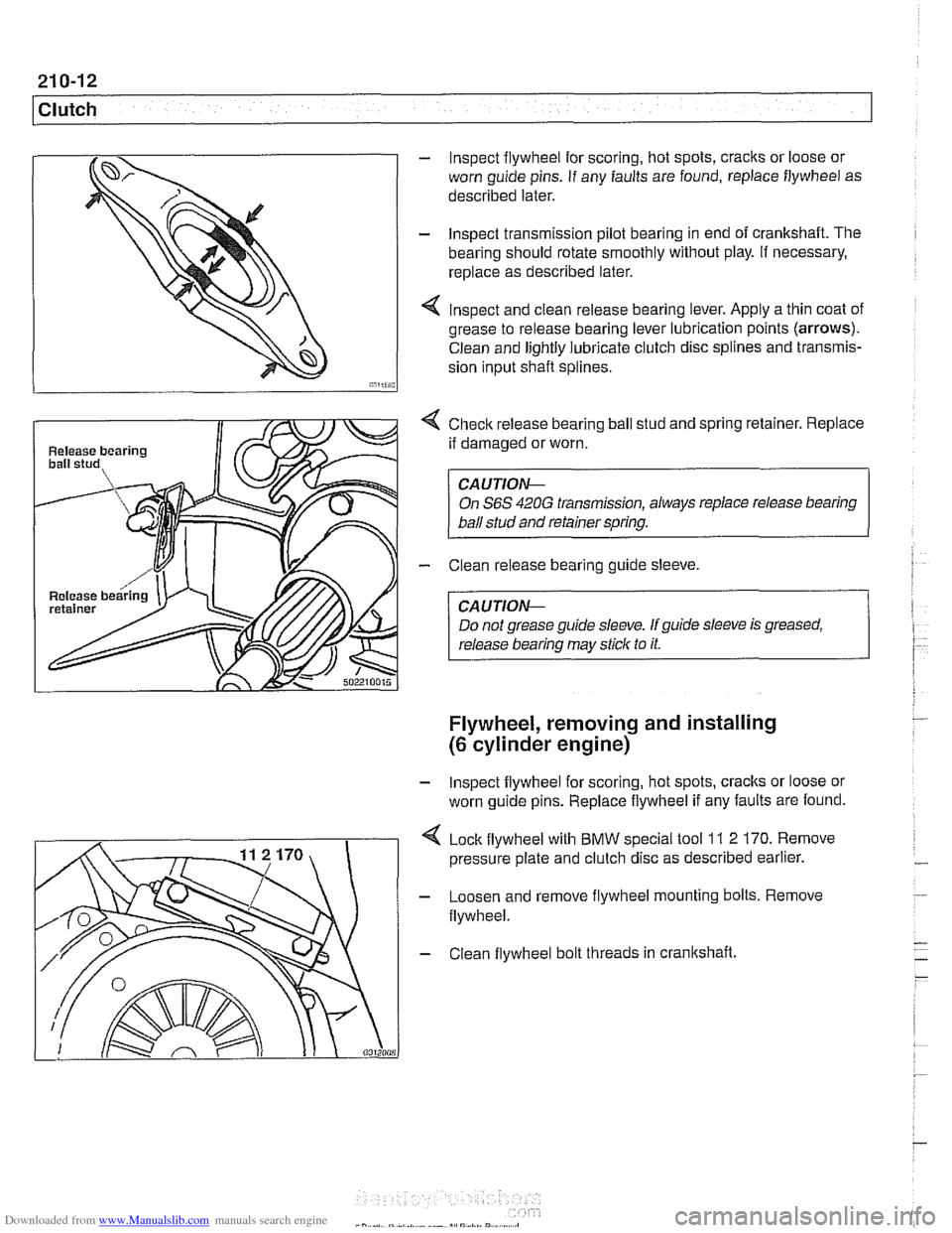
4 lnspect and clean release bearing lever. Apply a thin coat of
grease to release bearing lever lubrication points (arrows).
Clean and lightly lubricate clutch disc splines and transmis-
sion input
shaft splines.
4 Checlc release bearing ball stud and spring retainer. Replace
if damaged or worn.
CAUTION--
On S6S 420G transmission, always replace release bearing
ball stud and retainer spring.
- Clean release bearing guide sleeve.
CA U TIOG
Do not grease guide sleeve. If guide sleeve is greased,
release bearing may stick to it.
Flywheel, removing and installing
(6 cylinder engine)
- lnspect flywheel for scoring, hot spots, cracks or loose or
worn guide pins. Replace flywheel if any faults are found.
Lock flywheel with BMW special tool
11 2 170. Remove
pressure plate and clutch disc as described earlier.
- Loosen and remove flywheel mounting bolts. Remove
flywheel.
- Clean flywheel bolt threads in crankshaft.
Page 557 of 1002
Downloaded from www.Manualslib.com manuals search engine
21 0-1 5
Clutch
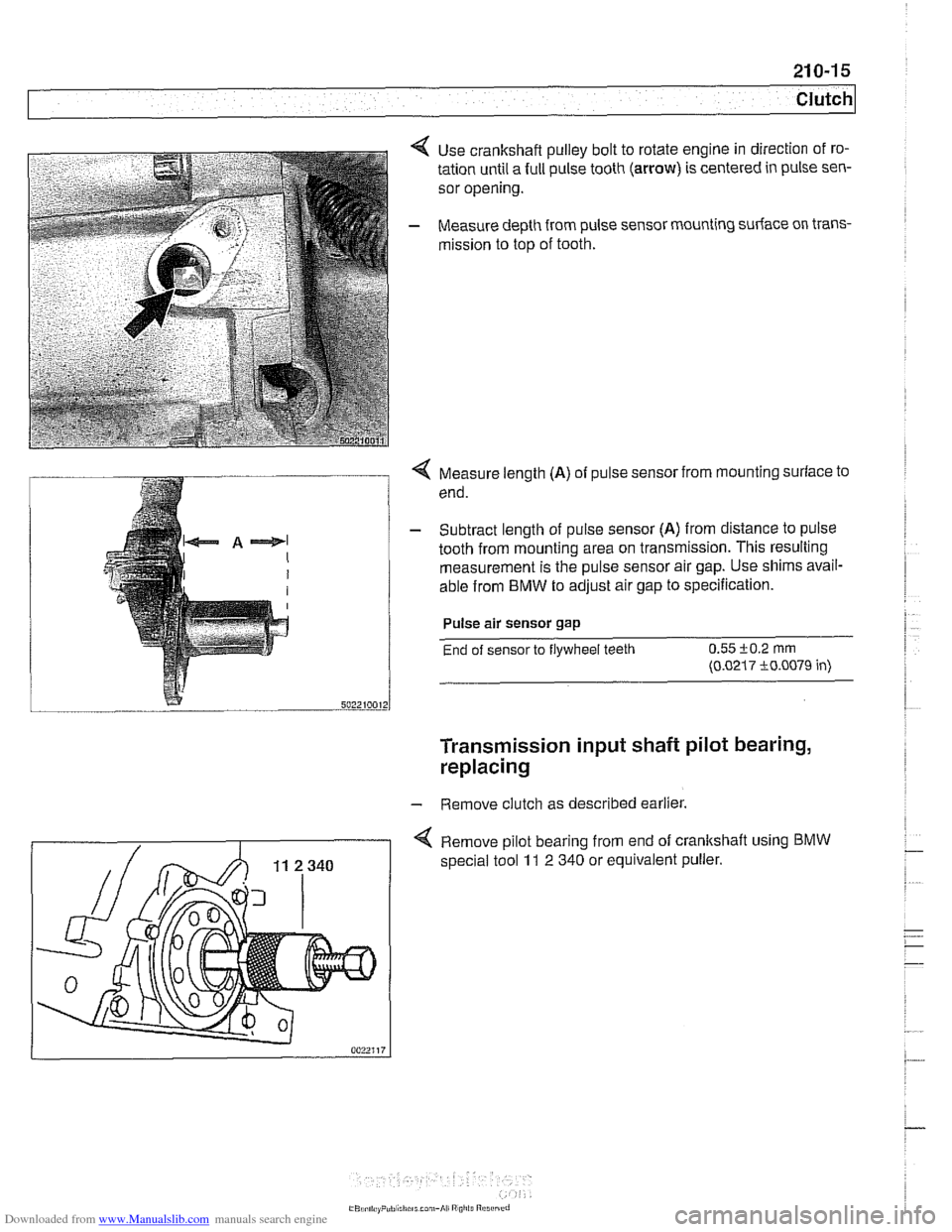
Use crankshaft pulley bolt to rotate engine in direction of ro-
tation until a full pulse tooth
(arrow) is centered in pulse sen-
sor opening.
Measure depth from pulse sensor mounting surface on trans-
mission to top of tooth.
Q Measure length (A) of pulse sensor from mounting surface to
end.
- Subtract length of pulse sensor (A) from distance to pulse
tooth from mounting area on transmission. This resulting
measurement is the pulse sensor air gap. Use shims avail-
able from
BMW to adjust air gap to specification.
Pulse air sensor gap
End of sensor to flywheel teeth 0.55 i-0.2 rnrn
(0.0217 i0.0079 in)
Transmission input shaft pilot bearing,
replacing
- Remove clutch as described earlier.
4 Remove pilot bearing from end of crankshaft using BMW
special tool 11 2 340 or equivalent puller.
Page 558 of 1002
Downloaded from www.Manualslib.com manuals search engine
21 0-1 6
Clutch
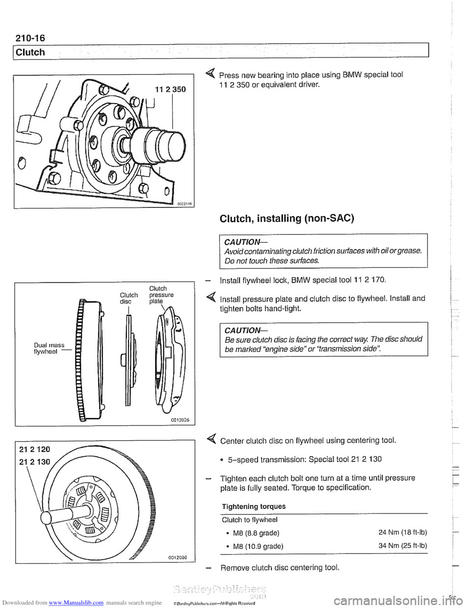
4 Press new bearing into place using BMW special tool
11 2 350 or equivalent driver.
Clutch, installing (non-SAC)
CAUTIOG
Avoidcontaminating clutch friction surfaces with oilorgrease.
Do not touch these surfaces.
4 Center clutch disc on flywheel using centering tool
Clutch Clutch pressure disc plate
Dual mass flywheel -
5-speed transmission: Special tool 21 2 130
- Install flywheel lock, BMW special tool 11 2 170.
4 Install pressure plate and clutch disc to flywheel. Install and
tighten bolts hand-tight.
CAUTIOG
Be sure clutch disc is facing the correct way The disc should
be
marked 'kngine side" or "transmission side':
- Tighten each clutch bolt one turn at a time until pressure
plate is fully seated. Torque to specification.
Tightening torques
Clutch to flywheel
. M8 (8.8 grade) 24 Nrn (18
ft-lb)
- M8 (10.9 grade) 34 Nrn (25 ft-lb)
- Remove clutch disc centering tool.
Page 559 of 1002
Downloaded from www.Manualslib.com manuals search engine
Clutch
- Remove flywheel locking tool
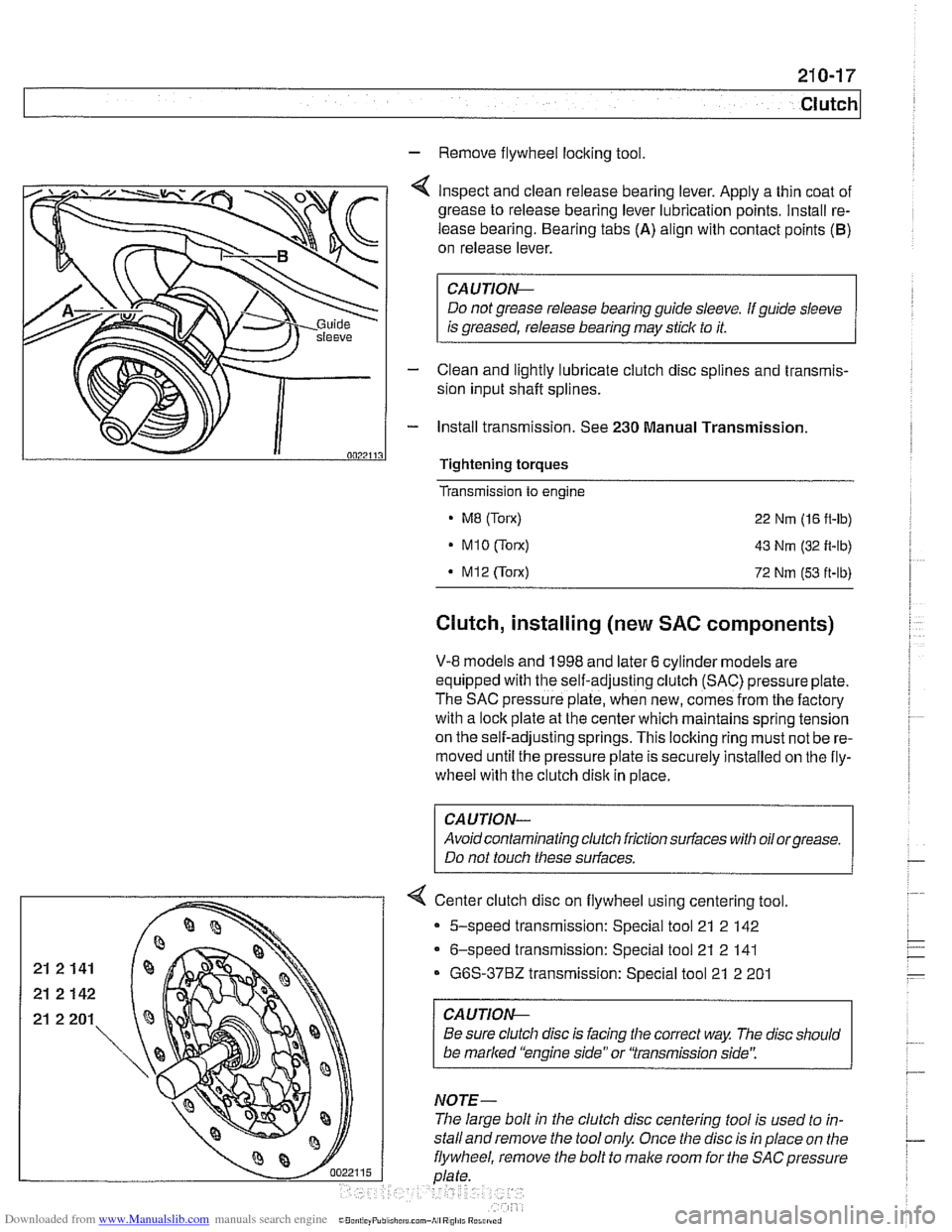
4 Inspect and clean release bearing lever. Apply a thin coat of
grease to release bearing lever lubrication points. Install re-
lease bearing. Bearing tabs
(A) align with contact points (B)
on release lever.
CAUTION-
Do not grease release bearing guide sleeve. If guide sleeve
is greased, release bearing may stick to it.
- Clean and lightly lubricate clutch disc splines and transmis-
sion input shaft splines.
- Install transmission. See 230 Manual Transmission
.
Transmission to engine
MB (Torx) 22 Nm (16 fl-lb)
MlO(Torx) 43 Nm (32 fl-lb)
Clutch, installing (new SAC components)
V-8 models and 1998 and later 6 cylinder models are
equipped with the self-adjusting clutch (SAC) pressure plate.
The SAC pressure plate, when new, comes from the factory
with a lock plate at the center which maintains spring tension
on the self-adjusting springs. This
loclting ring must not be re-
moved until the pressure plate is securely installed on tlie fly-
wheel with the clutch disk in place.
CAUTION-
Avoidcontaminating clutch friction surfaces with oilorgrease.
Do not touch these surfaces.
< Center clutch disc on flywheel using centering tool.
5-speed transmission: Special tool 21 2
142
- 6-speed transmission: Special tool 21 2 141
G6S-3782 transmission: Special tool 21 2 201
CAUTION-
Be sure clutch disc is facing the correct way The disc should
be marked "engine side" or "transmission side':
The large bolt in the clutch disc centering tool is used to
in-
stalland remove the tool only. Once the disc is in place on the
eel, remove the bolt to male room for tlie
SACpressure
Page 560 of 1002
Downloaded from www.Manualslib.com manuals search engine
21 0-1 8
Clutch
- lnstall flywheel lock, special tool 11 2 170 (6 cylinder model)
or
11 2 070 (V-8 model).
- Install SAC pressure plate on dowel pins at flywheel. lnstall
clutch mounting bolts and tighten each one turn at a time until
pressure plate is fully seated. Torque to specification.
Tightening torques Clutch to flywheel
- M8 (8.8 grade)
MB 110.9 orade)
24 Nm (1 8 it-lb)
34 Nm (25
ft-lb)
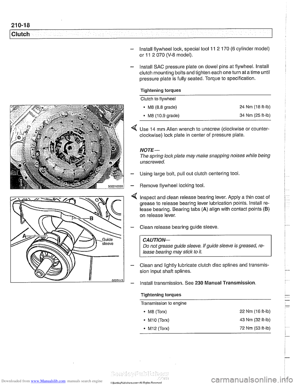
Use 14 mm Allen wrench to unscrew (clocltwise or counter-
clockwise) lock plate in center of pressure plate.
NOTE-
The spring lockplate may make snapping noises while being
unscrewed.
Using large bolt, pull out clutch centering tool
Remove flywheel locking tool
4 Inspect and clean release bearing lever. Apply a thin coat of
grease to release bearing lever lubrication points. lnstall re-
lease bearing. Bearing tabs
(A) align with contact points (B)
on release lever.
- Clean release bearing guide sleeve.
CAUTIOG
Do not grease guide sleeve. Ifguide sleeve is greased, re-
lease bearing may stick to it.
- Clean and lightly lubricate clutch disc splines and transmis-
sion input shaft splines.
- lnstall transmission. See 230 Manual Transmission.
Tightening torques
- - - Transmlsslon to engine -
. MB (Torx) 22
Nm (16 it-lb)
MI0 (Torx) 43 Nm (32 it-lb)
* M12 (Torx) 72 Nm (53 it-lb)
.-
Page 562 of 1002
Downloaded from www.Manualslib.com manuals search engine
1 Clutch
- lnstall flywheel lock, special tool 11 2 170 (6 cylinder model)
or
11 2 070 (V-8 model).
- lnstall SAC pressure plate on dowel pins at flywheel. lnstall
clutch mounting bolts and tighten each one turn at a time until
pressure plate is fully seated. Torque to specification.
Tightening torques
Clutch to flywheel
- M8 (8.8 grade)
M8 (10.9 grade) 24
Nm (18
ft-ib)
34
Nm (25 ft-lb)
- Slip out clutch centering tool using large bolt.
- Remove flywheel locking tool.
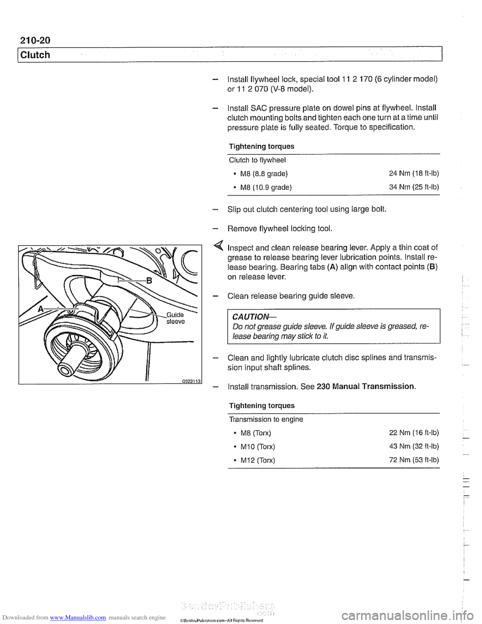
Inspect and clean release bearing lever. Apply a thin coat of
grease to release bearing lever lubrication points. lnstall re-
lease bearing. Bearing tabs
(A) align with contact points (B)
on release lever.
- Clean release bearing guide sleeve.
CA U TIOG
Do not grease guide sleeve. If guide sleeve is greased, re-
lease bearing may stick to it.
- Clean and lightly lubricate clutch disc splines and transmis-
sion input shaft splines.
- Install transmission. See 230 Manual Transmission
Tightening torques
Transmission to engine
- ME (Torx)
. M1O (Torx)
. M12 (Torx) 22
Nm (16 ft-lb)
43
Nm (32 ft-lb)
72
Nm (53 it-lb)
Page 609 of 1002
Downloaded from www.Manualslib.com manuals search engine
Driveshaft
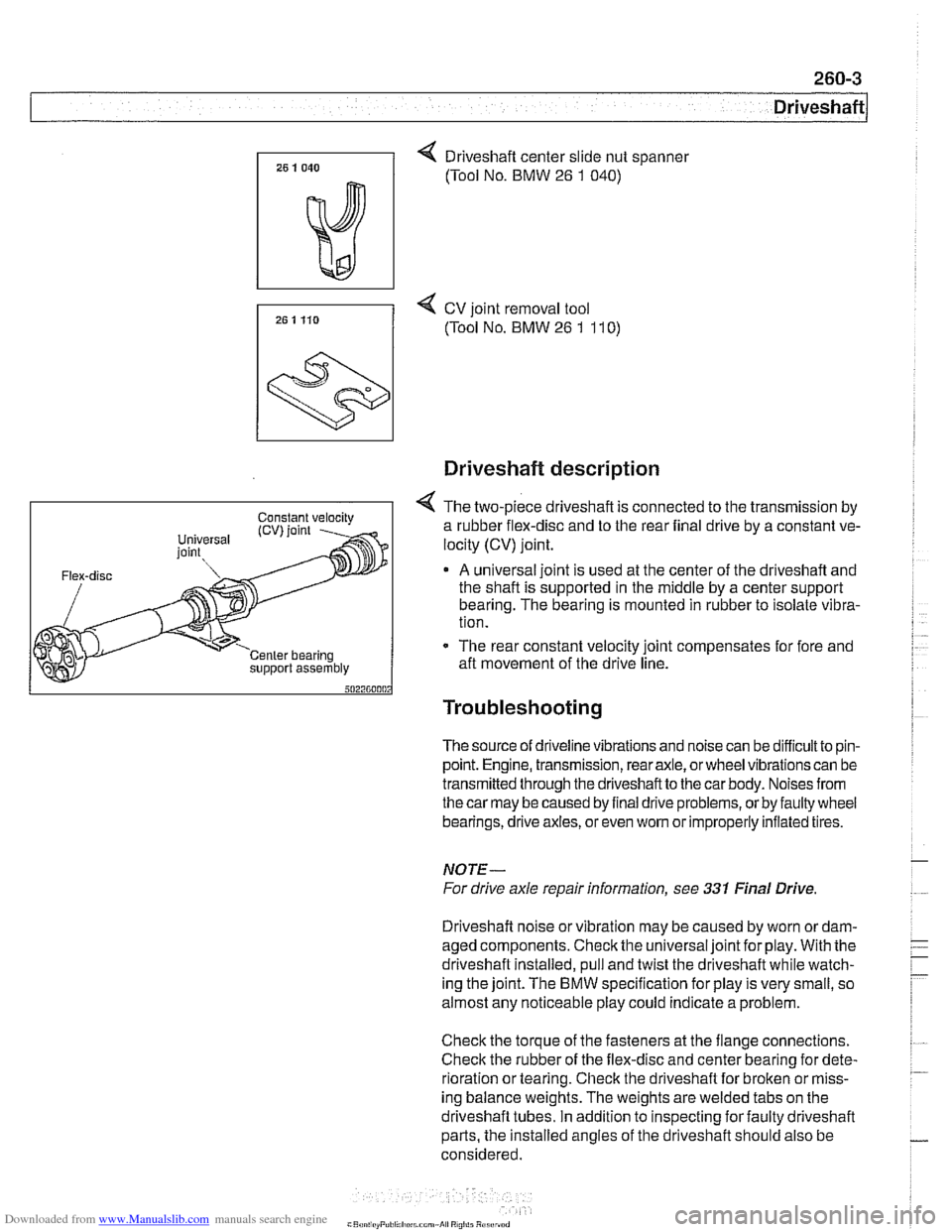
4 Driveshaft center slide nut spanner
(Tool No. BMW
26 1 040)
7, 25 1 Ho 4 cv joint removal tool
(Tool No. BMW 26 1 11 0)
support assembly
Driveshaft description
4 The two-piece driveshaft is connected to the transmission by
a rubber flex-disc and to the rear final drive by a constant ve-
locity (CV) joint.
A universal joint is used at the center of the driveshaft and
the shaft is supported in the middle by a center support
bearing. The bearing is mounted in rubber to isolate vibra-
tion.
- The rear constant velocity joint compensates for fore and
aft movement of the drive line.
Troubleshooting
The source of driveline vibrations and noise can be difficultto pin-
point. Engine, transmission, rear axle, or wheel vibrations can be
transmitted through thedriveshaftto the car body. Noises from
thecar may be caused by final drive problems, or by faulty wheel
bearings, drive axles, or even
wom or improperly inflated tires.
NOTE-
For drive axle repair information, see 331 Final Drive
Driveshaft noise or vibration may be caused by worn
ordam-
aged components. Check the universal joint for play. With the
driveshaft installed, pull and twist the driveshaft while watch-
ing the joint. The
BMW specification for play is very small, so
almost any noticeable play could indicate a problem.
Check the torque of the fasteners at the flange connections.
Check the rubber of the flex-disc and center bearing for dete-
rioration or tearing. Check the driveshaft for broken or miss-
ing balance weights. The weights are welded tabs on the
driveshaft tubes. In addition to inspecting for faulty driveshaft
parts, the installed angles of the driveshaft should also be
considered.
Page 622 of 1002
Downloaded from www.Manualslib.com manuals search engine
[~us~ension, Steering and Brakes - General
This section of the manual covers front and rear suspension,
braking and steering systems, and contains wheel, tire and
wheel alignment information and specifications. Also covered
here are the integrated braking and suspension systems in-
cluding
antilock braking (ABS), traction control (ASCIDSC),
and electronic height control (EHC).
Vehicle ride height information is at the end of this repair
group. Alignment information is in
320 Steering and Wheel
Alignment.
Aluminum suspension components
In order to reduce vehicle weight, aluminum suspension com-
ponents are used in some models. A test with a magnet will
easily reveal the metal used. If working with aluminum com-
ponents, be sure to read and follow the cautions below.
CAUTION-
* Due to the chemical and corrosion characteristics of alumi-
num, do not bring into contact with battery acid.
Do not use wire brushes with brass or iron bristles.
Only use brushes with stainless steel bristles.
Do not expose to flying sparks from
grinding/cutting op-
erations.
Do not subject to steel welding splashes.
Do not expose to temperatures over
80°C (176"F),
even for short periods. Temperatures in painting facili-
ties are not a problem.
The E39 front suspension subframe is used as a rigid mount-
ing platform for the front suspension arms, stabilizer bar and
steering gear.
The suspension arms, known as the lower control arms and
the tension struts (thrust arms), are connected to the
sub-
frame through rubber bushings. The arms are connected to
the steering
knucltles in a double pivot configuration.
Each front strut assembly includes a tubular strut and a coil
spring. The upper strut mount includes a bearing. The lower
end of each strut housing is fitted to the steering knuckle. The
integral wheel bearing and hub are bolted to the steering
Iknucltle.
6-cylinder and V-8 models use different steering systems and
other front suspension components.