Torque wrench BMW 528i 1998 E39 User Guide
[x] Cancel search | Manufacturer: BMW, Model Year: 1998, Model line: 528i, Model: BMW 528i 1998 E39Pages: 1002
Page 178 of 1002
Downloaded from www.Manualslib.com manuals search engine
This group covers cylinder head and valvetrain service and
repair. Some of the repair procedures described here require
that the cylinder head first be removed as described in
113
Cylinder Head Removal and Installation.
NOTE- For timing chain and
VANOS repair information, see 117
Camshaft Timing Chain.
If it is
determined that the cylinder head will require signif-
icant reconditioning work, a remanufactured cylinder head
may be a good alternative. Remanufactured cylinder
heads are available from an authorized
BMW dealer.
The information given in this repair group is organized ac-
cording to engine code. For engine application information,
see
I00 Engine-General.
For specific repair procedures, refer to the appropriate repair
group:
* 020 Maintenance
100 Engine-General
113 Cylinder Head Removal and Installation
117 Camshafi Timing Chain
= 170 Radiator and Coo!ing System
Special Tools
Special BMW tools are required for most cylinder head ser-
vice described in this repair group. Many of these tools are ex-
pensive and only available through an authorized
BMW
dealer. If the special tools are not available, have the cylinder
head removed and disassembled by an authorized BMW
dealer. Be sure to read each procedure thoroughly before
starting a job to determine which special tools and equipment
will be necessary.
Most of the repairs to a cylinder head require precision
rna-
chine work to specific tolerances. This type of work should be
performed by an authorized BMW repairfacility or an ASE
certified machinist.
71 Torque wrench with flex shaft
Page 238 of 1002
Downloaded from www.Manualslib.com manuals search engine
1 17-2
Camshaft Timing Chain
This repair group covers timing chain and VANOS repair
information for the following engines:
M52 (Single VANOS 6-cylinder engine)
M52
TU and M54 (Double VANOS engines)
M62 (Non VANOS
V-8 engine)
NOTE-
The M62 TU V-8 engine with VANOS Variable Camshaft
Timing repair information is not included.
NOTE-
See 100 Engine General for engine code and application
information.
Worn timing chains and sprocltets can lead to noisy operation
and erratic valve timing. Afaulty tensionercan also cause tim-
ing chain noises.
For specific repair procedures, refer to the appropriate repair
group:
020 Maintenance
113 Cylinder Head Removal and Installation
119 Lubrication System
121 Ignition System
170 Radiator and Cooling System
Special tools
Special BMW service tools are needed to perform the service
and repairs procedures covered in this repair group. Many of
these tools are expensive and only available through an au-
thorized BMW dealer. Be sure to read each procedure thor-
oughly before starting a job to determine which special tools
will be necessary.
In addition, Double VANOS system diagnosis can only be
carried out by using BMW specific electronic scan tools, such
as BMW
DISplus, MoDiC or equivalent.
4 Torque wrench wl flex extension
(Tool No. BMW 00
9 250)
Page 245 of 1002
Downloaded from www.Manualslib.com manuals search engine
Camshaft Timing Chain
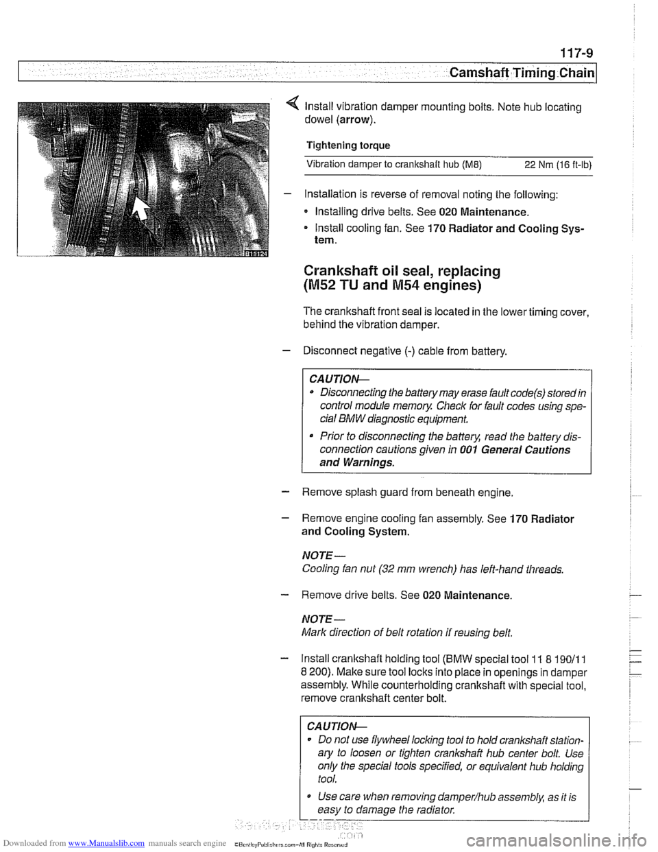
lnstall vibration damper mounting bolts. Note hub locating
dowel (arrow).
Tightening torque
Vibration damper to crankshaft hub
(ME) 22 Nm (16 ft-lb)
- Installation is reverse of removal noting the following:
Installing drive belts. See 020 Maintenance.
Install cooling fan. See 170 Radiator and Cooling Sys-
tem.
Crankshaft oil seal, replacing
(M52 TU and M54 engines)
The crankshafl front seal IS located in the lower timing cover,
behind the
vibrat~on damper.
- Disconnect negative (-) cable from battery.
Disconnecting the battery may erase fault
code(s) storedin
control module memoy Checlc for fault codes using spe-
cial
BMW diagnostic equipment.
Prior to disconnecting the battery, read the battery dis-
connection cautions given in
001 General Cautions
and Warnings.
- Remove splash guard from beneath engine
- Remove engine cooling fan assembly. See 170 Radiator
and Cooling System.
NOTE- Cooling fan nut
(32 mm wrench) has left-hand threads.
- Remove drive belts. See 020 Maintenance
NOTE-
Mark direction of belt rotation if reusing belt.
- Install crankshaft holding tool (BMW special tool 11 8 19011 1
8 200). Make sure tool locks into place in openings in damper
assembly. While counterholding crankshafl with special tool,
remove crankshaft center bolt.
CAUTIOI\C
Do not use flywheel locling tool to hold crankshaft station-
ary to loosen or tighten
cranl(shaft hub center bolt. Use
only the special tools specified, or equivalent hub holding
tool.
Use care when removing
damper/hub assembly, as ~t is
easy to damage the radiator
Page 247 of 1002
![BMW 528i 1998 E39 User Guide Downloaded from www.Manualslib.com manuals search engine
Camshaft Timing chain]
4 Coat new seal with oil and position in timing chain cover. Use
BMW special tool 11
3 280 and crankshaft center BMW 528i 1998 E39 User Guide Downloaded from www.Manualslib.com manuals search engine
Camshaft Timing chain]
4 Coat new seal with oil and position in timing chain cover. Use
BMW special tool 11
3 280 and crankshaft center](/img/1/2822/w960_2822-246.png)
Downloaded from www.Manualslib.com manuals search engine
Camshaft Timing chain]
4 Coat new seal with oil and position in timing chain cover. Use
BMW special tool 11
3 280 and crankshaft center bolt to draw
seal in flush with timing case cover.
- Align vibration damper assembly with keyway and tap into
place. Insert new center bolt with washer.
CA
UTIOG
Inspect woodruff key for damage before installing hub
assembly.
- Install crankshaft holding tool malting sure tool locks into
place in openings in damper assembly. While counterholding
cranltshaft, tighten crankshaft center bolt.
- Attach special tools 11 8 20011 1 8 190 to damper assembly.
Counterhold damper with 11 8 190 while tightening center
bolt.
Tightening
torque
Vibration damper hub to crankshaft 410 Nm (302 it-ib)
- Installation is reverse of removal noting the following:
Install drive belts. See 020 Maintenance.
Install cooling fan. See 170 Radiator and Cooling Sys-
tem.
Crankshaft oil seal, replacing
(M62 and M62 TU engines)
- Disconnect negative (-) cable from battery
CAUTIOG
Disconnecting the battery may erase fault code(s) storedin
control module memory. Check for fault codes using spe-
cial BMW diagnostic equipment.
* Prior to disconnecting the battery, read the battery dis-
connection cautions in
001 General cautions and
warnings.
- Remove splash guard from beneath engine
- Remove engine cooling fan assembly. See 170 Radiator
and Cooling System.
NOTE
-
Cooling fan nut (32 mm wrench) has left-hand threads.
- Remove drive belts. See 020 Maintenance.
NOTE-
Marlc direction of belt rotation if reusing belt.
Page 305 of 1002
Downloaded from www.Manualslib.com manuals search engine
-
Camshaft Timing chain1
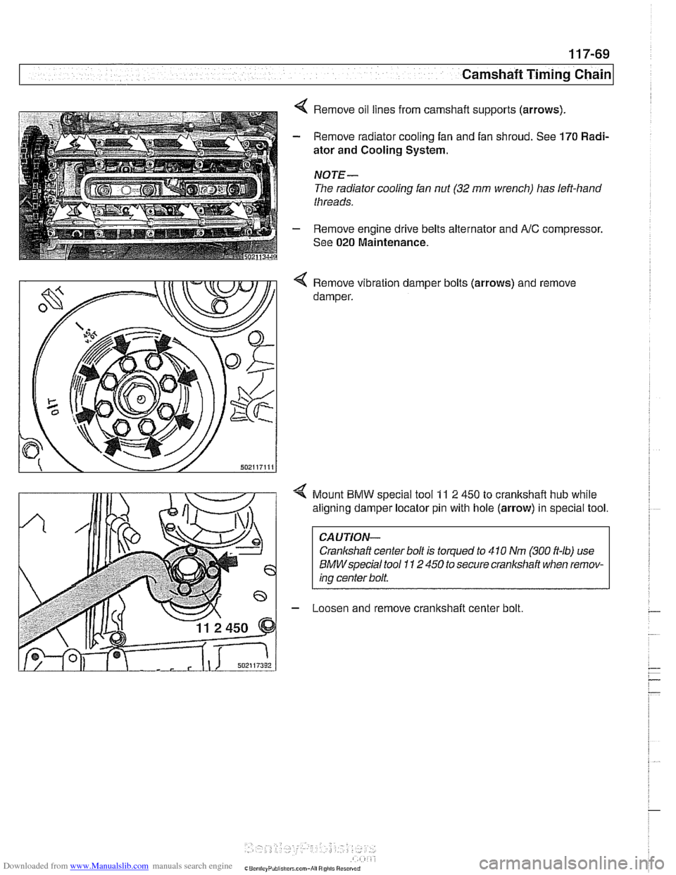
4 Remove oil lines from camshaft supports (arrows).
- Remove radiator cooling fan and fan shroud. See 170 Radi-
ator and Cooling System.
NOTE-
The radiator cooling fan nut (32 mm wrench) has left-hand
threads.
- Remove engine drive belts alternator and AlC compressor.
See
020 Maintenance.
4 Remove vibration damper bolts (arrows) and remove
damper.
4 Mount BMW special tool 11 2 450 to crankshaft hub while
aligning damper locator pin with hole (arrow) in special tool.
CAUTION-
Crankshaft center bolt is torqued to 410 Nm (300 ft-lb) use
BMWspecial tool I I 2 450 to secure crankshaft when remov-
ing center bolt.
- Loosen and remove cranltshaff center bolt.
Page 318 of 1002
Downloaded from www.Manualslib.com manuals search engine
[camshaft Timina Chain Cylinders
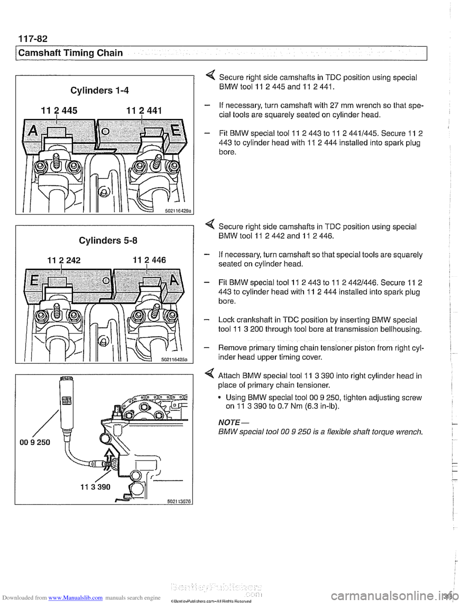
1-4
11 2445 11 2 441
502116429;
Secure right side camshafts in TDC position using special
BMWtoolll 2445andll 2441.
- If necessary, turn camshaft with 27 mm wrench so that spe-
cial tools are squarely seated on cylinder head.
- Fit BMW special tool 11 2 443 to 11 2 4411445. Secure 11 2
443
to cylinder head with 11 2 444 installed into spark plug
bore.
I
< Secure right side camshafts in TDC position using special
Cylinders 5-8 BMW tool 11 2 442 and 11 2 446.
- If necessary, turn camshaft so that special tools are squarely
seated on cylinder head.
- Fit BMW special tool 11 2 443 to 11 2 4421446. Secure 11 2
443
to cylinder head with 11 2 444 installed into spark plug
bore.
- Lock cranltshaft in TDC position by inserting BMW special
tool
11 3 200 through tool bore at transmission bellhousing.
- Remove primary timing chain tensioner piston from right cyl-
~nder head upper timing cover.
4 Attach BMW special tool 11 3 390 into right cylinder head in
place of primary chain tensioner.
Using BMW special tool
00 9 250, tighten adjusting screw
on
11 3 390 to 0.7 Nm (6.3 in-lb).
NOTE-
BMW special fool 00 9 250 is a flexible shaft torque wrench.
Page 346 of 1002
Downloaded from www.Manualslib.com manuals search engine
11 9-26
/Lubrication System
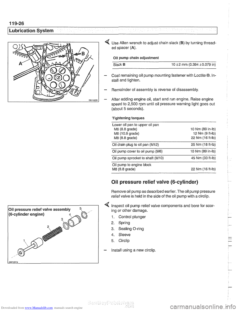
< Use Allen wrench to adjust chain slaclc (B) by turning thread-
ed spacer
(A).
Oil pump chain adjustment
Slack
10 52 mrn (0.394i0.079 in)
- Coat remaining oil pump mounting fastener with Loctite 03. In-
stall and tighten.
- Remainder of assembly is reverse of disassembly.
- After adding engine oil, start and run engine. Raise engine
speed to
2,500 rpm until oil pressure warning light goes out
(about
5 seconds).
Tightening torques
Lower oil pan to upper oil pan
M6 (8.8 grade) 10
Nm (89 in-ib)
M6 (10.9 grade) 12
Nm (9 ft-lb)
M8 (8.8 grade) 22
Nrn (1 6 ft-lb)
Oil drain plug to oil pan (M12) 25 Nm (I8 ft-lb)
Oil pump cover to oil pump
(M6) 10 Nrn (89 in-lb)
Oilpump sprocket to shaft TKO) 45 Nm (33 it-lb)
Oil pump to engine bloclc
M8 (8.8 grade) 22 Nrn (16 ft-lb)
Oil pressure relief valve (&cylinder)
Remove oil
pump as described earlier. The oil pump pressure
relief valve is held in the side of the
oil pump with a circlip.
< Inspect oil pump relief valve components and bore for scor-
4. Sleeve
5. Circlip
- Install using a new circlip.
Oil
pressure relief valve assembly
,- ..., !~. -.-~. - ~- -~!~~-% h. .- .,, /to-cy~~noer engrnej ing or other damage.
1. Control plunger
2. Spring
3. Sealing O-ring
Page 364 of 1002
Downloaded from www.Manualslib.com manuals search engine
120-1 6
Ignition System
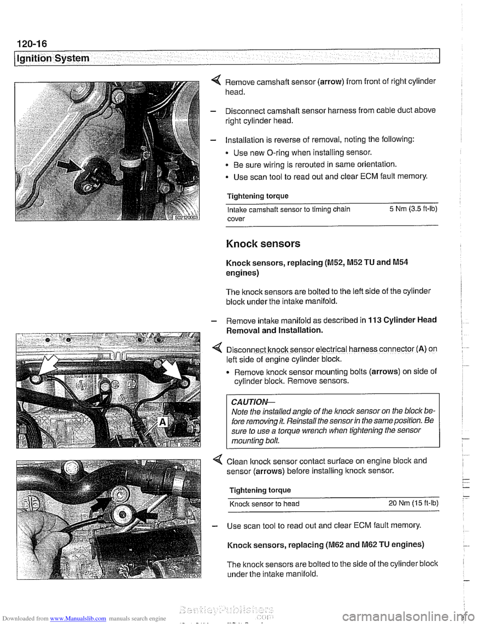
Remove camshaft sensor (arrow) from front of right cylinder
head.
Disconnect camshaft sensor harness from cable duct above
right cylinder head.
Installation is reverse of removal, noting the following:
Use new O-ring when installing sensor.
Be sure wiring is rerouted in same orientation.
Use scan tool to read out and clear ECM fault memory.
Tightening torque Intake camshaft sensor to timing chain 5 Nm
(3.5 ft-lb)
cover
Knock sensors
Knock sensors, replacing (M52, M52 TU and M54
engines)
The knock sensors are bolted to the left side of the cylinder
block under the intake manifold.
- Remove intalte manifold as described in 113 Cylinder Head
Removal and Installation.
D~sconnect knock sensor electrical harness connector (A) on
left side of engine cylinder block.
Remove knock sensor
mount~ng bolts (arrows) on side of
cyllnder block. Remove sensors.
Note the installed angle of the
lnocl~ sensor on the bloc/( be-
fore removing it. Reinstall the sensor
in the same position. Be
sure to use a torque wrench when tightening the sensor
mounting bolt.
< Clean lknock sensor contact surface on engine bloclc and
sensor (arrows) before installing
ltnock sensor.
Tightening torque
Knock sensor to head 20 Nm (15 ft-lb)
- Use scan tool to read out and clear ECM fault memory.
Knock sensors, replacing
(M62 and M62 TU engines)
The
knock sensors are bolted to the side of the cylinder block
under the
intake manifold.
Page 365 of 1002
Downloaded from www.Manualslib.com manuals search engine
Ignition System
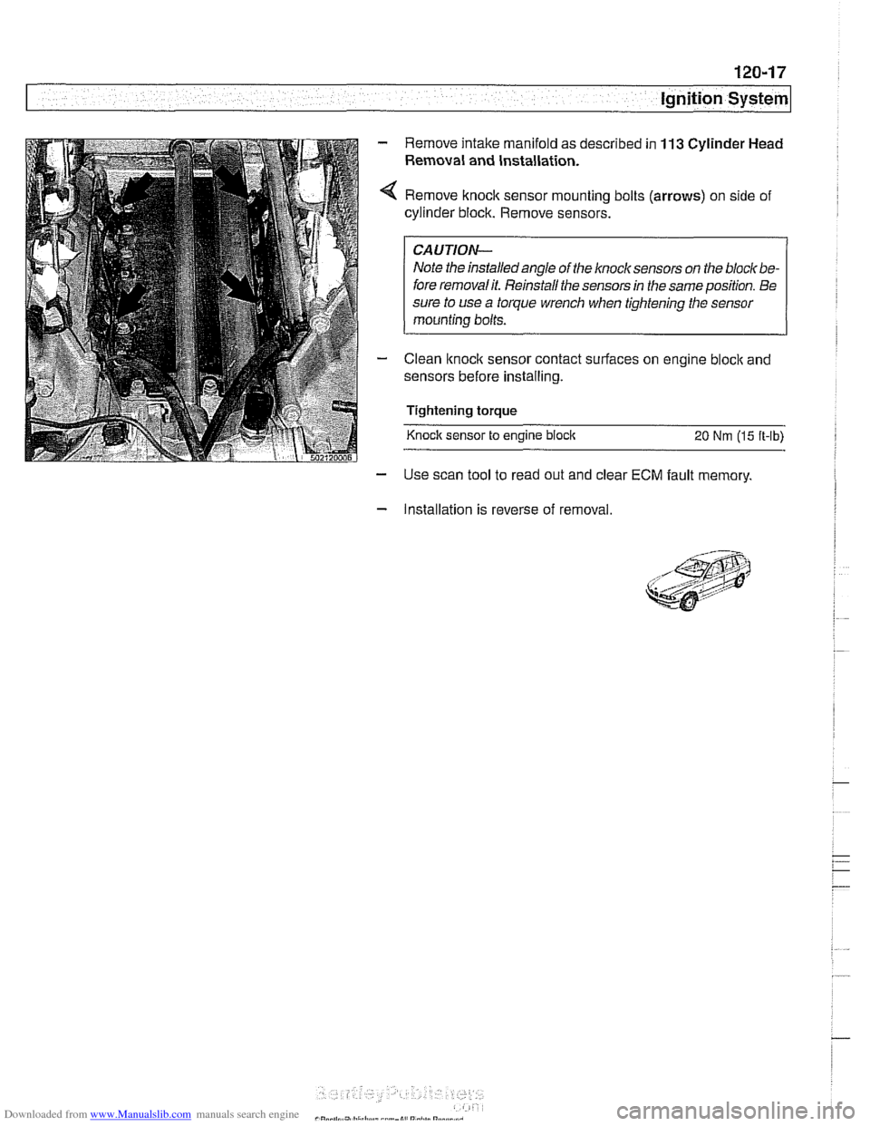
Remove intake manifold as described in 113 Cylinder Head
Remaval and Installation.
Remove knock sensor mounting bolts (arrows) on side of
cylinder block. Remove sensors.
I CAUTION- I
Note the installedangle of the knock sensors on the bloclt be-
fore removalit. Reinstall the sensors in the same position. Be
sure to use
a torque wrench when tightening the sensor
mounting bolts.
Clean
lknoclc sensor contact surfaces on engine bloclc and
sensors before installing.
Tightening torque
Knock sensor to engine
bloclc 20 Nm (15 ft-lb)
- Use scan tool to read out and clear ECM fault memory.
- Installation is reverse of removal.
Page 511 of 1002
Downloaded from www.Manualslib.com manuals search engine
Radiator and Cooling System
Remove rubber trim strip between top of shroud and radiator.
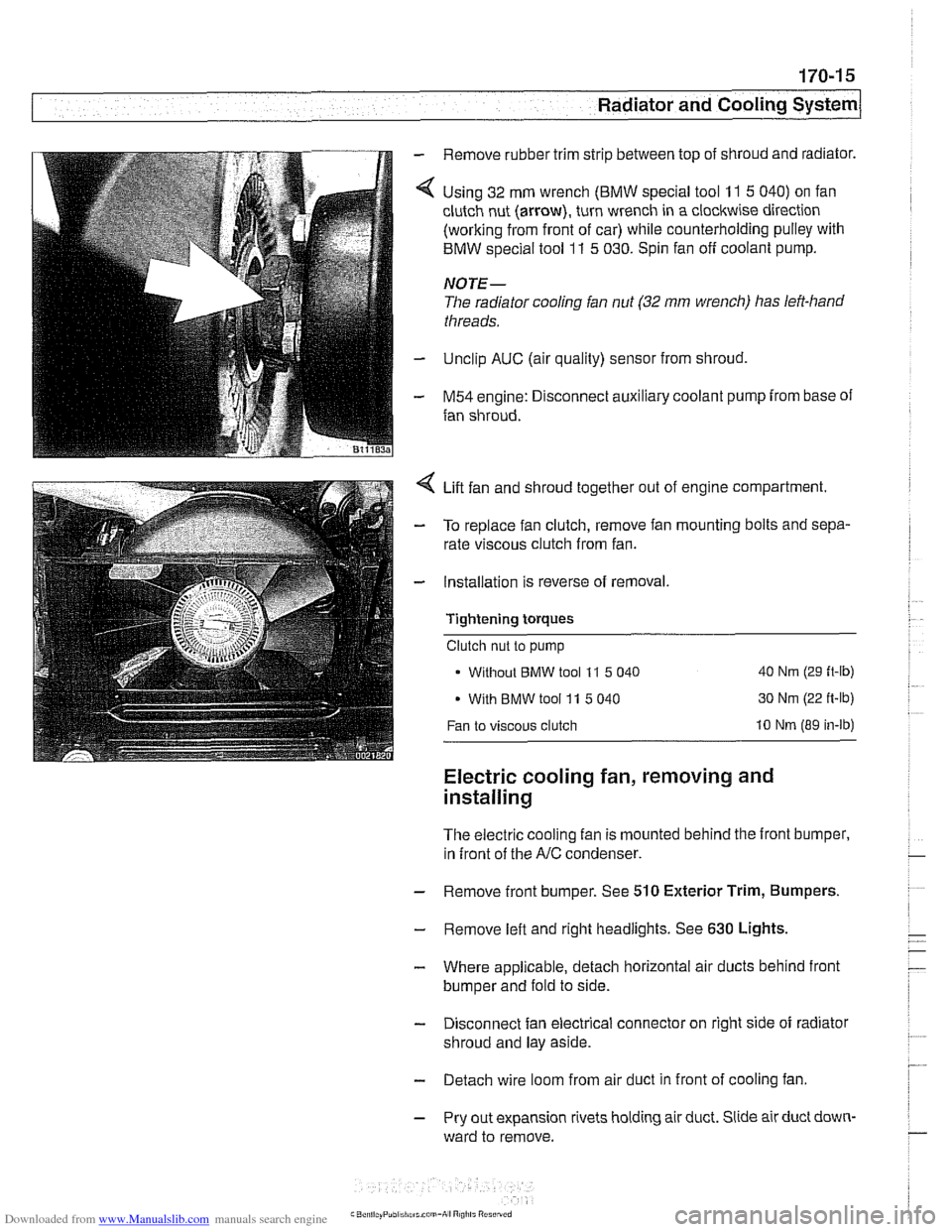
Using 32 mm wrench
(BMW special tool 11 5 040) on fan
clutch nut (arrow), turn wrench in a clockwise direction
(working from front of car) while counterholding pulley with
BMW special tool
11 5 030. Spin fan off coolant pump.
NOTE-
The radiator cooling fan nut (32 mm wrench) has left-hand
threads.
Unclip AUC (air quality) sensor from shroud,
M54 engine: Disconnect auxiliary coolant pump from base of
fan shroud.
Lift fan and shroud together out of engine compartment.
To replace fan clutch, remove fan mounting bolts and sepa-
rate viscous clutch from fan.
Installation is reverse of removal.
Tightening
torques
Clutch nut to pump
Without
BMW tool 11 5 040 40 Nm (29 ft-lb)
With BMW tool 11 5 040 30 Nm
(22 ft-lb)
Fan to viscous clutch 10 Nm (89 in-lb)
Electric cooling fan, removing and
installing
The electric cooling fan is mounted behind the front bumper,
in front of the
A/C condenser.
- Remove front bumper. See 510 Exterior Trim, Bumpers.
- Remove left and right headlights. See 630 Lights,
- Where applicable, detach horizontal air ducts behind front
bumper and fold to side.
- Disconnect fan electrical connector on right side of radiator
shroud and lay aside.
- Detach wire loom from air duct in front of cooling fan
- Pry out expansion rivets holding air duct. Slide air duct down-
ward to remove.