electrical system general BMW 528i 1998 E39 Owner's Manual
[x] Cancel search | Manufacturer: BMW, Model Year: 1998, Model line: 528i, Model: BMW 528i 1998 E39Pages: 1002
Page 462 of 1002
Downloaded from www.Manualslib.com manuals search engine
130-72
Fuel Injection
I Oxygen sensors, replacing
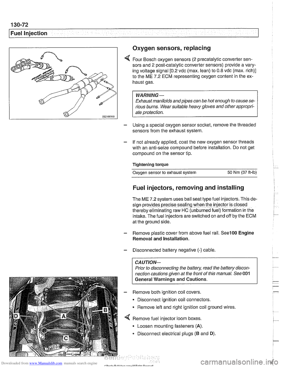
4 Four Bosch oxygen sensors (2 precatalytic converter sen-
sors and
2 post-catalytic converter sensors) provide a vary-
ing voltage signal
[0.2 vdc (max. lean) to 0.8 vdc (max. rich)]
to the ME
7.2 ECM representing oxygen content in the ex-
haust gas.
WARNING-
Exhaust manifolds and pipes can be hot enough to cause se-
rious burns. Wear suitable heavy gloves and other appropri-
ate protection.
- Using a special oxygen sensor socltet, remove the threaded
sensors from the exhaust system.
- If not already applied, coat the new oxygen sensor threads
with an anti-seize compound before installation. Do not get
compound on the sensor tip.
Tightening torque
Oxygen sensor to exhaust system
50 Nm (37 ft-lb)
Fuel injectors, removing and installing
The ME 7.2 system uses ball seat type fuel injectors. This de-
sign
prov:des precise seal'ng when the iniector is closed
therebv eiminalinq raw HC (unb~rned fue ) formalion in tne
intake.-~he fuel inkctors areswitched on and off by the ECM
at the ground side.
- Remove plastic cover from above fuel rail. See100 Engine
Removal and Installation.
- Disconnected battery negative (-) cable.
CAUTION-
Prior to disconnecting the battea read the battery discon-
nection cautions given at the front of this manual. See 001
General Warnings and Cautions.
- Remove both ignition coil covers.
Disconnect ignition coil connectors.
Remove left and right ignition coil ground wires,
4 Remove fuel injector loom boxes.
Loosen mounting fasteners
(A).
Disconnect electrical plugs (B and D).
Page 471 of 1002
Downloaded from www.Manualslib.com manuals search engine
160 Fuel Tank and Fuel Pump
General ........................... .I6 0.2
Special tools ........................ .I6 0.2
Fuel pump ......................... .I6 0.3
Fuel tank evaporative control system ..... .I6 0.3
Evaporative system troubleshooting ..... .I6 0.4
Warnings and cautions ................ .I6 0.5
Fuel System Troubleshooting ...... .I6 0.6
Fuel pump fuse and relay .............. .I6 0.6
Operating fuel pump for tests ........... .I6 0.6
Fuel pump electrical circuit, testing ...... .I6 0.7
Fuel pump power consumption, testing ... .I6 0.9
Fuel pressure gauge, installing
(6-cylinder models)
................. .I6 0.1 0
Fuel pressure gauge, installing
(V-8 models) ....................... .I6 0.1 1
Fuel delivery, testing ................ .I6 0.12
Fuel Pump and Fuel Level Sender . . 160-15
Fuel level sender (right side) and
fuel pump. removing and installing
...... 160-15
Fuel level sender (left side).
removing and installing
............... 160-17
Siphon pump. removing and installing .... 160-1 9
Fuel Tank and Fuel Lines .......... 160-20
Fuel tank. draining ................... 160-20
Fuel tank. removing and installing ....... 160-21
Fuel expansion tank. removing
and installing
....................... 160-23
Activated carbon canister I fuel tank
leak detection unit
(LDP or DMTL).
removing and installing ............... 160-24
Running losses (312-way) valve.
removing and installing
............... 160-24
Page 475 of 1002
Downloaded from www.Manualslib.com manuals search engine
Fuel Tank and Fuel Pump
Warnings and cautions
Observe the following warnings and cautions when servicing
the fuel system.
WARNING-
* The fuel system is designed to retain pressure even when
the ignition is off. When working with the fuelsystem, loos-
en the fuel lines slowly to allow residual
fuel pressure to
dissipate. Avoid spraying fuel. Use shop rags to capture
leaking fuel.
Before beginning any work on the fuel system, place a
fire extinguisher in the vicinity of the work area.
Fuel is highly flammable. When working around fuel, do
not disconnect any wires that could cause electrical
sparks. Do not smoke or worknearheaters or other fire
hazards.
* Always unscrew the fuel tank cap to release pressure
in the
tanlc before working on the tank or lines.
When disconnecting a fuel hose, wrap shop rag around
end of hose to prevent spray of fuel under pressure.
Do not use a work light with an incandescent bulb near
any fuel. Fuel may spray on the hot bulb causing a fire.
0 Make sure the worlc area is properly ventilated.
CAUTION-
- Prior to disconnecting the battery, read the battery discon-
nection cautions given in
001 General Cautions an4
Warnings.
Before
making any electrical tests with the ignition
turned on, disable the ignition system as described in
120 Ignition System. Be sure the battery is discon-
nected when replacing components.
To prevent damage to the ignition system or other DME
components, including the engine control module
(ECM), always connect and disconnect wires and test
equipment with the ignition off.
Cleanliness is essential when
worl~ing with the fuel sys-
tem. Thoroughly clean the fuel line unions before dis-
connecting any of the lines.
Use only clean tools. Keep removed parts clean and
sealed or covered with a clean, lint-free cloth, especial-
ly if completion of the repair is delayed.
Do not move the car while the fuel system is open.
Avoid using high pressure compressed air to blow out
lines and components. High pressure can rupture inter-
nal seals and gaskets.
Always replace seals, O-rings and hose clamps.
Page 491 of 1002
Downloaded from www.Manualslib.com manuals search engine
Fuel Tank and Fuel pump/
- Remove suction hose from tank filler neck carefully to avoid
damaging filler neck baffle plate.
CAUTION-
After finishing repairs but before starling engine, be sure
there is at least
5 liters (1.5 gallons) of fuel in tanlc. The fuel
pump will be damaged if run without fuel.
Fuel tank, removing and installing
- Remove fuel tank filler cap and drain tank as described
earlier.
- Disconnect negative cable from battery.
CAUTION-
Prior to disconnecting the battea read the battery discon-
nection cautions given in
001 General Cautions and
Warnings.
- Remove rear seat bottom cushion. Peel forward lip of carpet
from beneath seat cushion and carefully peel back insulation
to expose fuel tank access cover on left and right sides. Re-
move covers.
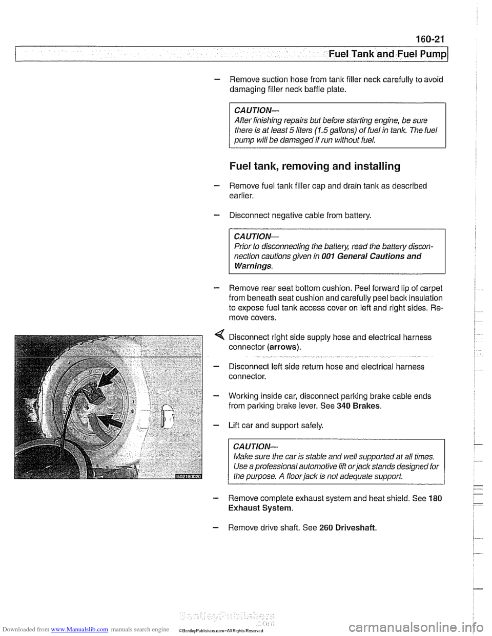
Disconnect right side supply hose and
electr~cal harness
connector (arrows).
D~sconnect left side return hose and electrical harness
connector.
Working inside car, disconnect parking
bralte cable ends
from parking brake lever. See
340 Brakes.
Lift car and support safely.
Make sure the car is stable and
we/ supported at all times.
Use a professional automotive lift
orjack stands designed for
the purpose. A floorjaclc is not adequate support.
- Remove complete exhaust system and heat shield. See 180
Exhaust System.
- Remove drive shaft. See 260 Driveshaft
Page 497 of 1002
Downloaded from www.Manualslib.com manuals search engine
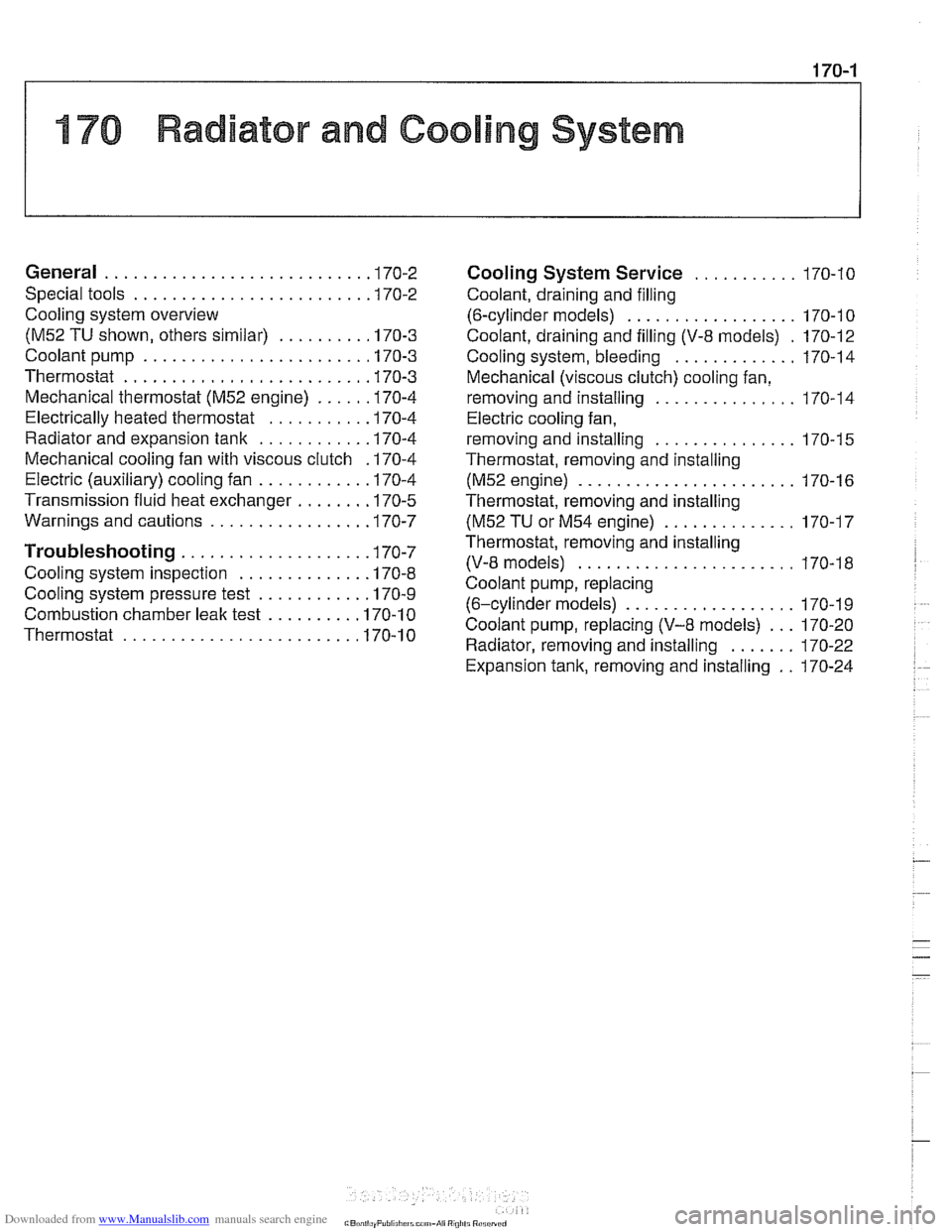
176 Radiator and Cooling System
General ........................... .I7 0.2
Special tools
........................ .I7 0.2
Cooling system overview
(M52 TU shown. others similar) ......... .I7 0.3
Coolant pump
....................... .I7 0.3
Thermostat
......................... .I7 0.3
Mechanical thermostat (M52 engine)
..... .I7 0.4
Electrically heated thermostat
.......... .I7 0.4
Radiator and expansion tank
........... .I7 0.4
Mechanical cooling fan with viscous clutch
.I7 0.4
Electric (auxiliary) cooling fan ........... .I7 0.4
Transmission fluid heat exchanger
....... .I7 0.5
Warnings and cautions
................ .I7 0.7
Troubleshooting ................... .I7 0.7
Cooling system inspection
............. .I7 0.8
Cooling system pressure test
........... .I7 0.9
Combustion chamber leak test
......... .I7 0.10
Thermostat
........................ .I7 0.1 0
Cooling System Service ........... 170-10
Coolant. draining and filling
(6-cylinder models)
.................. 170-1 0
Coolant. draining and filling (V-8 models)
. 170-12
Cooling system. bleeding
............. 170-14
Mechanical (viscous clutch) cooling fan.
removing and installing
............... 170-14
Electric cooling fan.
removing and installing
............... 170-15
Thermostat. removing and installing
(M52engine) ....................... 170-16
Thermostat. removing and installing
(M52 TU or M54 engine) .............. 170-17
Thermostat. removing and installing (V-8 models)
....................... 170-1 8
Coolant pump. replacing (6-cylinder models)
.................. 170-1 9
Coolant pump. replacing (V-8 models) ... 170-20
Radiator. removing and installing
....... 170-22
Expansion tank. removing and
installing . . 170-24
Page 634 of 1002
Downloaded from www.Manualslib.com manuals search engine
300-1 4
I Susoension. Steerina and Brakes - General
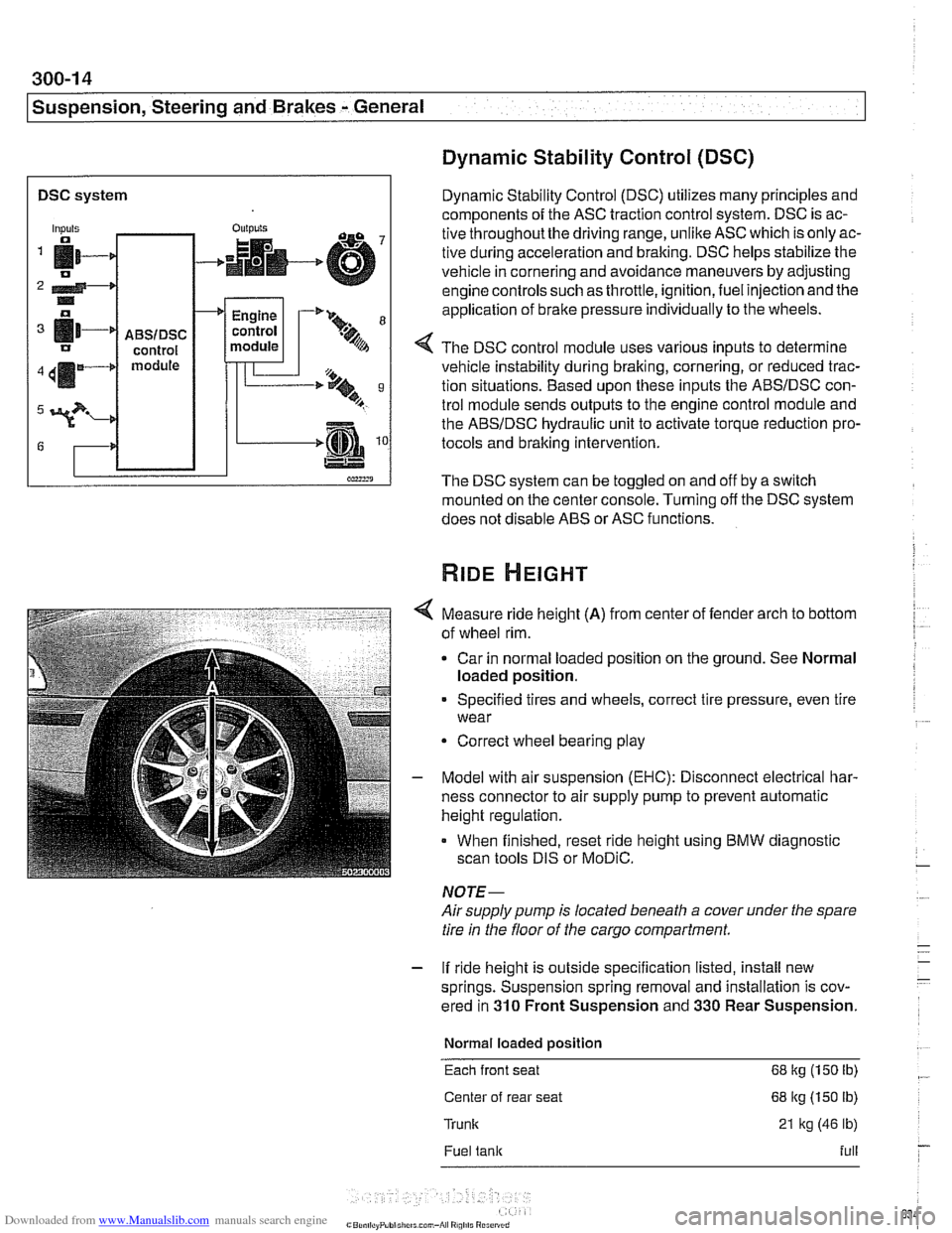
DSC system I
Dynamic Stability Control (DSC)
Dynamic Stability Control (DSC) utilizes many principles and
components of the ASC traction control system. DSC is ac-
tive throughoutthe driving range, unlike ASC which is only ac-
tive during acceleration and braking. DSC helps stabilize the
vehicle in cornering and avoidance maneuvers by adjusting
engine controls such as throttle, ignition, fuel injection and the
application of
brake pressure individually to the wheels.
Inputs
fi- 0
2 4-* .. o
[11-' IJ
411m4
3?-
G
4 The DSC control module uses various inputs to determine
vehicle instability during braking, cornering, or reduced trac-
tion situations. Based upon these inputs the ABSIDSC con-
trol module sends outputs to the engine control module and
the ABSIDSC hydraulic unit to activate torque reduction pro-
tocols and braking intervention.
-
ABSIDSC control module
OUI~YIS
4
The DSC system can be toggled on and off by a switch
mounted on the center console. Turning off the DSC system
does not disable ABS or ASC functions.
+
Measure ride height (A) from center of fender arch to bottom
of wheel rim.
Car in normal loaded position on the ground. See Normal
loaded position.
Engine
control
module
Specified tires and wheels, correct tire pressure, even tire
wear
-'* 9-
.%A
Correct wheel bearing play
T'== ..t, 9 B
-.m
Model with air suspension (EHC): Disconnect electrical har-
ness connector to air supply pump to prevent automatic
height regulation.
When finished, reset ride height using BMW diagnostic
scan tools DIS or
MoDiC.
NOTE-
Airsupply pump is located beneath a cover under the spare
tire in the floor of the cargo compartment.
- If ride height is outside specification listed, install new
springs. Suspension spring removal and installation is cov-
ered in
310 Front Suspension and 330 Rear Suspension.
Normal loaded position
Each front seat 68 kg (150 Ib)
Center of rear seat 68 kg (150 lb)
Trunk 21 kg (46 lb)
Fuel tank full
Page 665 of 1002
Downloaded from www.Manualslib.com manuals search engine
320-7
Steering and Wheel ~liqnmentl
STEERING WHEEL
Steering wheel, removal and installation
WARNING -
The BMWairbag system (Supplemental Restraint System or
SRS) is complex. Special precautions must be observed
when servicing. Serious injury may result if
SRS system serv-
ice is
attempted by persons unfamiliar with the BMW SRS
and its approved service procedures. BMW specifies that all
inspection andservice should be preformed by an authorized
BMW dealer.
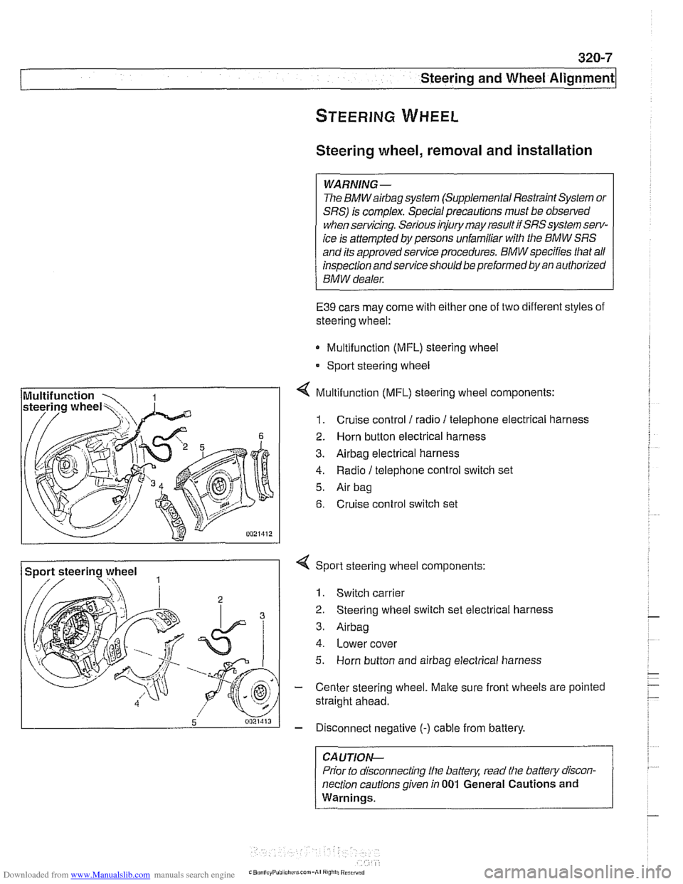
E39 cars may come with either one of two different styles of
steering wheel:
Multifunction (MFL) steering wheel
* Sport steering wheel
4 Multifunction (MFL) steering wheel components:
1. Cruise control 1 radio 1 telephone electrical harness
2. Horn button electrical harness
3. Airbag electrical harness
4. Radio / telephone control switch set
5. Air bag
6. Cruise control switch set
Sport steering wheel
3
5 0021413
4 Sport steering wheel components:
1. Switch carrier
2 Steering wheel switch set electrical harness
3. Airbag
4. Lower cover
5. Horn button and airbag electrical harness
- Center steering wheel. Make sure front wheels are pointed
straight ahead.
- Disconnect negative (-) cable from battery.
CA UTIOP&
Prior to disconnecting the battern read the battew discon-
nection cautions given in
001 General Cautions and
Warnings.
-
Page 705 of 1002
Downloaded from www.Manualslib.com manuals search engine
--
C. -- -- - -- Rear ~us~ensionl
Depending on year and model applications, the Sport Wagon
rear suspension may be equipped with:
Conventional shock absorbers and coil springs
Electronic height control (EHC) system which incorporates
air springs
NOTE-
. Suspension and EHC troubleshooting is covered in 300
Suspension, Steering and Brakes-General.
EHC system repairs, other than air spring replacement,
are covered in Electronic height control
(EHC) compo-
nent replacement.
Replace shock absorbers and springs in pairs only.
Rear shock absorber, removing and
installing
- Raise car and remove rear wheels,
WARNING-
Male sure that the car is firmly supported on jack stands de-
signed for the purpose. Place jack stands underneath struc-
tural chassis points. Do not place
jack stands under
suspension parts.
CAUTION-
If working on a vehicle with compressedairshock absorbers,
disable air supply pump by disconnecting electrical plug be-
fore performing any repairs. Pump is located beneath a cover
under the spare tire in the floor of the cargo compartment.
- Support swing arm from below
CAUTIOG
The shock absorber prevents the drive axle and wlieel bear-
ing carrier from dropping too far. Supporting the wheel bear-
ing carrier before disconnecting the shock absorber
mounting fasteners prevents damage to the
brake hose,
parking
brake cable and drive axle CVjoints.
- Working in cargo compartment, remove carpet. Remove tri-
angular upper shock mount covers located beside spare tire
well.
- If applicable: Detach air supply line from shock absorber.
Plug ports and lines to keep out dirt.
Page 799 of 1002
Downloaded from www.Manualslib.com manuals search engine
400-5
Body-General
Tailgate
The E39 Sporl Wagon tailgate is large with a low sill for easy
cargo loading. The tailgate opens to an angle of
88" mea-
sured from the rear roof pillar (D-pillar) and to a height of
2029
mm (79.8 in) measured from the ground to the upper edge of
the raised tailgate.
The rear window is bonded to a load bearing frame and can
be opened separately from the main tailgate. Tailgatesupport
gas springs are recessed into cavities in the roof.
Tailgate lock system
A mechanical tailgate lock cylinder is not used; the tailgate is
opened by the unlock pad above the license plate, the remote
tailgate switch located in the drivers kick panel, or via
FZV
(Iteyless entry) control.
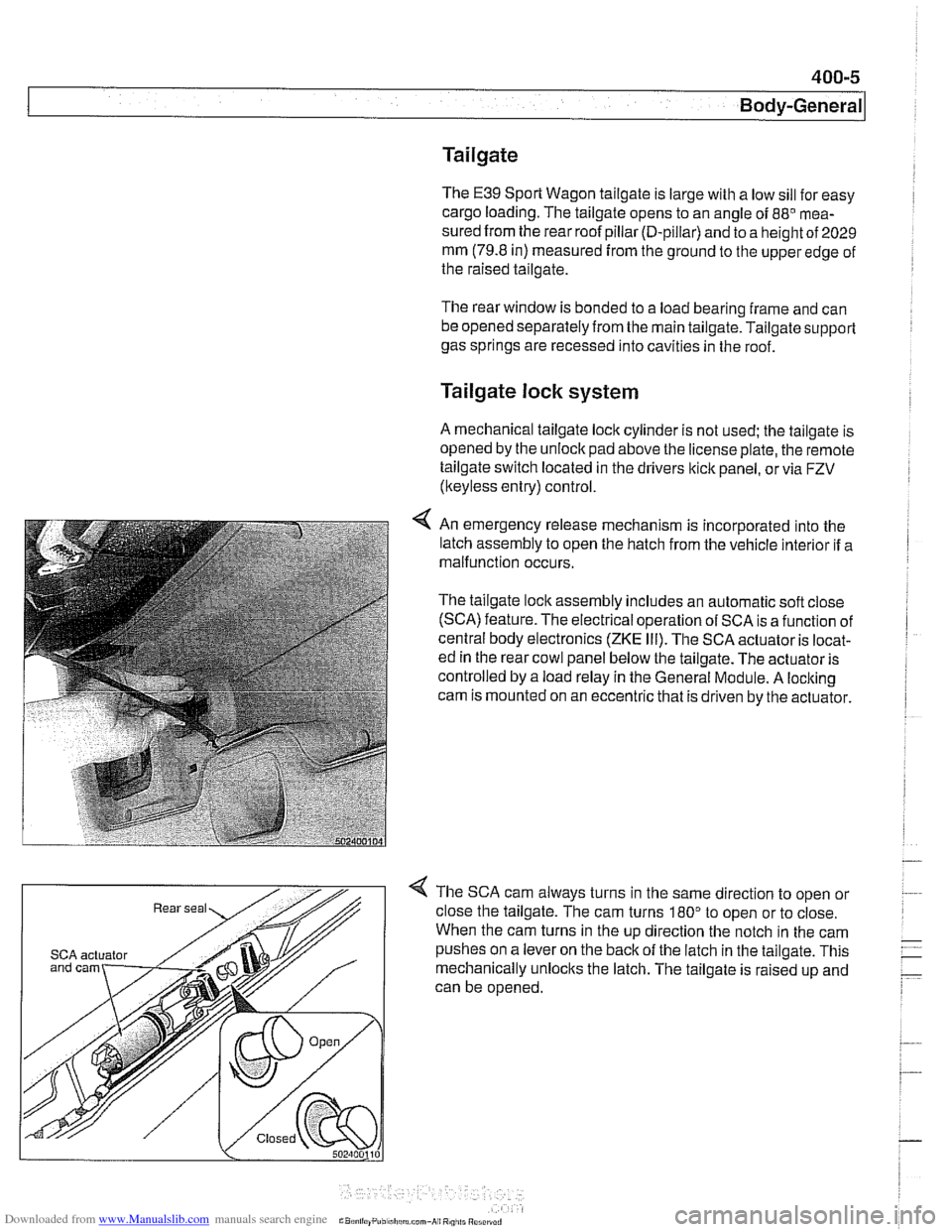
4 An emergency release mechanism is incorporated into the
latch assembly to open the hatch from the vehicle interior if a
malfunction occurs.
The tailgate lock assembly includes an automatic soft close
(SCA) feature. The electrical operation of SCA is a function of
central body electronics
(ZKE Ill). The SCA actuator is locat-
ed in the rear cowl panel below the tailgate. The actuator is
controlled by a load relay in the General Module. A locking
cam is mounted on an eccentric that is driven by the actuator.
4 The SCA cam always turns in the same direction to open or
close the tailgate. The cam turns
180" to open or to close.
When the cam turns in the up direction the notch in the cam
SCA actuator pushes on a lever on the back of the latch in the tailgate. This
mechanically unlocks the latch. The tailgate is raised up and
can be opened.
Page 803 of 1002
Downloaded from www.Manualslib.com manuals search engine
400-9
Body-General
Battery safety terminal
(BST)
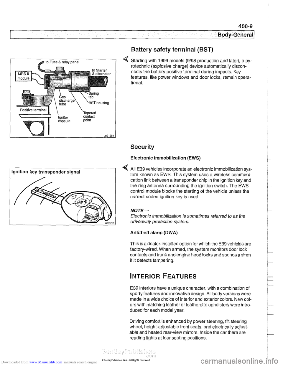
4 Starting with 1999 models (9198 production and later), a py-
rotechnic (explosive charge) device automatically discon-
nects the battery positive terminal during impacts. Key
features,
like power windows and door locks, remain opera-
tional.
Security
Electronic immobilization (EWS)
Ignition key transponder signal All
E39 vehicles incorporate an electronic immobilization sys-
tem known as EWS. This svstem uses a wireless comrnuni-
cation link between a transponder chip in the ignition key and
the ring antenna surrounding the ignition switch. The EWS
control module blocks the starting of the vehicle unless the
correct coded ignition key is used.
NOTE-
Electronic immobilization is sometimes referred to as the
driveaway protection system.
Antitheft alarm (DWA)
This is adealer-installed option for which the E39 vehicles are
factory-wired. When armed, the system monitors door
loci(
contacts and trunk and engine hood locks and sounds a siren
if it detects tampering.
E39 interiors have a unique character, with a combination
of
sporty features and innovativedesign. All body versions were
made in a wide choice of interior and exterior colors. New col-
ors with matching leather or leatherette upholstery were intro-
duced for each model year.
Driving
comfort is enhanced by power steering, tilt steering
wheel, height-adjustable front seats, and electrically adjust-
able and heated rear-view mirrors. Inside the car there are
reading lights at four seating positions.