Obd BMW 528i 1998 E39 Owner's Guide
[x] Cancel search | Manufacturer: BMW, Model Year: 1998, Model line: 528i, Model: BMW 528i 1998 E39Pages: 1002
Page 473 of 1002
Downloaded from www.Manualslib.com manuals search engine
Fuel Tank and Fuel Pump
Fuel pump
The electric fuel pump is mounted in the fuel tank in tandem
with the right side fuel level sender. The fuel pump delivers
pressurized fuel to the fuel injection system.
A pressure regu-
lator maintains system pressure. The quantity of fuel supplied
exceeds demand, so excess fuel returns to the fuel tank via a
return line. See
130 Fuel Injection for more information.
NOTE-
Fuel pump removal procedures are given under Fuel level
sender (right side) and fuel pump, removing and install-
ing.
Fuel tank evaporative control system
Evaporative control, also referred to as running losses con-
trol, is designed to prevent fuel system evaporative losses
from venting into the atmosphere.
The components of this system allow control and monitoring
of evaporative losses by the on-board diagnostic
(OED II)
software incorporated into the engine control module (ECM).
NOTE-
1997 V-8 models (540i) with Bosch DME M5.2 are not
equipped with an
OBD I1 running losses monitoring system.
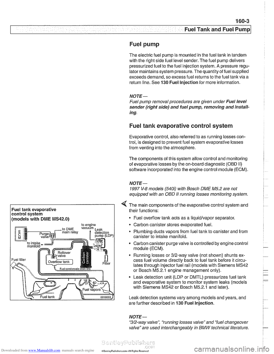
Fuel tank evaporative
control system
(models with
DME MS42.0)
4 The main components of the evaporative control system and
their functions:
Fuel overflow
tank acts as a liquidlvapor separator
Carbon canister stores evaporated fuel.
Plumbing ducts vapors from fuel tank to canister and from
canister to intake
manifold.
- Carbon canister purge valve is controlled by enginecontrol
module (ECM).
Running losses or 312-way valve (not shown) shunts ex-
cess fuel volume directly
back to fuel tank before it circu-
lates through injector fuel rail (models with Siemens MS42
or Bosch M5.2.1 engine management only).
Leak detection unit (LDP or DMTL) pressurizes fuel
tank
and evaporative system to monitor system leaks (models
with Siemens MS42 or Bosch M5.2.1 and later).
Leak detection systems vary among models and years, and
are further described in
130 Fuel Injection.
NOTE -
"3/2-way valve", 'tunning losses valve" and "fuel changeover
valve" are used interchangeably
in BMW technical literature.
Page 474 of 1002
Downloaded from www.Manualslib.com manuals search engine
Fuel Tank and Fuel Pump
Evaporative system troubleshooting
- Start by accessing diagnostic trouble codes (DTCs) using a
BMW or BMW compatible aftermarket scan tool.
For purposes of OBD
II emissions compliance, the DME
system sets a diagnostic trouble code (DTC) when it de-
tects a leak that is equal or larger than minimum
lealc
sensed by system.
Malfunction Indicator Light (MIL) is illuminated upon sec-
ond recurrence of fault. See OBD On-Board Diagnostics.
- When leak testing, observe following conditions to obtain
plausible results:
Fuel tank
'1, to 'I., full.
0 Vehicle parked for at least 2 hours to allow fuel to reach
room temperature.
Ideal fuel temperature is 10"- 20°C
(50"
- 68" F).
Do not refuel immediately before
lealc test.
- If a leak is detected, check the following areas:
* Fuel filter cap (leaking or off).
Fuel tank ventilation lines leaking at fuel
tank or activated
carbon canister.
i
Tank ventilation valve leaking (in engine compartment).
Fuel level
sensorlfuel pump cap leaking.
Evaporative system component replacement is covered later
in
th~s group in Fuel Tank and Fuel Lines.
Page 495 of 1002
Downloaded from www.Manualslib.com manuals search engine
160-25
Fuel Tank and Fuel pump1
The 312-way valve is also activated briefly if an engine misfire
is detected. This provides full fuel flow through the fuel rail to
determine if the misfire was caused by a lean fuel condition.
The valve is monitored by the ECM forfaults.
- Using BMW or compatible scan tool, read out fault memory.
See
OBD On-Board Diagnostics.
- Turn off ignition.
- Raise car and support safely.
CA UTIOW
Male sure the car is stable and well suppodedat all times.
Use a professional automotive lift
orjack stands designed for
the purpose.
A floor jack is not adequate support.
- Worlting under car beneath driver's seat, remove protective
panel from fuel filter and 312-way valve.
- Clamp off fuel lines at 312-way valve.
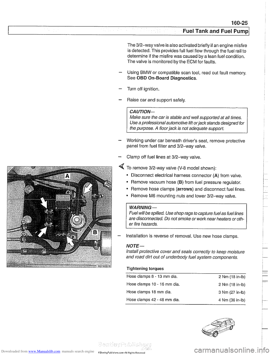
4 To remove 312-way valve (V-8 model shown):
Disconnect electrical harness connector
(A) from valve.
Remove vacuum hose
(B) from fuel pressure regulator.
* Remove hose clamps (arrows) and disconnect fuel lines.
Remove
M6 mounting nuts and lower 312-way valve.
WARNING-
Fuel will be spilled. Use shop rags to capture fuelas fuellines
are disconnected. Do not
smoke or work near heaters or oth-
er fire hazards.
- Installation is reverse of removal. Use new hose clamps
NOTE-
Install protective cover and seals correctly to keep moisture
and road dirt out of underbody fuel system components.
Tightening torques Hose clamps
8 - 13 mm dia.
2 Nm (18 in-lb)
Hose clamps
10 - 16 mm dia.
2 Nm (18 in-lb)
Hose clamps
18 mm dia. 3 Nm (27 in-lb)
Hose clamps 42
- 48 mm dia. 4 Nm 136 in-ib)
Page 506 of 1002
Downloaded from www.Manualslib.com manuals search engine
170-1 0
I Radiator and Cooling System
Combustion chamber leak test
- If you suspect that combustion chamber pressure is leaking
into the cooling system past the cylinder head gasket, use an
exhaust gas analyzer to test the vapors rising from the cool-
ant at the expansion tank.
CAUTIO&
Use an extension tube above the reservoir neclc to main-
tain distance between the top of the coolant and the gas
analyzer
nozzle. The gas analyzer is easily damaged if it is
allowed to inhale liquid coolant.
* While running engine to checlc for causes of overheat-
ing, observe coolant temperature carefully in order to
avoid engine damage.
Thermostat
If the engine overheats or runs too cool and no other cooling
system tests indicate trouble, the thermostat may be faulty.
In
V-8 models and 6-cvlinder models nroduced afler 911 998
(M52TU or M54 eng'ne), rheelecrricaily heated rhermostal IS
mon tored by [he OBD II diagnostlc software The fault may ic
in the DME software or hardware, or it may lie in the wiring to
the thermostat. See
OED On-Board Diagnostics.
Coolant, draining and filling
(6-cylinder models)
WARNING -
Allow the cooling system to cool before opening or draining
the cooling system.
- Raise front of car and support safely.
WARNING -
Make sure the car is stable and well supported at all times.
Use a professional automotive lift
orjack stands designed for
the purpose. A floor jack is not adequate support.
- Remove splash shield from under engine.
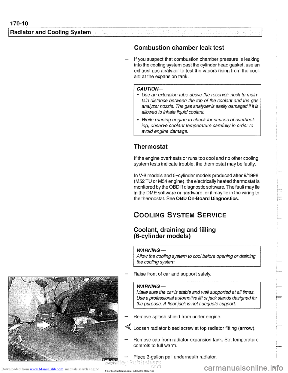
4 Loosen radiator bleed screw at top radiator fitting (arrow).
- Remove cap from radiator expansion tank. Set temperature
controls to
full warm.
gallon pail underneath radiator.
Page 771 of 1002
Downloaded from www.Manualslib.com manuals search engine
Brakes
Brakes, bleeding
The procedure below requires a BMW Service Tester (DIS-
pluslGTl/MoDiC).
- Determine type of traction control (ASC, DSC with precharge
pump, DSC without precharge pump). Be sure to use correct
specification brake fluid, according to application table below.
Brake fluid applications
ABS I ASC and ABS / DSC models DOT 4 brake fluid
with precharge pump (to 911998)
ABS I DSC models without precharge DOT 4 low viscosity
pump (911998 and later) brake
fluid
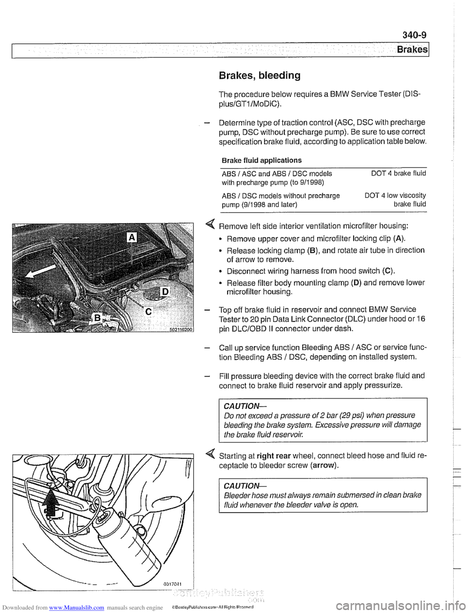
< Remove left side interior ventilation microfilter housing:
Remove upper cover and microfilter loclting clip
(A).
Release locking clamp (B), and rotate air tube in direction
of arrow to remove.
Disconnect wiring harness from hood switch
(C).
Release filter body mounting clamp (D) and remove lower
microfilter housing.
- Top off bralte fluid in reservoir and connect BMW Service
Tester to
20 pin Data Link Connector (DLC) under hood or 16
pin
DLCIOBD I1 connector under dash.
- Call up service function Bleeding ABS / ASC or service func-
tion Bleeding ABS
/ DSC, depending on installed system.
- Fill pressure bleeding device with the correct brake fluid and
connect to brake fluid reservoir and apply pressurize.
Do not exceed a pressure of
2 bar (29 psi) when pressure
bleeding the
brake system. Excessive pressure will damage
4 Starting at right rear wheel, connect bleed hose and fluid re-
ceptacle to bleeder screw (arrow).
CA UTlON-
Bleeder hose must always remain submersed in clean brake
fluid whenever the bleeder valve is open.
Page 783 of 1002
Downloaded from www.Manualslib.com manuals search engine
1 Brakes
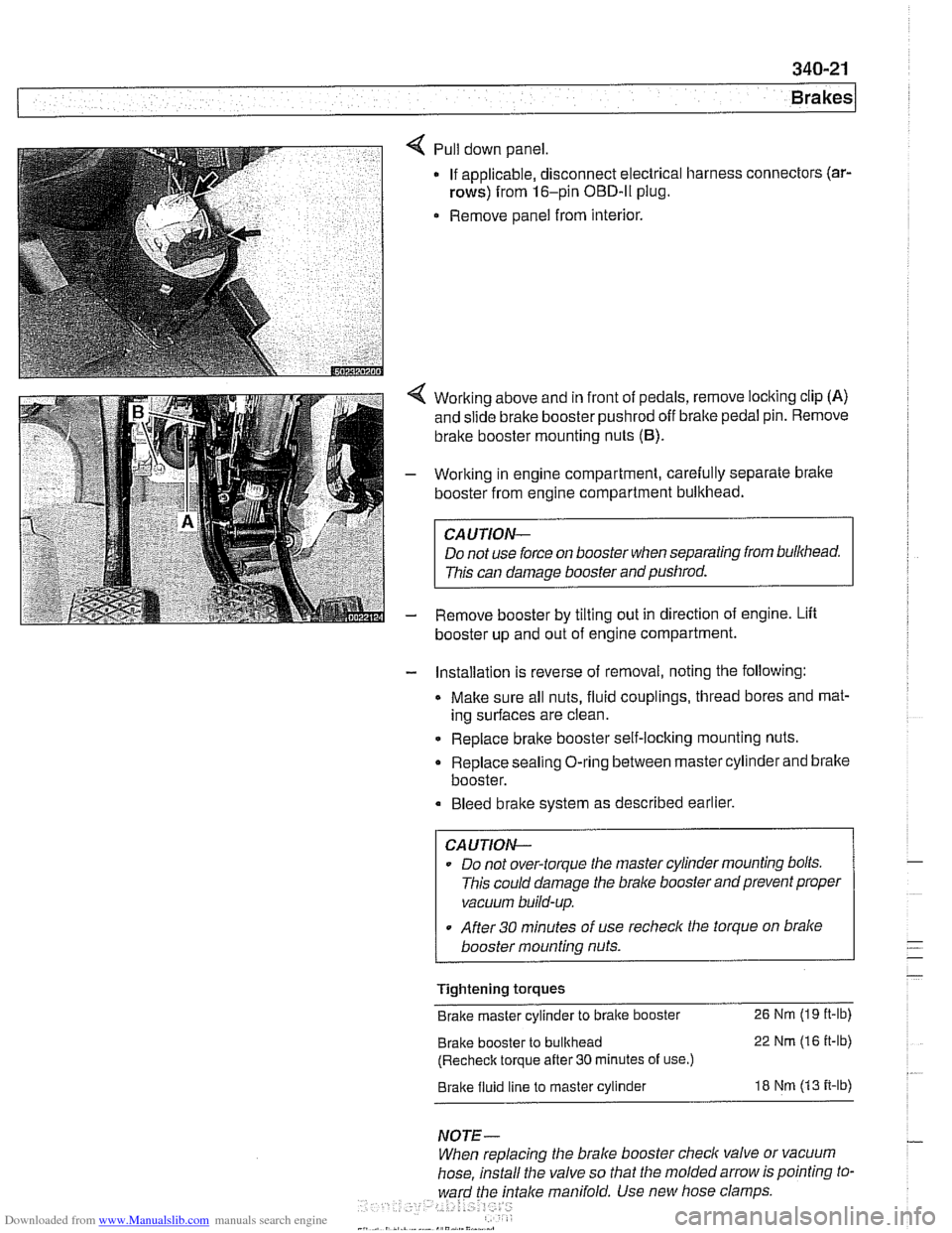
Pull down panel
If applicable, disconnect electrical harness
rows) from 16-pin OBD-ll plug.
Remove panel from interior. connectors
(ar-
Working
above and in front of pedals, remove locking clip (A)
and slide brake booster pushrod off bralte pedal pin. Remove
brake booster mounting nuts
(6).
Working in engine compartment, carefully separate bralte
booster from engine compartment bulkhead.
CAUTION-
Do not use force on booster when separating from bulkhead.
This can damage booster and pushrod.
Remove booster by tilting out in direction of engine. Lift
booster up and out of engine compartment.
- Installation is reverse of removal, noting the following:
Make sure all nuts, fluid couplings, thread bores and mat-
ing surfaces are clean.
Replace bralte booster self-locking mounting nuts.
Replace sealing O-ring between master cylinder and bralte
booster.
Bleed bralte system as described earlier.
CAUTION--
Do not over-torque tlie master cylinder mounting bolts.
This could damage the
bralce booster and prevent proper
vacuum build-up.
After
30 minutes of use recheclc the torque on bralce
booster mounting nuts.
Tightening torques
Brake master cylinder to brake booster
26 Nm (19 it-lb)
Brake booster to bulkhead 22 Nm (16 it-lb)
(Recheck torque after
30 minutes of use.)
Brake fluid line to master cylinder 18 Nm (13 it-lb)
NOTE-
When replacing the brake booster check valve or vacuum
hose, install the valve so that the molded arrow is pointing to-
ward the
fntalce manifold. Use new hose clamps
Page 961 of 1002
Downloaded from www.Manualslib.com manuals search engine
OBD On-Board Diagnostics
I I
General ........................... OBD-1 Diaqnostic Trouble Codes (DTCs) . . OBD-9
On-Board Diagnostics (OBD I!) ..... OBD-I
Malfunction Indicator Light (MIL)
........ OBD-2
Scan tools and scan tool display.
........ OBD-3
Diagnostic monitors
.................. OED-4
Drive cycle
......................... OED-6
Readiness codes
.................... OBD-6
Diagnostic trouble codes
(DTCs) ........ OBD-7
-
Automatic transmission diagnostic
trouble codes
....................... OBD-9
Engine diagnostic trouble
codes: M52 engine.
................. OED-13
Engine diagnostic trouble
codes: M54 engine.
................. OBD-17
Engine diagnostic trouble
codes: M62 engine.
................. OBD-24
This chapter outlines the fundamentals and equipment
requirements of On-Board Diagnostics
I1 (OBD 11) standards
as they apply to BMW vehicles. Also covered here is a listing
of BMW and OBD
I1 diagnostic trouble codes (DTCs).
ON-BOARD DIAGNOSTICS (QBD !I)
OBD II standards were developed by the SAE (Society of
Automotive Engineers) and CARB (California Air Resources
Board).
OED I1 is the second generation of on-board self-
diagnostic equipment requirements. These standards were
originally mandated for California vehicles. Since
1996 they
have been applied
toall passengervehicles sold in the United
States.
On-board diagnostic capabilities are incorporated into the
hardware and soflwareof the enginecontrol module
(ECM) to
monitor virtually every component that can affect vehicle
emissions. The
OED I1 system works to ensure that
emissions remain as clean as possible over the life of the
vehicle.
Each emission-influencing component is checked by a
diagnostic routine (called a monitor) to verify that it is
functioning properly.
If a problem or malfunction is detected,
the
diagnostic executive built into the OBD I1 system
illuminates a malfunction indicator light (MIL) on the
instrument panel.
The OBD
I1 system also stores diagnostic trouble codes
(DTCs) about the detected malfunction in the ECM so that a
repair technician can accurately find and fix the problem.
Page 963 of 1002
Downloaded from www.Manualslib.com manuals search engine
OBD-3
On-Board
~iactnosticsl
Additional MIL information:
A fault code is stored within the ECM upon the first
occurrence of a fault in the system being checlted.
Two complete consecutive drive cycles with the iault
present illuminate the MIL. The exception to the two-fault
requirement is a catalyst-damaging fault, which illuminates
the MIL immediately.
If the second drive cycle was not complete and the fault
was not checked, the ECM counts the third drive cycle as
the next consecutive drive cycle. The MIL illuminates
if the
system is checked and the fault is still present.
Once the MIL is illuminated, it remains illuminated until the
vehicle completes three consecutive drive cycles without
detecting a fault.
0 An existing fault code is cleared from memory
automatically when the vehicle completes
40 consecutive
drive cycles without the fault being detected.
In order to automatically clear a catalyst-damaging fault from
memory, the condition underwhich the fault occurred must be
evaluated for 80 consecutive drive cycles without the fault
reoccurring.
A generic scan tool connected to the BMW data link
connector (DLC) or OBD
I1 plug can display diagnostic trouble
codes (DTCs), along with the conditions associated with the
illumination of the MIL. Using a more advanced or
BMW-
dedicated scan tool, additional proprietary information is
normally available.
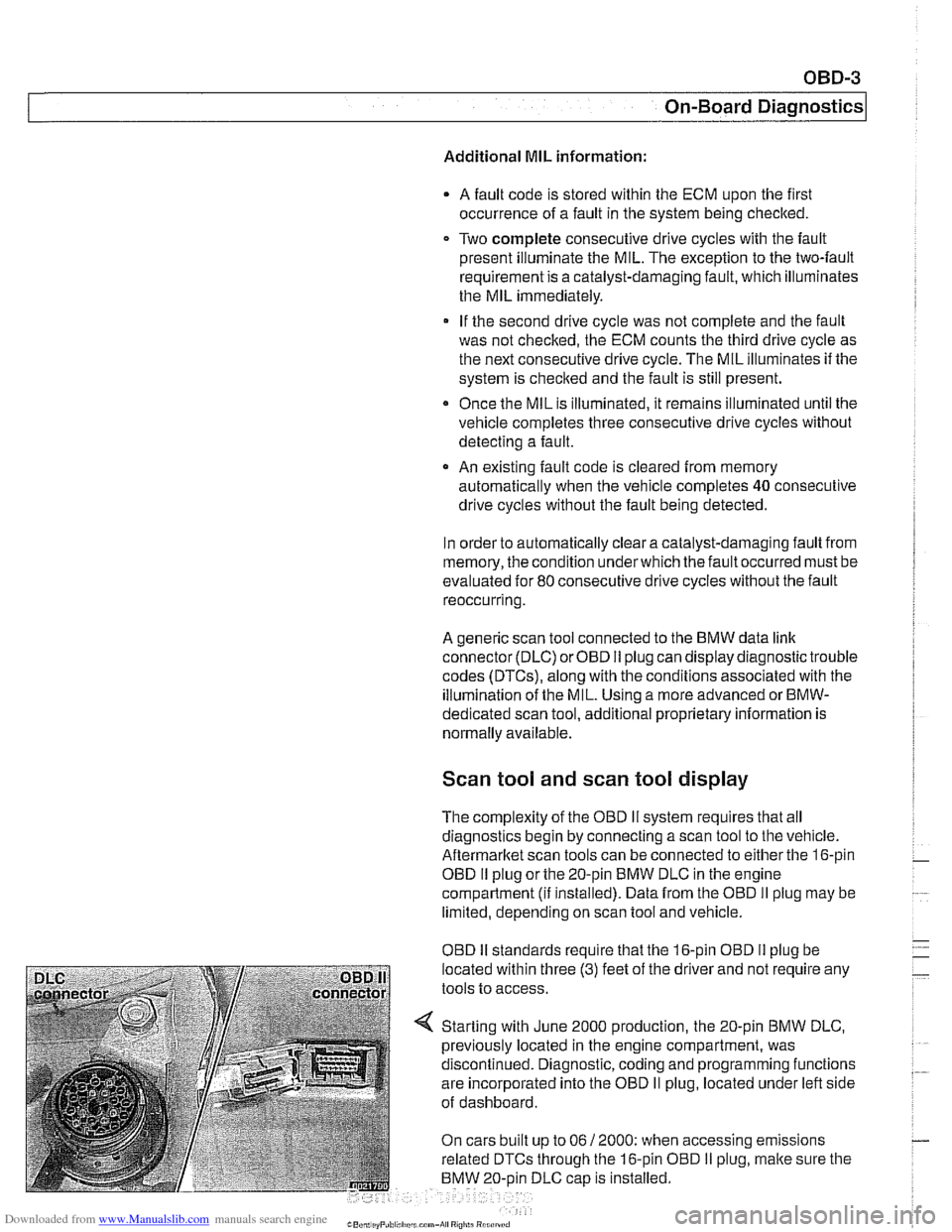
Scan tool and scan tool display
The complexity of the OBD I1 system requires that all
diagnostics begin by connecting a scan tool to the vehicle.
Aftermarltet scan tools can be connected to either the 16-pin
OBD
I1 plug or the 20-pin BMW DLC in the engine
compartment
(ii installed). Data from the OBD II plug may be
limited, depending on scan tool and vehicle.
OBD
I1 standards reouire that the 16-oin OBD I1 oluo be
located within three
(3) feet of the driier and not're&ire any
tools to access.
Starting with June 2000 production, the 20-pin BMW DLC,
previously located in the engine compartment, was
discontinued. Diagnostic, coding and programming functions
are incorporated into the OBD
II plug, located under left side
of dashboard.
On cars built up to 06
/ 2000: when accessing emissions
related DTCs through the 16-pin OBD
I1 plug, malte sure the
BMW 20-oin DLC
caD is installed.
Page 964 of 1002
Downloaded from www.Manualslib.com manuals search engine
- -
On-Board Diagnostics
Professional diagnostic scan tools available atthe time of this
printing include the BMW factory tools
(DISplus, GTI,
MoDiC) and a small number of aftermarket BMW-specific
tools. See
020 Maintenance.
In addition to the professional line of scan tools, inexpensive
generic OBD
II scan tool software programs and handheld
units are readily available. Though limited, they are
nonetheless powerful diagnostic tools. These tools read live
data streams and freeze frame data as well as a host of other
valuable diagnostic data.
Diagnostic monitors
Diagnostic monitors run tests and checks on specific
emission control systems, components, and functions.
A complete drive cycle is requiredforthe tests to bevalid. See
Drive cycle in this repair group. The diagnostic monitor
signals the
ECM of the loss or impairment of the signal or
component and determines if a signal or sensor is faulty
based on
3 conditions:
* Signal or component shorted to ground
Signal or component shorted to
B+
Signal or component missing (open circuit)
The OBD
II system monitors all emission control systems that
are installed. Emission control systems vary by vehicle model
and year. For example, a vehicle may not be equipped with
secondary air injection, so no secondary air readiness code
would be present.
OBD
II software monitors the following:
Oxygen sensors
Catalysts
Engine misfire
- Fuel tank evaporative control system
Secondary air injection Fuel system
Oxygen sensor monitoring. When driving conditions allow,
response rate and switching time of each oxygen sensor is
monitored. The oxygen sensor heater function is also
monitored. The OBD
II system differentiates between
precataylst and post-catalyst oxygen sensors and reads each
one individually. In order
forthe oxygen sensor to be
effectively monitored, the system must be in closed loop
operation.
Page 966 of 1002
Downloaded from www.Manualslib.com manuals search engine
OBD-6
On-Board Diagnostics
Fuel system monitoring. This monitor looks at the fuel
delivery needed (long
/short term fuel trim) for proper engine
operation based on programmed data. If too much or not
enough fuel is delivered over a predetermined time, a DTC is
set and the MIL illuminates.
Fuel trim refers to adiustments to base fuel schedule.
Lono- ., term fuel trim refers to gradual adjustments to the fuel
calibration adjustment as compared to short term fuel trim.
Long term fuel trim adjustments compensate for gradual
changes that occur over time.
Fuel system monitoring monitors the calculated injection time
(ti) in relation to enginespeed, load and precatalyticconverter
oxygen
sensor(s) signals.
Using this data, the system optimizes fuel delivery for all
engine operating conditions.
Evaporative system monitoring. This monitor checks the
the fuel storage system and related fuel lines for leaks. It can
detect very small leaks anywhere in the system.
A leak detection unit (LDP or DMTL) is used to pressurize the
evaporative control system on a continuous basis (as the
drive cycle allows) and to
check system integrity.
Drive cycle
The OED II drive cycle is an important concept in
understanding OBD
II requirements. The purpose of the drive
cycle is to run ail of the emission-related on-board diagnostics
over a broad range of driving conditions.
A drive cycle is considered complete when all of the
diagnostic monitors have run their tests without interruption.
~ora drive cycle to be initiated, the vehicle must be started
cold and brought up to
1 60°F and at least 40°F above its
original starting temperature.
Readiness codes
Inspection/maintenance (I/M) readiness codes are mandated
as part of OBD
II. The readiness code is stored aftercomplete
diagnostic monitoring of specified components and systems
is carried out. The readiness code function was designed to
prevent manipulating an
I/M emission test procedure by
clearing faults codes or disconnecting the ECM or battery.