Signal BMW 528i 1998 E39 Repair Manual
[x] Cancel search | Manufacturer: BMW, Model Year: 1998, Model line: 528i, Model: BMW 528i 1998 E39Pages: 1002
Page 464 of 1002
Downloaded from www.Manualslib.com manuals search engine
130-74
I Fuel Injection
Evaporative system pressure leak
diagnosis, overview
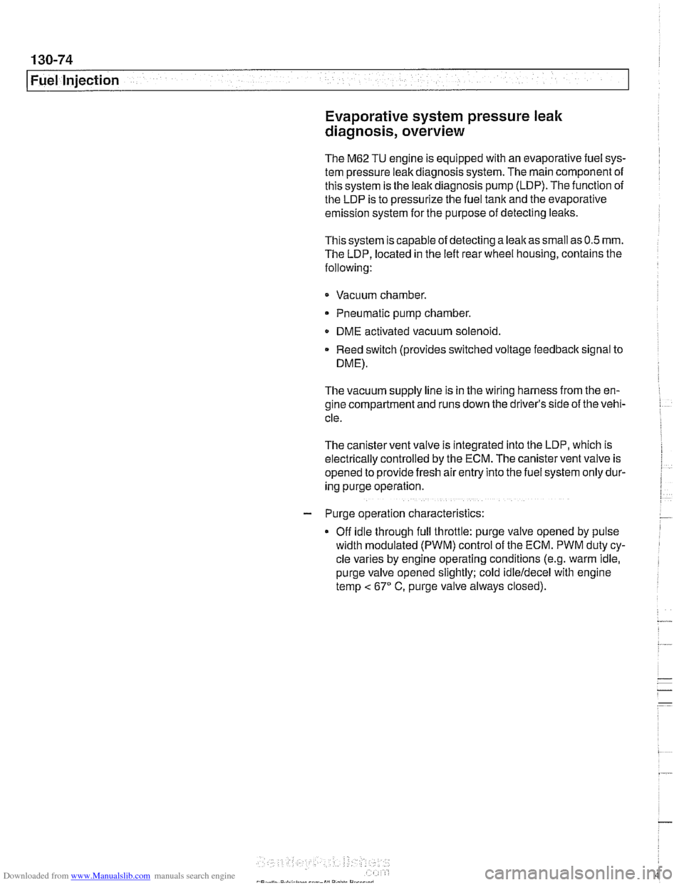
The M62 TU engine is equipped wlth an evaporative fuel sys-
tem pressure leak diagnosis system. The main component of
this system is the leakdiagnosis pump (LDP). The function of
the LDP is to pressurize the fuel tank and the evaporative
emission system for the purpose of detecting leaks.
This system iscapable of detecting a
lealcas small as0.5 mm.
The LDP, located in the left rear wheel housing, contains the
following:
Vacuum chamber. Pneumatic pump chamber
DME activated vacuum solenoid
Reed switch (provides switched voltage
feedback signal to
DME).
The vacuum supply line is in the wiring harness from the en-
gine compartment and runs down the driver's side of the vehi-
cle.
The canister vent valve is
~ntegrated into the LDP, which IS
electrically controlled by the ECM. The canister vent valve is
opened to provide fresh air entry into the fuel system only dur-
ing purge operation.
- Purge operation characteristics:
Off idle through full throttle: purge valve opened by pulse
width modulated (PWM) control of the ECM. PWM duty cy-
cle varies by engine operating conditions
(e.g. warm idle,
purge valve opened slightly; cold
idleldecel with engine
temp
< 67" C. purge valve always closed).
Page 466 of 1002
Downloaded from www.Manualslib.com manuals search engine
130-76
Fuel Injection
Bosch
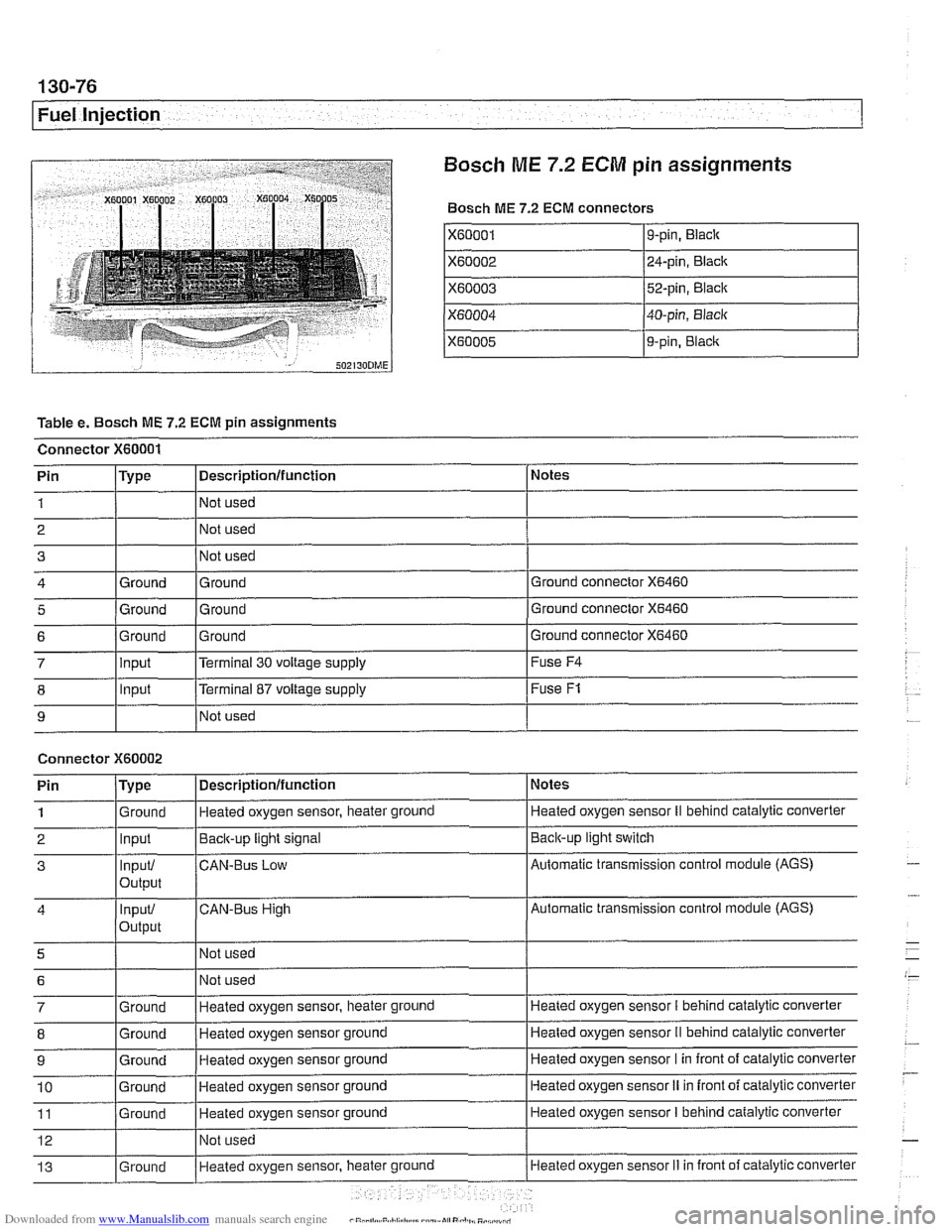
ME 7.2 ECM pin assignments
Bosch ME 7.2 ECM connectors
X60001
X60002
X60003
X60004
X60005
Table e. Bosch ME 7.2 ECM pin assignments
Connector
X60001
I I I
8 1 lnput [Terminal 87 voltage supply I Fuse F1
9-pin, Black
24-pin, Black
52-pin, Black
40-pin, Black
9-pin,
Blaclc
I I I
9 I NO^ used I
Notes
Ground connector
X6460
Ground connector X6460
Pin 1
2 3
4
5
Connector X60002
Ground connector X6460 6
Pin
/Type I Descriptionlfunction 1 Notes
Type
Ground
Ground
7 llnput l~errninai 30 voltage supply I Fuse F4
Descriptionlfunction
Not used
Not used
Not used
Ground Ground
Ground Ground
1
2
3
4
5
6
7
8
9
10
11
12
13
. . - Ground Input
Input/
output
input/
Output
Ground
Ground
Ground
Ground
Ground
Ground Heated oxygen sensor, heater ground
Back-up
light signal
CAN-BUS Low
CAN-Bus High
Not used Not used
Heated oxygen sensor, heater ground
Heated oxygen sensor ground
Heated oxygen sensor ground
Heated oxygen sensor ground
Heated oxygen sensor ground
Not used
Heated oxvaen sensor, heater
ground
Heated oxygen sensor II behind catalylic converter
Baclcup light switch
Automatic transmission control module (AGS)
Automatic transmission control module (AGS)
Heated oxygen sensor
I behind catalytic converter
Heated oxygen sensor
II behind catalytic converter
Heated oxygen sensor I in front of catalytic converter
Heated oxygen sensor
II in front of catalytic converter
Heated oxygen sensor
I behind catalytic converter
Heated oxygen sensor
Ii in front of catalytic converter
Page 467 of 1002
Downloaded from www.Manualslib.com manuals search engine
Fuel lnjection
I 1- I
4 /output l~em~erature signal. E-box fan I E-box fan
Connector
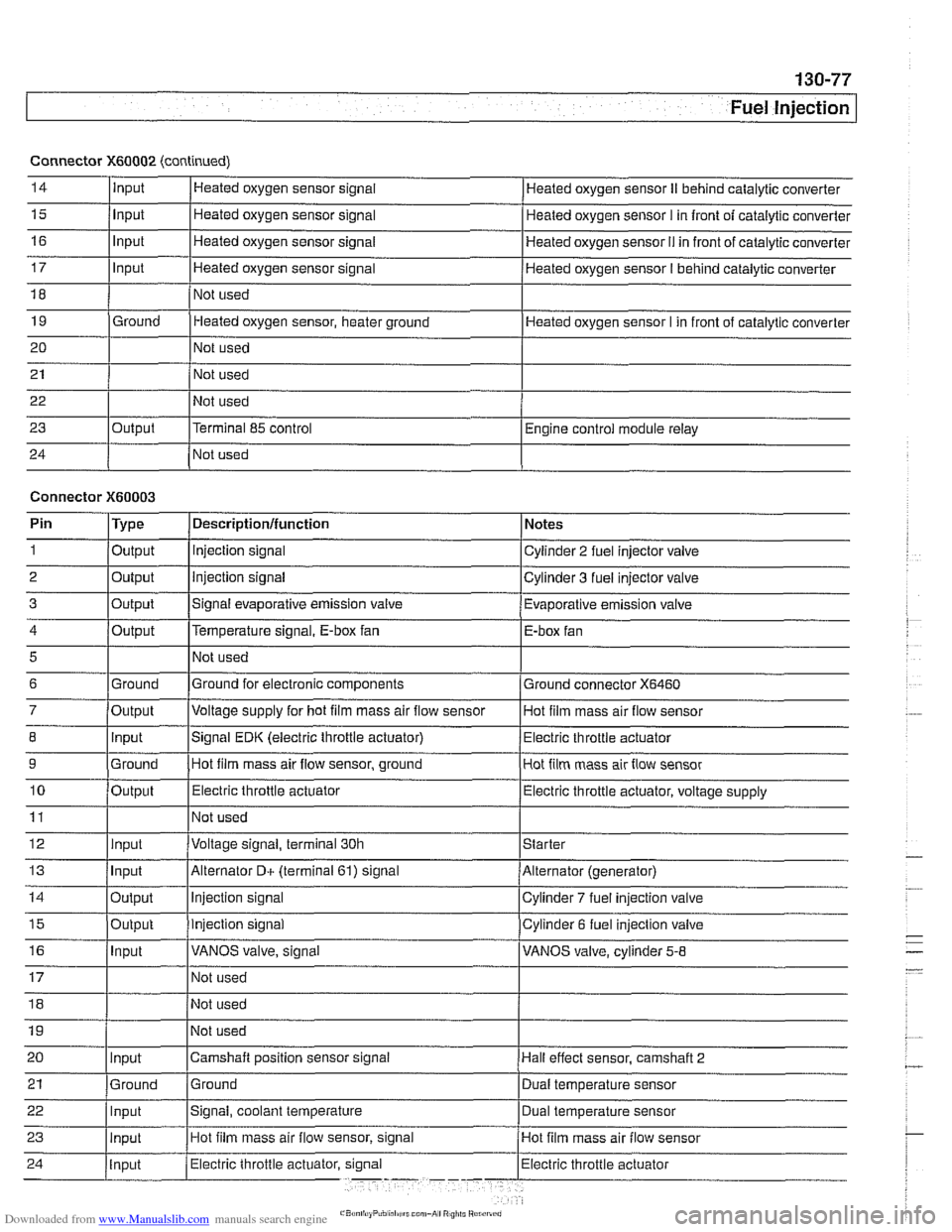
X60002 (continued)
14
15
16
17
18
19
20
21
22
23
24
5
6
7
8
9
10
11
12
13
14
15
16
Input
Input
Input
Input
Ground
Output Heated
oxygen sensor signal
Heated oxygen sensor signal
Heated oxygen sensor signal
Heated oxygen sensor signal
Not used
Heated oxygen sensor, heater ground
Not used
Not used
Not used
Terminal 85 control
Not used Heated oxygen sensor
II behind catalytic converter
Heated oxygen sensor
I in front of catalytic converter
Heated oxygen sensor
I1 in front of catalytic converter
Heated oxygen sensor
I behind catalytic converter
Heated oxygen sensor I in front of catalytic converter
Engine control module relay
Connector
X60003
Ground
Output Input
Ground
Output
Input
Input
Output
Output
Input
Pin 1
2
3
Not used
Ground for electronic components
Voltage supply for hot
film mass air flow sensor
Signal EDK (electric throttle actuator) Hot film mass air flow sensor, ground
Electric throttle actuator
Not used
Voltage signal, terminal 30h
Alternator
D+ (terminal 61) signal
Injection signal
Injection signal
VANOS valve, signal
Type
Output
Output
Output
Ground connector
X6460
Hot film mass air flow sensor
Electric throttle actuator
Hot film mass air flow sensor
Electric throttle actuator, voltage supply
Starter
Alternator (generator)
Cylinder
7 fuel injection valve
Cylinder 6 fuel injection valve
VANOS valve, cylinder
5-8
Descriptionlfunction
Injection signal
Injection signal
Signal evaporative emission valve Notes
Cylinder 2 fuel injector valve
Cylinder 3 fuel injector valve
Evaporative emission valve
Page 468 of 1002
Downloaded from www.Manualslib.com manuals search engine
I Fuel Injection
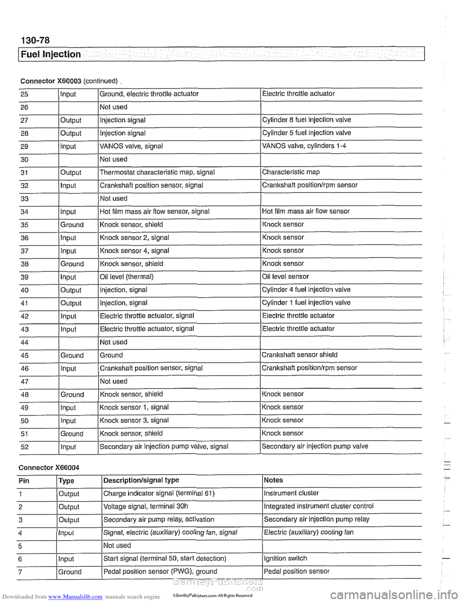
Connector X60003 (continued) Electric throttle actuator
25
- 27 28
29
30
31
32
33
I I I
36 jlnput I Knoclc sensor 2, signal 1 Knock sensor
I I I
Input
26
Output
Output
input
Output
Input
I ' I . I
43 1 ln~ut I Electric throttle actuator, signal (Electric throttle actuator
Ground, electric throttle actuator
1 Not
used
Hot film mass air flow sensor
34
- 37
38
39
40
41
42
injection signal
Injection
signal
VANOS valve, signal
Not used
Thermostat characteristic map, signal
Crankshaft position sensor, signal
Not used
35 l~round I~nock sensor, shield 1 ~nock sensor
Cylinder
8 fuel injection valve
Cylinder
5 fuel injection valve
VANOS valve, cylinders
1-4
Characteristic map
Crankshaft positionlrpm sensor
input
input
Ground
Input
Output
Output
Innut
Hot film mass air flow sensor, signal
I
44
45 46
47
48
49
50
51
52
Connector )(GO004
Knock sensor 4, signal
Knock sensor, shield
Oil
level (thermal)
Injection, signal
Injection, signal
Electric throttle actuator, signal
Not used
Ground
Crankshaft position sensor, signal
Not used
Knoclc sensor, shield
Knock sensor
1, signal
Knock sensor
3, signal
Knock sensor, shield
Secondary air injection pump valve, signal
'
Ground
Input
Ground
input Input
Ground
Input
I' I ... I . ~
Knock sensor
Knocic sensor
Oil level sensor
Cylinder
4 fuel injection valve
Cylinder
1 fuel injection valve
Electric throttle actuator
Crankshaft sensor shield
Crankshaft
positionlrprn sensor
Knock sensor
Knock sensor
Knock sensor
Knock sensor
Secondary air injection pump valve
Notes
Instrument cluster
Integrated instrument cluster control
Secondary air injection pump
relay
Pin
1
2
3
Electric (auxiliary) cooling fan 4
Type
Output
Output
Outout
Descriptionlsignal type
Charge indicator signal (terminal
61)
Voltage signal, terminal 30h
Secondam air pump relay, activation
Input
5
Signal, electric (auxiliary) cooling fan, signal
I~ot used
Page 469 of 1002
Downloaded from www.Manualslib.com manuals search engine
Fuel Injection I
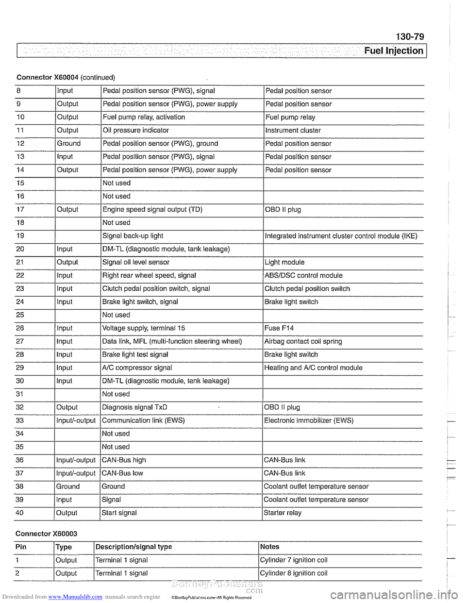
Connector X60004 (continued)
8 10
11
12
13
14
15
16
9
Output 0
Input
17
18
19
20
21
22
23
24
25
26
27
28
29
30
31
32
33
34
35
36
39
llnput lsignal l~oolant outlet temperature sensor
Output
Output
Ground
Input
Output
I I - I
40 /output Istart signal Istarter relay
Pedal position sensor (PWG), signal
Output Input
Output
input
Input
Input
Input
Input
Input
input
Input
Output
Input/-output
Input/-output
37
Connector X60003
Pedal position sensor
Fuel pump relay, activation
Oil pressure indicator Pedal position sensor (PWG), ground
Pedal position sensor (PWG), signal
Pedal position sensor (PWG), power supply
Not used
Not used Fuel
pump relay
Instrument cluster
Pedal position sensor
Pedal position sensor
Pedal position sensor
Engine speed signal output (TD)
Not used
Signal
back-up light
DM-TL (diagnostic module,
tank leakage)
Signal oil level sensor
Right rear wheel speed, signal
Clutch pedal position switch, signal
Brake light switch, signal
Not used
Voltage supply, terminal
15
Data link, MFL (multi-function steering wheel)
Brake light test signal
AJC compressor signal
DM-TL (diagnostic module, tank
leakage)
Not used
Diagnosis signal
TxD
Communication link (EWS)
Not used
Not used
CAN-BUS hiqh
38 1 Ground l~round I Coolant outlet temperature sensor
OED II plug
Integrated instrument cluster control module (IKE)
Light module
ABSIDSC control module
Clutch pedal position switch
Brake light switch
Fuse
F14
Airbag contact coil spring
Brake light switch
Heating and
A/C control module
OBD
II plug
Electronic immobilizer (EWS)
CAN-Bus link
CAN-Bus link
Input/-output CAN-Bus low
Page 470 of 1002

Downloaded from www.Manualslib.com manuals search engine
Fuel Injection
Connector X60005 (continued)
I I I
6 /output l~erminal 1 signal ICylinder 1 ignition coil
Cylinder
2 ignition
coil
Cylinder
3 ignition coil
Ground point
3
4
5
7
8 -- 9
Output
Output
Ground Terminal 1 signal
Terminal
1 signal
Ground
Output
Output
Output Terminal
1 signal
Terminal
1 signal
p
Cylinder 4 ignition coil
Cylinder
5 ignition coil
Cylinder
6 ignition coil
Page 501 of 1002
Downloaded from www.Manualslib.com manuals search engine
170-5
Radiator and Cooling System
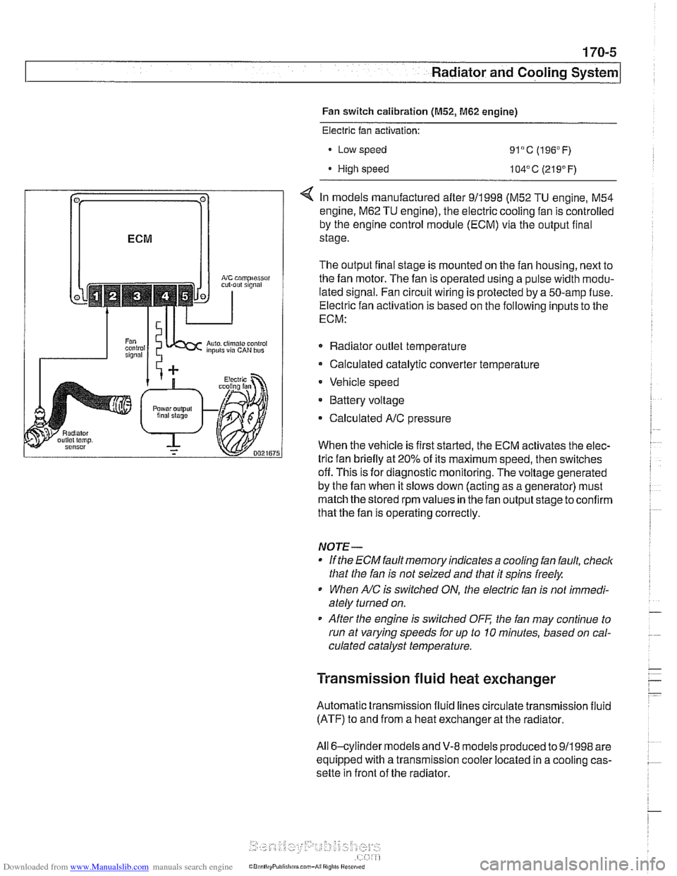
Fan switch calibration (M52, M62 engine)
coniprairoi OUt rlgnal
Auto. ciimilte ~ontioi inpuls via CAN bus
Electric fan activation:
Low speed
91°C (196°F)
High speed 104' C (21 9' F)
< In models manufactured after 911998 (M52 TU engine, M54
engine.
M62 TU engine), the electric cooling fan is controlled
by the engine control module (ECM) via the output final
stage.
The output final stage is mounted on the fan housing, next to
the fan motor. The fan is operated using a pulse width modu-
lated signal. Fan circuit wiring is protected by a 50-amp fuse.
Electric fan activation is based on the following inputs to the
ECM:
Radiator outlet temperature
Calculated catalytic converter temperature
Vehicle speed
* Battery voltage
Calculated
A/C pressure
When the vehicle is first started, the ECM activates the elec-
tric fan briefly at 20% of its maximum speed, then switches
off. This is for diagnostic monitoring. The voltage generated
by the fan when it slows down (acting as a generator) must
match the stored rpm values in the fan output stage toconfirm
that the fan is operating correctly.
NOTE-
If the ECM fault memory indicates a cooling fan fault, check
that the fan is not seized and that it spins freely.
When
A/C is switched ON, the electric fan is not immedi-
ately turned on.
After the engine is switched
OFF the fan may continue to
run at varying speeds for up to 10 minutes, based on cal-
culated catalyst temperature.
Transmission fluid heat exchanger
Automatic transmission fluid lines circulate transmission fluid
(ATF) to and from a heat exchanger at the radiator.
All 6-cylinder
models andV-8 models produced to 911998 are
equipped with a transmission cooler located in a cooling cas-
sette in front of the radiator.
Page 743 of 1002
Downloaded from www.Manualslib.com manuals search engine
330-47
Rear suspension/
Ride height sensor, removing and installing
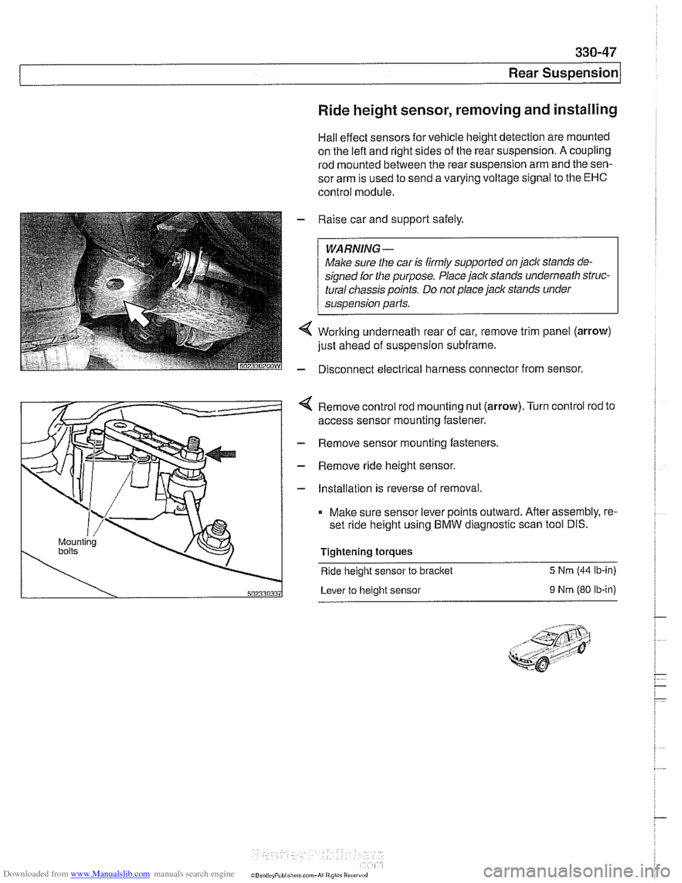
Hall effect sensors for vehicle height detection are mounted
on the
left and right sides of the rear suspension. A coupling
rod mounted between the rear suspension arm and the sen-
sor arm is used to send a varying voltage signal to the
EHC
control module.
Raise car and support safely.
WARNING-
Male sure the car is firmly supported on jaclc stands de-
signed
for the purpose. Place jaclc stands underneath struc-
tural chassis points. Do not place jaclc stands under
sus~ension Darts.
Working underneath rear of car, remove trim panel (arrow)
just ahead of suspension subframe.
Disconnect electrical harness connector from sensor.
4 Remove control rod mounting nut (arrow).Turn control rod to
access sensor mounting fastener.
- Remove sensor mounting fasteners.
- Remove ride height sensor.
- Installation is reverse of removal.
Make sure sensor lever points outward. After assembly, re-
set ride height using BMW diagnostic scan tool DIS.
Tightening torques
Ride
height sensor to bracket 5 Nrn (44 lb-in)
Lever to height sensor
9 Nrn (80 ib-in)
Page 800 of 1002
Downloaded from www.Manualslib.com manuals search engine
.
I Body-General 1
Rear wiper system
The rear wiper assembly on the E39 Sport Wagon is a self-
contained unit. The control electronics are integrated into the
gear drive that is part of the motor assembly. The control elec-
tronics contain two hall sensors, one
forthe park position and
one
forthe end stop or to signal reverse direction of the wiper
motor.
-
Wiperlwasher
stalk switch
/ 4 - 3
502400100
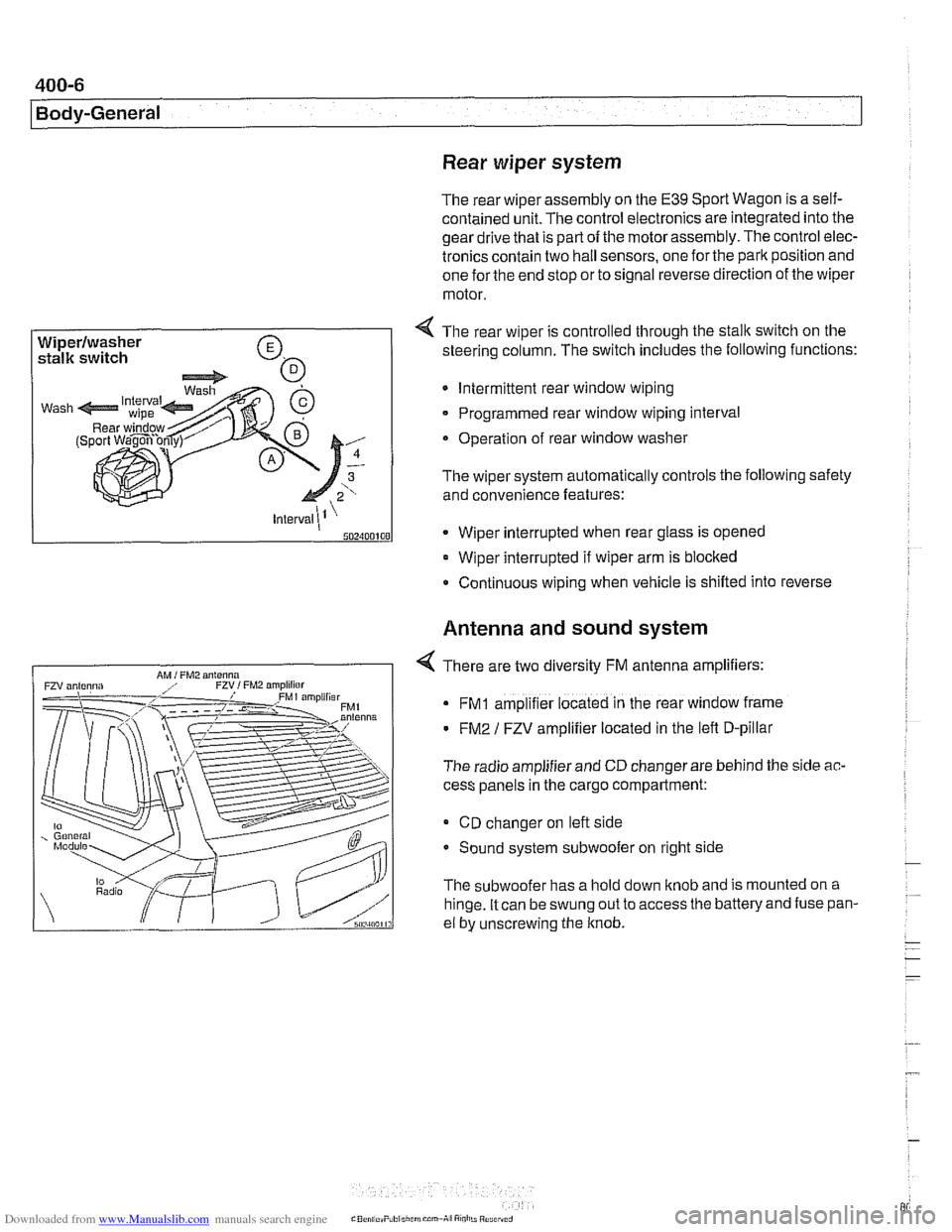
4 The rear wiper is controlled through the stalk switch on the
steering column. The switch includes the following functions:
Intermittent rear window wiping
Programmed rear window wiping interval
Operation of rear window washer
The wiper system automatically controls the following safety
and convenience features:
* Wiper interrupted when rear glass is opened
Wiper interrupted if wiper arm is blocked
Continuous wiping when vehicle is shifled into reverse
Antenna and sound system
4 There are two diversity FM antenna amplifiers:
FMI amplifier located in the rear window frame
FM2 / FZV amplifier located in the lefl D-pillar
The radio amplifier and CD changer are behind the side
ac-
cess panels in the cargo compartment:
CD changer on lefl side
Sound system subwoofer on right side
The subwoofer has a hold down knob and is mounted on a
hinge. It can be swung out to access
the batteryand fuse pan-
el by unscrewing the knob.
Page 803 of 1002
Downloaded from www.Manualslib.com manuals search engine
400-9
Body-General
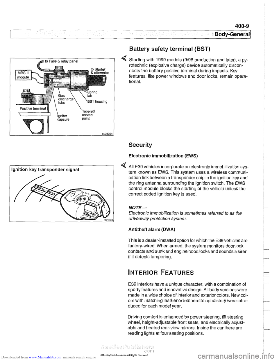
Battery safety terminal
(BST)
4 Starting with 1999 models (9198 production and later), a py-
rotechnic (explosive charge) device automatically discon-
nects the battery positive terminal during impacts. Key
features,
like power windows and door locks, remain opera-
tional.
Security
Electronic immobilization (EWS)
Ignition key transponder signal All
E39 vehicles incorporate an electronic immobilization sys-
tem known as EWS. This svstem uses a wireless comrnuni-
cation link between a transponder chip in the ignition key and
the ring antenna surrounding the ignition switch. The EWS
control module blocks the starting of the vehicle unless the
correct coded ignition key is used.
NOTE-
Electronic immobilization is sometimes referred to as the
driveaway protection system.
Antitheft alarm (DWA)
This is adealer-installed option for which the E39 vehicles are
factory-wired. When armed, the system monitors door
loci(
contacts and trunk and engine hood locks and sounds a siren
if it detects tampering.
E39 interiors have a unique character, with a combination
of
sporty features and innovativedesign. All body versions were
made in a wide choice of interior and exterior colors. New col-
ors with matching leather or leatherette upholstery were intro-
duced for each model year.
Driving
comfort is enhanced by power steering, tilt steering
wheel, height-adjustable front seats, and electrically adjust-
able and heated rear-view mirrors. Inside the car there are
reading lights at four seating positions.