COLD START SENSOR BMW 528i 1998 E39 Workshop Manual
[x] Cancel search | Manufacturer: BMW, Model Year: 1998, Model line: 528i, Model: BMW 528i 1998 E39Pages: 1002
Page 407 of 1002

Downloaded from www.Manualslib.com manuals search engine
Fuel Injection 1
NOTE-
The 1998 5281' with MS 41.1 requires a barometric pressure
sensor input signal for activation of the
LDP check. This sen-
sor is located on the passenger side strut tower
fo~lard of
ABS/ASC hydraulic unit.
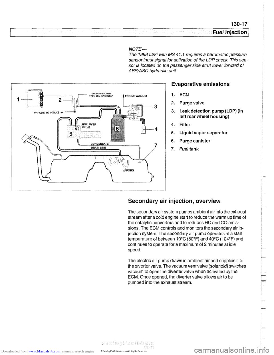
Evaporative emissions
1. ECM
2. Purge valve
3. Leak detection pump (LDP) (in
lefl rear wheel housing)
4. Filter
5. Liquid vapor separator
6. Purge canister
7. Fuel tank
Secondary air injection, overview
The secondary air system pumps ambient air into the exhaust
stream afler a cold engine start to reduce the warm up time of
the catalytic converters and to reduces HC and CO emis-
sions. The ECM controls and monitors the secondary air in-
jection system. The secondary air pump operates at a start
temperature of between 10°C (50°F) and 40°C (104°F) and
continues to operate for a maximum of
2 minutes at idle
speed.
The electric air pump draws in ambient air and supplies it to
the divertervalve. The vacuum ventvalve (solenoid) switches
vacuum to open the divertervalve when activated by the
ECM. Once opened, the diverter valve allows air to be
pumped into the exhaust stream.
Page 965 of 1002

Downloaded from www.Manualslib.com manuals search engine
On-Board Diagnostics
Catalyst monitoring. Thisstrategy monitors the outputofthe
precatalyst and post-catalyst oxygen sensors, comparing the
oxygen content going into the catalytic converter to the
oxygen leaving the converter.
The diagnostic executive
lknows that most of the oxygen
should be used up during the oxidation phase. If it detects
higherthan programmed values, afault is set and the MIL
illuminates.
Misfire detection. This strategy monitors crankshaft speed
fluctuations and determines if an enoine misfire occurs bv
monitoring variations in speed between each crankshaft
sensortrigger point. This strategy is so finely tuned that it can
determine the severity of the misfire.
The system determines
if a misfire is occurring, as well as
other pertinent misfire
information such as:
Specific
cylinder(s)
Severity of the misfire event
Emissions relevant or catalyst damaging
Misfire detection is an on-going monitoring process that is
only disabled under certain limited conditions.
Secondary air injection monitoring. Secondary air
injection is used to reduce HC and CO emissions during
engine warm up. Immediately following a cold engine start
(-1 0" to 40°C), fresh air (and therefore oxygen) is pumped
directly into the exhaust
manifold. By injecting additional
oxygen into the exhaust manifold, catalyst warm-up time is
reduced.
Secondary air system components are:
Electric air injection pump
* Electric pump relay
* Non-return valve
Vacuum
I vent valve
- Stainless steel air injection pipes
Vacuum reservoir
The secondary air system is monitored via the use
of the pre-
catalyst oxygen sensors. Once the air pump is active and air
is injected into the system, the signal at the oxygen sensor
reflects a lean condition. If the oxygen sensor signal does not
change, a fault is set and the faulty
bank(s) identified. If after
completing the next cold startafault is again present, the MIL
illuminates.
Page 966 of 1002

Downloaded from www.Manualslib.com manuals search engine
OBD-6
On-Board Diagnostics
Fuel system monitoring. This monitor looks at the fuel
delivery needed (long
/short term fuel trim) for proper engine
operation based on programmed data. If too much or not
enough fuel is delivered over a predetermined time, a DTC is
set and the MIL illuminates.
Fuel trim refers to adiustments to base fuel schedule.
Lono- ., term fuel trim refers to gradual adjustments to the fuel
calibration adjustment as compared to short term fuel trim.
Long term fuel trim adjustments compensate for gradual
changes that occur over time.
Fuel system monitoring monitors the calculated injection time
(ti) in relation to enginespeed, load and precatalyticconverter
oxygen
sensor(s) signals.
Using this data, the system optimizes fuel delivery for all
engine operating conditions.
Evaporative system monitoring. This monitor checks the
the fuel storage system and related fuel lines for leaks. It can
detect very small leaks anywhere in the system.
A leak detection unit (LDP or DMTL) is used to pressurize the
evaporative control system on a continuous basis (as the
drive cycle allows) and to
check system integrity.
Drive cycle
The OED II drive cycle is an important concept in
understanding OBD
II requirements. The purpose of the drive
cycle is to run ail of the emission-related on-board diagnostics
over a broad range of driving conditions.
A drive cycle is considered complete when all of the
diagnostic monitors have run their tests without interruption.
~ora drive cycle to be initiated, the vehicle must be started
cold and brought up to
1 60°F and at least 40°F above its
original starting temperature.
Readiness codes
Inspection/maintenance (I/M) readiness codes are mandated
as part of OBD
II. The readiness code is stored aftercomplete
diagnostic monitoring of specified components and systems
is carried out. The readiness code function was designed to
prevent manipulating an
I/M emission test procedure by
clearing faults codes or disconnecting the ECM or battery.