Cooling fan BMW 528i 1998 E39 Workshop Manual
[x] Cancel search | Manufacturer: BMW, Model Year: 1998, Model line: 528i, Model: BMW 528i 1998 E39Pages: 1002
Page 34 of 1002
Downloaded from www.Manualslib.com manuals search engine
020-2
Maintenance
The information given in this repair group includes the routine
checlts and maintenance steps that are both required by
BMW under the terms of the vehicle warranty protection and
recommended by BMW to ensure long and reliable vehicle
operation.
NOTE-
Aside from keeping your car in the best possible condition,
proper maintenance plays a role in maintaining full protection
under
BMW's new car warranty coverage. If in doubt about
the terms and conditions of your car's warranty, an autho-
rized BMW dealer should be able to explain them to you.
Special tools
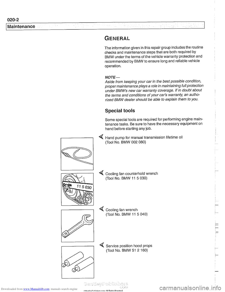
Some special tools are required for performing engine main-
tenance tasks. Be sure to have the necessary equipment on
hand before starting any job.
4 Hand pump for manual transmission lifetime oil
71 (Tool No. BMW 002 080)
4 Cooling fan counterhold wrench
(Tool No. BMW 11 5 030)
I I 4 Coolina fan wrench
I
4 Service position hood props
(Tool No. BMW 51 2 160)
Page 48 of 1002
Downloaded from www.Manualslib.com manuals search engine
020-1 6
Maintenance
loose, hose is damaged, or connection is dirty or corroded.
Dried coolant has achalky appearance. Hoses should be firm
and springy. Replace any hose that is cracked, has become
soft and limp, or has been contaminated by oil.
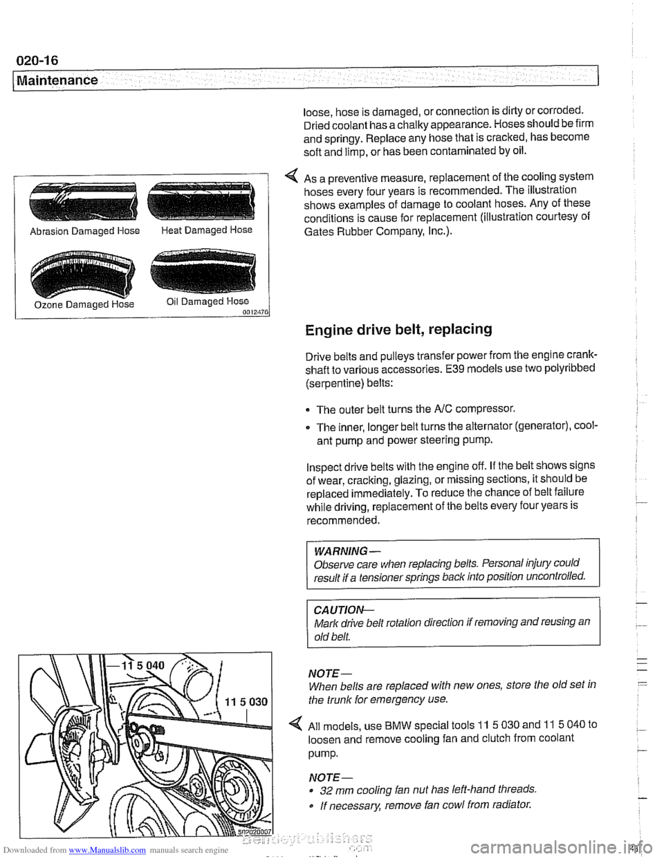
4 As a preventive measure, replacement of the cooling system
hoses every four years is recommended. The illustration
shows examples of damage to coolant hoses. Any of these
conditions is cause for replacement (illustration courtesy of
/ Abrasion Damaged Hose Heat Damaged Hose 1 Gates Rubber Company, I~c.).
Engine drive belt, replacing
Drive belts and pulleys transfer power from the engine crank-
shaft to various accessories.
E39 models use two polyribbed
(serpentine) belts:
The outer belt turns the
NC compressor.
0 The inner, longer belt turns the alternator (generator), cool-
ant pump and power steering pump.
Inspect drive belts with the engine off. If the belt shows signs
of wear, cracking, glazing, or missing sections, it should be
replaced
immediately. To reduce the chance of belt failure
while driving, replacement of the belts every four years is
recommended.
WARNING -
Observe care when replacing belts. Personal injury could
result if a tensioner springs back into position uncontrolled.
CA UTIOI\C
Mark drive belt rotation direction if removing and reusing an
old belt.
NOTE-
When belts are replaced with new ones, store the old set in
the trunk for emergency use.
All models, use
BMW special tools 11 5 030 and 11 5 040 to
loosen and remove cooling fan and clutch from coolant
pump.
NOTE-
32 mm cooling fan nut has left-hand threads
If necessary, remove fan cowl from radiator.
Page 74 of 1002
Downloaded from www.Manualslib.com manuals search engine
I Engine Removal and Installation
Engine removal and installation are covered in this repail
group.
See 100 Engine-General for engine identification details
and engine codes.
Transmission removal is required for all models before the
engine can be removed. This is best accomplished with the
car raised on an automotive lift. For additional procedures re-
quired during engine removal, refer to the following repair
groups:
020 Maintenance
0 121 Battery, Alternator, Starter
170 Radiator and Cooling System
180 Exhaust System
4 230 Manual Transmission
0 240 Automatic Transmission
410 Fenders, Engine Hood
Special tools
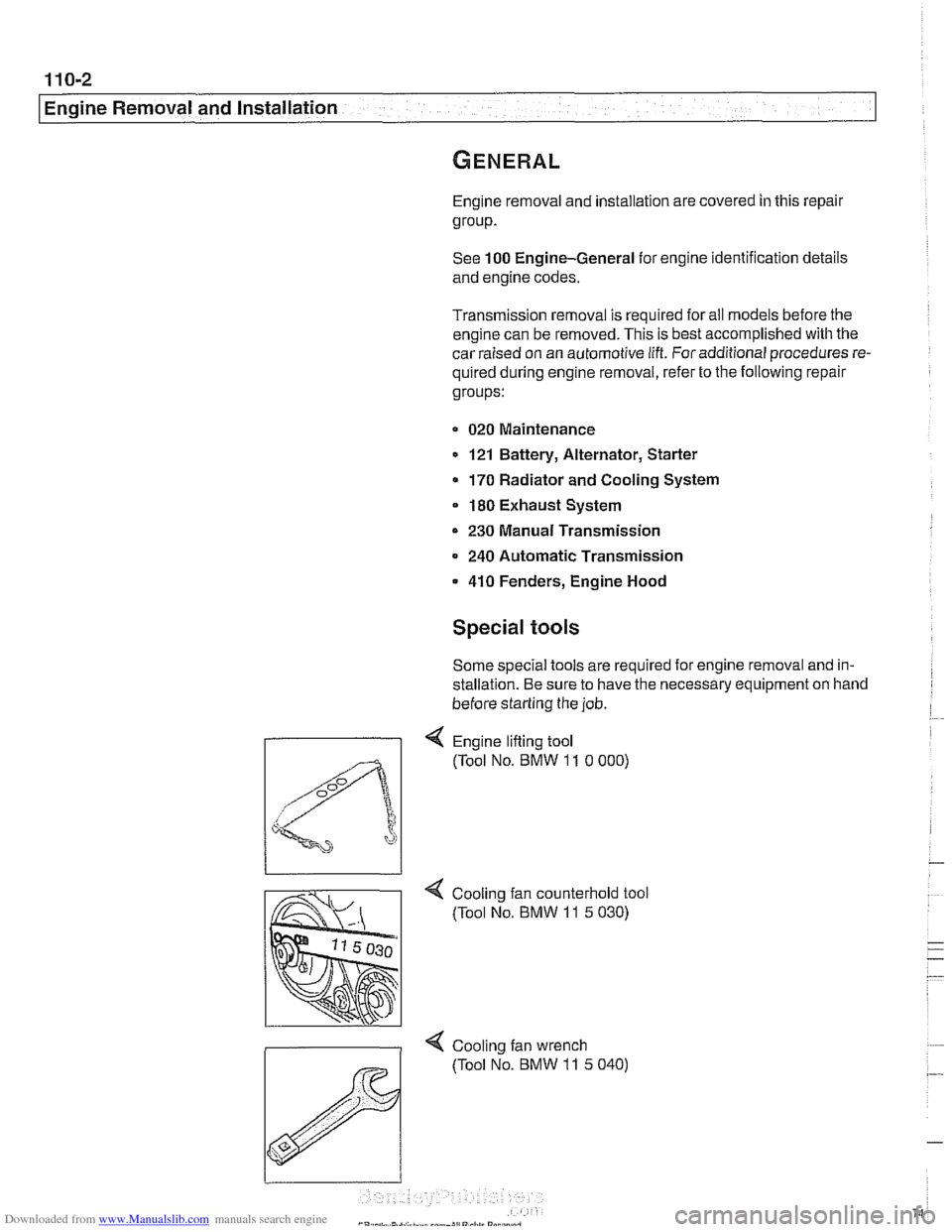
Some special tools are required for engine removal and in-
stallation. Be sure to have the necessary equipment on hand
before starting the job.
Engine lifting tool
(Tool No. BMW
11 0 000)
4 Cooling fan counterhold tool
(Tool No. BMW
11 5 030)
< Cool~ng fan wrench
(Tool No. BMW
11 5 040)
Page 84 of 1002
Downloaded from www.Manualslib.com manuals search engine
110-12
Engine Removal and Installation
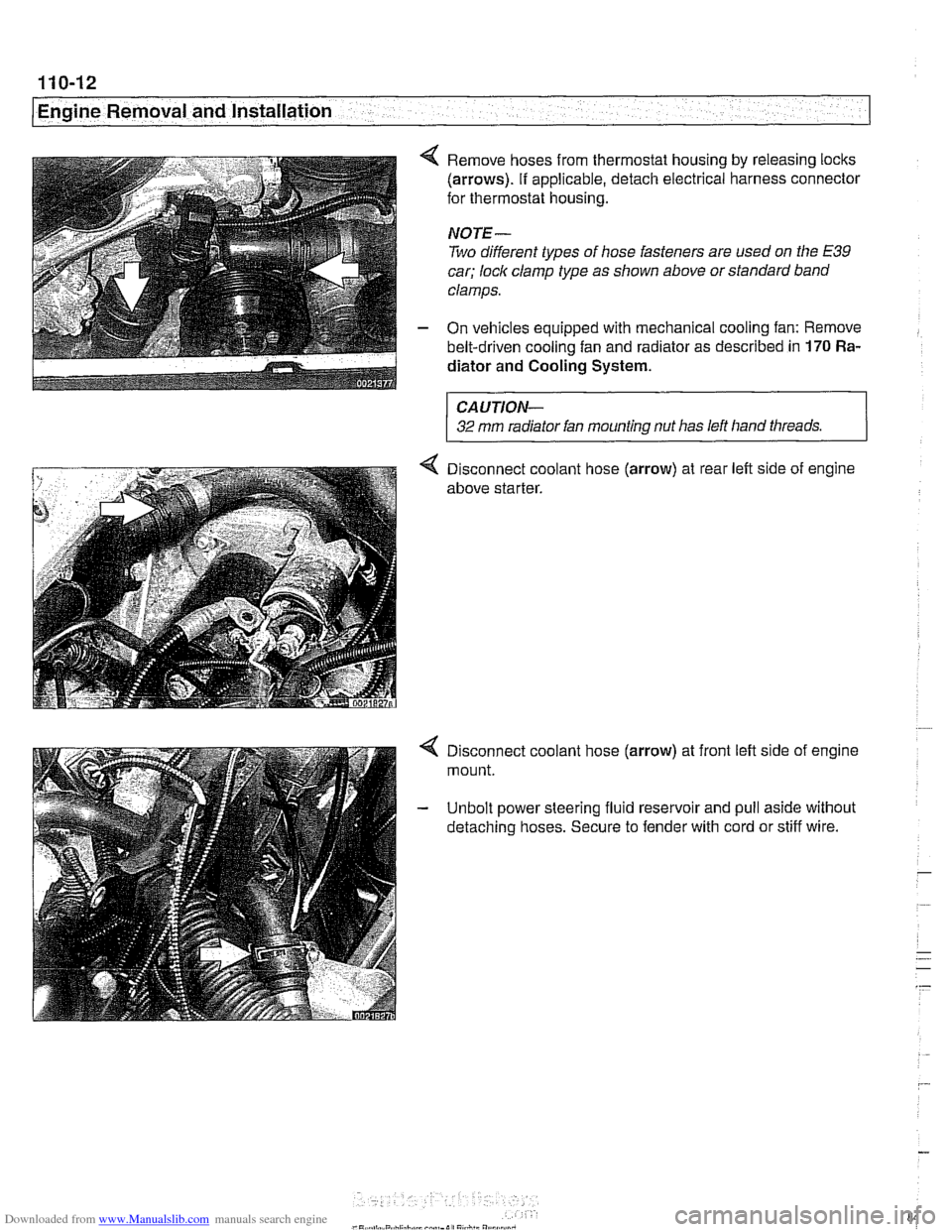
4 Remove hoses from thermostat housing by releasing locks
(arrows). If applicable, detach electrical harness connector
for thermostat housing.
NOTE-
Two different types of hose fasteners are used on the E39
car; lock clamp type as shown above or standard band
clamps.
- On vehicles equipped with mechanical cooling fan: Remove
belt-driven cooling fan and radiator as described in
170 Ra-
diator and Cooling
System.
CAUTION-
32 mm radiator fan mounting nut has left hand threads.
4 Disconnect coolant hose (arrow) at rear left side of engine
above starter.
4 Disconnect coolant hose (arrow) at front left side of engine
mount.
- Unbolt power steering fluid reservoir and pull aside without
detaching hoses. Secure to fender with cord or stiff wire.
Page 87 of 1002
Downloaded from www.Manualslib.com manuals search engine
110-15
Engine Removal and lnstallation
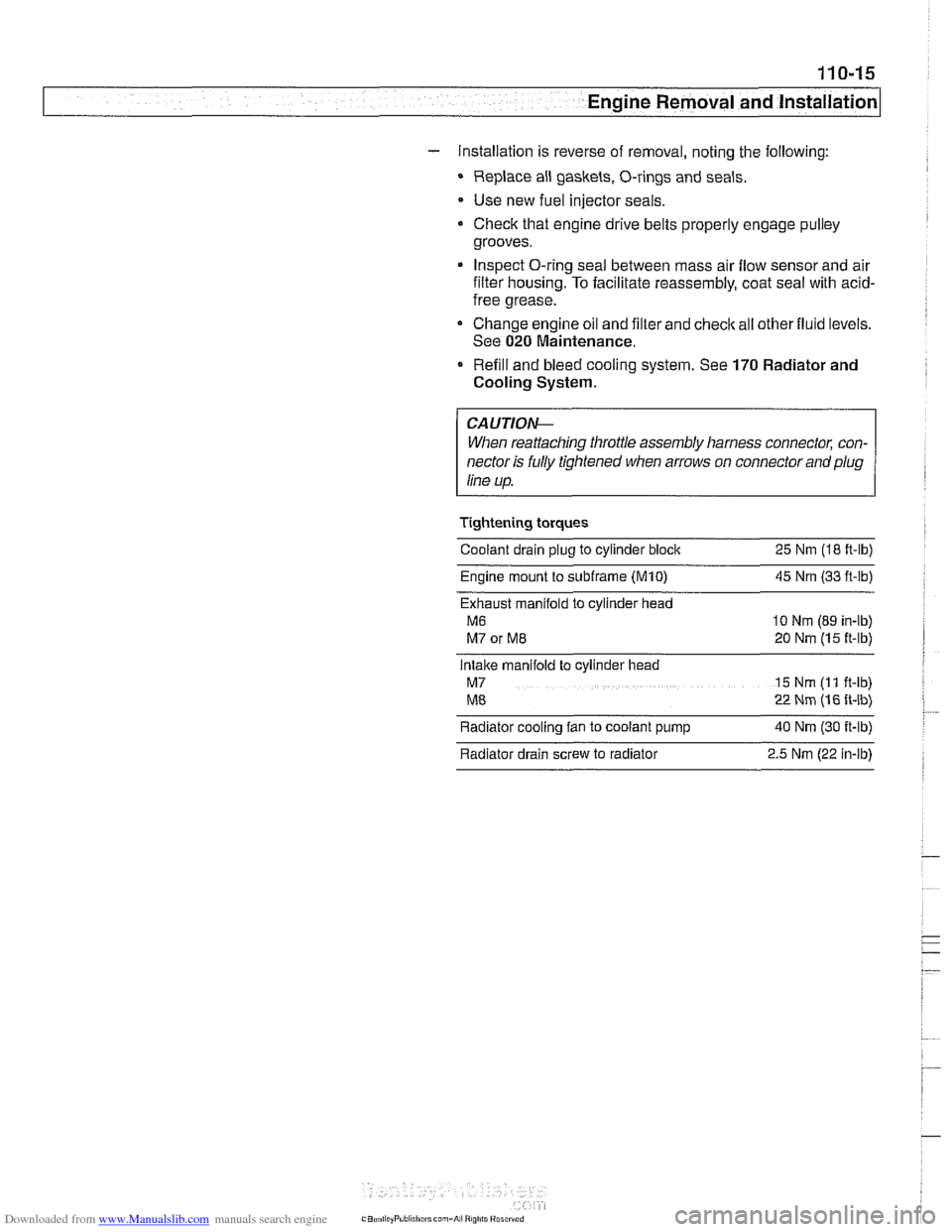
- Installation is reverse of removal, noting the following:
Replace all gaskets. O-rings and seals.
Use new fuel injector seals
Check that engine drive belts properly engage pulley
grooves.
Inspect O-ring seal between mass air flow sensor and air
filter housing. To facilitate reassembly, coat seal with acid-
free grease.
Change engine oil and filter and
check all other fluid levels.
See
020 Maintenance.
Refill and bleed cooling system. See
170 Radiator and
Cooling System.
CAUTION--
When reattaching throttle assembly harness connectoc con-
nector is
fuNy tightened when arrows on connector and plug
line up.
Tightening torques
Coolant drain plug to cylinder block
25 Nm (18 ft-lb)
Engine mount to
subframe (M10) 45 Nm (33 ft-ib)
Exhaust manifold to cylinder head
M6 10 Nm (89 in-lb)
M7 or ME 20 Nm (15 ft-lb)
Intake manifold to cylinder head
M7 15 Nm (I 1 ft-lb)
ME 22 Nm (16 ft-lb)
Radiator cooling fan to coolant pump
40 Nm (30 ft-lb)
Radiator drain screw to radiator
2.5 Nm (22 in-lb)
Page 92 of 1002
Downloaded from www.Manualslib.com manuals search engine
11 0-20
Engine Removal and Installation
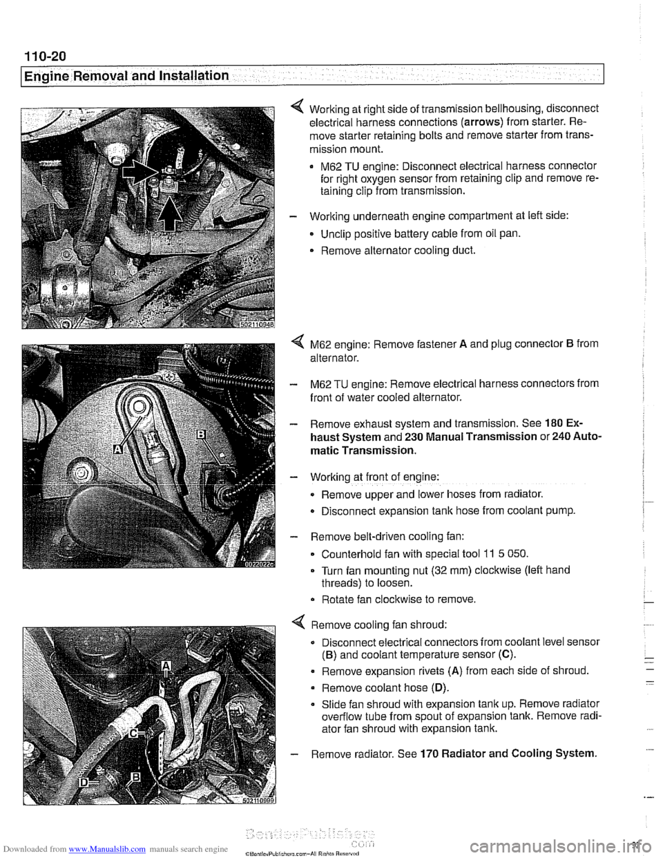
Working at right side of transmission bellhousing, disconnect
electrical harness connections (arrows) from starter. Re-
move starter retaining bolts and remove starter from trans-
mission mount.
M62 TU engine: Disconnect electrical harness connector
for right oxygen sensor from retaining clip and remove re-
taining clip from transmission.
- Working underneath engine compartment at left side:
Unclip positive battery cable from oil pan.
. Remove alternator cooling duct.
4 M62 engine: Remove fastener A and plug connector B from
alternator.
- M62 TU engine: Remove electrical harness connectors from
front of water cooled alternator.
- Remove exhaust system and transmission. See 180 Ex-
haust System and 230 Manual Transmission or 240 Auto-
matic Transmission.
- Working at front of engine:
Remove upper and lower hoses from radiator.
D~sconnect expansion tank hose from coolant pump.
- Remove belt-driven cooling fan:
Counterhold fan with special tool
11 5 050.
Turn fan mounting nut (32 mm) clockwise (left hand
threads) to loosen.
Rotate fan clockwise to remove.
Remove cooling fan shroud:
Disconnect electrical connectors from coolant level sensor
(B) and coolant temperature sensor (C).
. Remove expansion rivets (A) from each side of shroud
Remove coolant hose
(D).
Slide fan shroud with expansion tank up. Remove radiator
overflow tube from spout of expansion tank. Remove radi-
ator fan shroud with expansion tank.
Remove radiator. See
170 Radiator and Cooling System.
Page 94 of 1002
Downloaded from www.Manualslib.com manuals search engine
Engine Removal and Installation
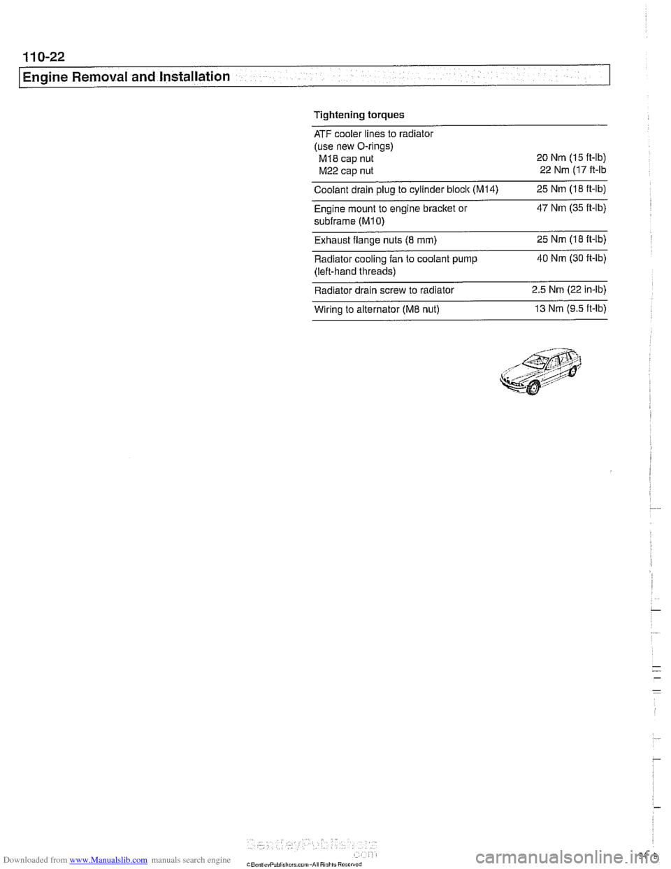
Tightening torques
ATF cooler lines to radiator
(use new O-rings)
MI8 cap nut 20 Nm (15 ft-lb)
M22 cap nut
22
Nm (17 ft-lb
Coolant drain plug to cylinder
blocic (M14) 25 Nm (18 ft-lb)
Engine mount to engine bracket or 47 Nm (35 ft-lb)
subframe (M10)
Exhaust flange nuts (8 mm) 25 Nm (18 ff-ib)
Radiator cooling fan to coolant pump 40 Nm (30 ft-lb)
(left-hand threads)
Radiator drain screw to radiator 2.5 Nm (22 in-lb)
Wirino to alternator
(ME nut) 13 Nm (9.5 ft-lb)
Page 105 of 1002
Downloaded from www.Manualslib.com manuals search engine
..
Cylinder Head Removal and Installation 1
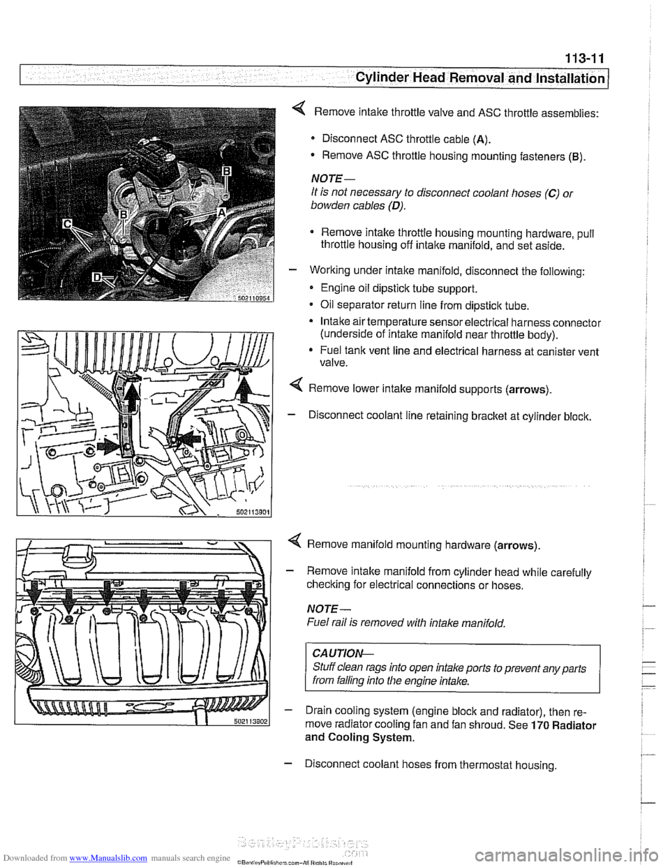
< Remove intake throttle valve and ASC throttle assemblies:
Disconnect ASC throttle cable
(A).
- Remove ASC throttle housing mounting fasteners (B).
NOTE-
It is not necessary to disconnect coolant hoses (C) 01
bowden cables (D).
Remove intake throttle housing mounting hardware, pull
throttle housing off
intake manifold, and set aside.
- Working under intake manifold, disconnect the following:
Engine oil dipstick tube support.
Oil separator return line from dipstick tube.
Intake air temperature sensor electrical harness connector
(underside of intake manifold near throttle body).
* Fuel tank vent line and electrical harness at canister vent
valve.
Remove lower intake manifold supports (arrows).
- Disconnect coolant line retaining bracket at cylinder block.
4 Remove manifold mounting hardware (arrows).
- Remove intake manifold from cylinder head while carefully
checking for electrical connections or hoses.
NOTE-
Fuel rail is removed with intake manifold,
CAUTIOI\C
Stuff clean rags into open intake ports to prevent any parts
from falling into
Nie engine intake.
- Drain cooling system (engine block and radiator), then re-
move radiator cooling fan and fan shroud. See
170 Radiator
and Cooling System.
- Disconnect coolant hoses from thermostat housing.
Page 115 of 1002
Downloaded from www.Manualslib.com manuals search engine
- -.
Cylinder Head Removal and lnstallation
NOTE-
Be Sure the secondary timing chain tensioner is locked down
and the exhaust
camshaif mounting bolts are loose before
proceeding.
- Install VANOS control unit. See VANOS control unit, install-
ing
(M52 engine) in 117 Camshaft Timing Chain.
CAUTION--
Incorrect installation ofthe VANOS control may result in dam-
age to the engine valvefrain.
- Install exhaust manifolds using new gaskets and nuts. Coat
manifold studs with copper paste prior to installing nuts.
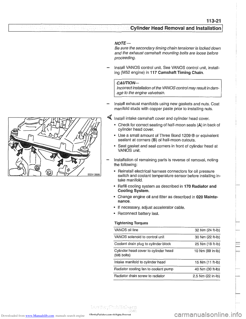
Install intake camshaft cover and cylinder
head cover.
Check for correct seating of half-moon seals
(A) in back of
cylinder head cover.
Use a small amount of Three Bond 1209
O or equivalent
sealant at corners
(6) of half-moon cutouts.
Seat gasket and seal corners in front of cylinder head at
VANOS unit.
- Installation of remaining parts is reverse of removal, noting
the following:
Reinstall electrical harness connectors for oil pressure
switch and coolant temperature sensor before installing in-
take manifold.
Refill cooling system as described in 170 Radiator and
Cooling System.
Change engine oil and filter as described in 020 Mainte-
nance.
If necessary, adjust accelerator cable.
Reconnect battery last.
Tightening Torques
VANOS oil line
32 Nm (24
ft-lb)
VANOS solenoid to control unit 30 Nm (22 ft-lb)
Coolant drain plug to cylinder
block 25 Nm (18 ft-lb)
Cylinder head cover to cylinder head
10 Nrn (89 in-lb)
(M6 bolts)
intake manifold to cylinder head 15 Nm (I 1 ft-lb)
Radiator cooling fan to coolant pump
40 Nm (30 ft-lb) - . .
Radiator drain screw to radiator 2.5 Nm (22 in-lbl
Page 122 of 1002
Downloaded from www.Manualslib.com manuals search engine
I Cylinder Head Removal and Installation
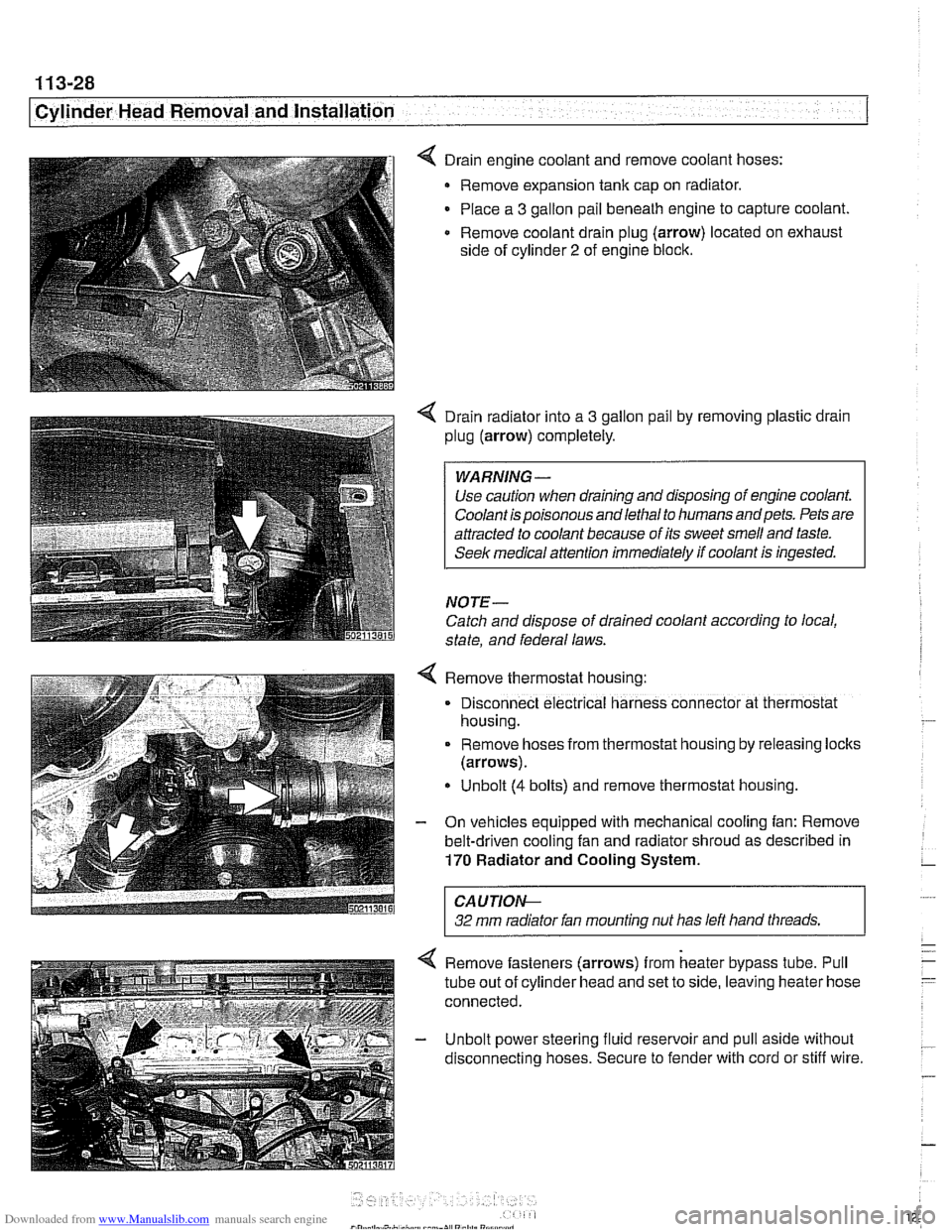
4 Drain engine coolant and remove coolant hoses:
Remove expansion tank cap on radiator.
Place a
3 gallon pail beneath engine to capture coolant
Remove coolant drain plug (arrow) located on exhaust
side of cylinder
2 of engine block.
4 Drain radiator into a 3 gallon pail by removing plastic drain
plug (arrow) completely.
Use caution when draining and disposing of engine coolant.
Coolant is poisonous andlethal to humans andpets. Pets are
attracted to coolant because of its sweet smell and taste.
Seek medical
attention immediately if coolant is ingested.
NOTE-
Catch and dispose of drained coolant according to local,
state, and federal laws.
4 Remove thermostat housing:
. Disconnect electrical harness connector at thermostat
housing.
. Remove hoses from thermostat hous~ng by releasing loclts
(arrows).
Unbolt
(4 bolts) and remove thermostat hous~ng.
- On vehicles equipped with mechanical cooling fan: Remove
belt-driven cooling fan and radiator shroud as described in
170 Radiator and Cooling System.
CAUTIOI\C
32 mm radiator fan mounting nut has left hand threads. r
4 Remove fasteners (arrows) from heater bypass tube. Pull
tube out of cylinder head and set to side, leaving heater hose
connected.
- Unbolt power steering fluid reservoir and pull aside without
disconnecting hoses. Secure to fender with cord or stiff wire.