Egr BMW 528i 1998 E39 Workshop Manual
[x] Cancel search | Manufacturer: BMW, Model Year: 1998, Model line: 528i, Model: BMW 528i 1998 E39Pages: 1002
Page 2 of 1002
Downloaded from www.Manualslib.com manuals search engine
--
Benllcy Publishers, a division ol Robcrt Bcnlley, In=. 1734 M~SB~CIIUP~IIS Avenue Cumbitdge. MA02138 USA Information lhat makes 800-423-4885 / 61 7.547.4170 the diiierence"
BentleyPublishe~
Technical contact inlormation I
We :.€ c3me ,o.lr leeooaca. Pieasc. ;Jam 1 cllriecl 00s an0 zoo ions lo our BhFLt/ recnns? o rcdss'un lor~m a1 http://~~~.BentleyPublishere.com
Errata information
We will evaluate submissions and post appropriate editorial
changes online as text errata or tech discussion. Appropriate
errata will be incorporated with the
boolc text in future printings.
Read errata information for this book before beginning work on
your vehicle. See the following web address tor additional
information:
http://unw.BentleyPublishers.com/errata/
WARNING-important safety notice
Do not use this manual unless vou are familiar with basic automotive reoair orocedures and safe
workshoo oracfices. This manual illustrates
the workshop procedures requked formoslservice work. It is not a subsiituti for full and up-to-date information from thevehiclemanufaciurer
or for proper training as an automotive technician. Note that it is not possible for us to anticipate all of the ways or conditions under which
vehicles may be serviced or to provide cautions as to all of the possible hazards that may result.
The vehicle manufacturer will continue to issue service information updates and parls retrofits
after the editorial closing of this manual. Some
of lhese updates and retrofits will apply lo procedures and specifications in this manual. We regret that we cannot supply updates to
purchasers of this manual.
We have endeavored to ensure the accuracy
of the information in this manual. Please note, however, that considering the vast quantity and
the complexity of the service information involved, we cannot warrant the accuracy or completeness of the information contained in this
manual.
FOR
THESE REASONS, NEITHER THE PUBLISHER NOR THE AUTHOR MAICES ANY WARRANTIES, EXPRESS OR IMPLIED, THATTHE INFORMATION IN THIS BOOK IS FREE OF ERRORS OR OMISSIONS. AND WE EXPRESSLY DISCLAIM THE IMPLIED WARRANTIES OF MERCHANTABILTTY AN0 OF FITNESS FOR A PARTICULAR PURPOSE, EVEN IFTHE PUBLISHER OR AUTHOR HAVE BEEN ADVISED OFA PARTICULAR PURPOSE, AND EVEN IF A PARTICULAR
1 PURPOSE IS INDICATED IN THE MANUAL. THE PUBLISHER AND AUTHOR ALSO DISCLAIM ALL LlABlLrrY FOR DIRECT. INDIRECT. INCIDENTAL OR 1 I CONSEQUENTIAL DAMAGES THAT RESULT FROM ANY USE OFTHE EXAMPLES, INSTRUCTIONS OR OTHER INFORMATION INTHIS BOOK. IN NO EVENT 1
I Your common sense and oood iudoment are crucial to safe and successful service work. Read orocedures throuoh before startino them. I . -- - -~ ~ ---~. - ~ ~~ Think about whether the condition of your car, &r level of mechanical skill, or your level of reading compreh&sion might resill in or
contribute in some way to an occurrence which might cause you injuly, damage your car, or result in an unsafe repair. If you have doubts
for these or other reasons about your ability to pelform safe repair work on your car, have the work done at an authorized BMW dealer or
other qualified shop.
Part numbers listed in this manual are for identification purposes only, not for ordering. Always check wilh your authorized BMW dealer to
verify part numbers and availability before beginning service work lhat may require new
park.
Before anempting any work on your BMW, read the 001 General Warnings and Cautions, and any WARNING or CAUTION that
accompanies a procedure in the service manual. Review the WARNINGS and CAUTIONS each time you prepare to work on your BMW.
I Spec a too s req.1 red to perlorm cena n service operations arc oenl fed n the manLa an0 arc recomrnenoeo lor JSC Jse ol loo s olner than those recommended In lh s serv ce manual may be oelnmcnlal lo lrlc car's sale open1 on as rvec as lne salely 01 lne person servcng I the car. I
Copies of this manual may be purchased from most automotive accessories and parts dealers specializing in BMW automobiles, from
selected booksellers, or directly from the publisher.
This manual was published by Robert Bentley,
Inc., Publishers. BMW has not reviewed and does not vouch for the accuracy of the
technical specifications and procedures described in this manuai.
Libratv of Conaress Cataloaino-in-Publication Data " " -
BMW 5 Series (E39) : service manual : 523. 528i, 530i. 540i, sedan, sport wagon, 1997,
1998, 1999,2000,2001,2002
~Acludes index.
ISBN 0-8376-0317-X (obi<) ,, , 1. BMW 5 series automobiles--Maintenance and repair--Handbooks manuals, etc. 1.
Robert Bentley, Inc.
TL215.8258623 2003 629.28'722--dc23 2003052231
Bentley Stock No. 8502
Editorial closing 08/03
090807 10987654
The paper used in this publication is acid
free and meets the requirements of the National Standard for Information Sciences-
Permanence of Paper for Printed Library Materials. @
OCopyright 2007 Robert Bentley. Inc. Bentiey Publishers is a trademark of Robert Bentley, Inc.
All rights reserved. All information contained in this manual is based on the information available to the publisher at the time of editorial
closing. The right is reserved to make changes at any time without notice. No part of this publication may be reproduced, stored in a
retrieval system, or transmitted in any form or by any means, electronic, mechanical, photocopying, recording, or
ofhenvise, without the
prior written consent of the publisher. This includes text, figures, and tables. All rights reserved under Berne and Pan-American Copyright
conventions.
Cover photos of car exteriors by Jonathan Richard for
Bentley Publishers @ Robert Bentley, Inc. Cover design and use of blue band on
spine and back cover are trademarks
of Bentley Publishers. All rights reserved.
Manufactured in the United States of America
Page 51 of 1002
Downloaded from www.Manualslib.com manuals search engine
Maintenance
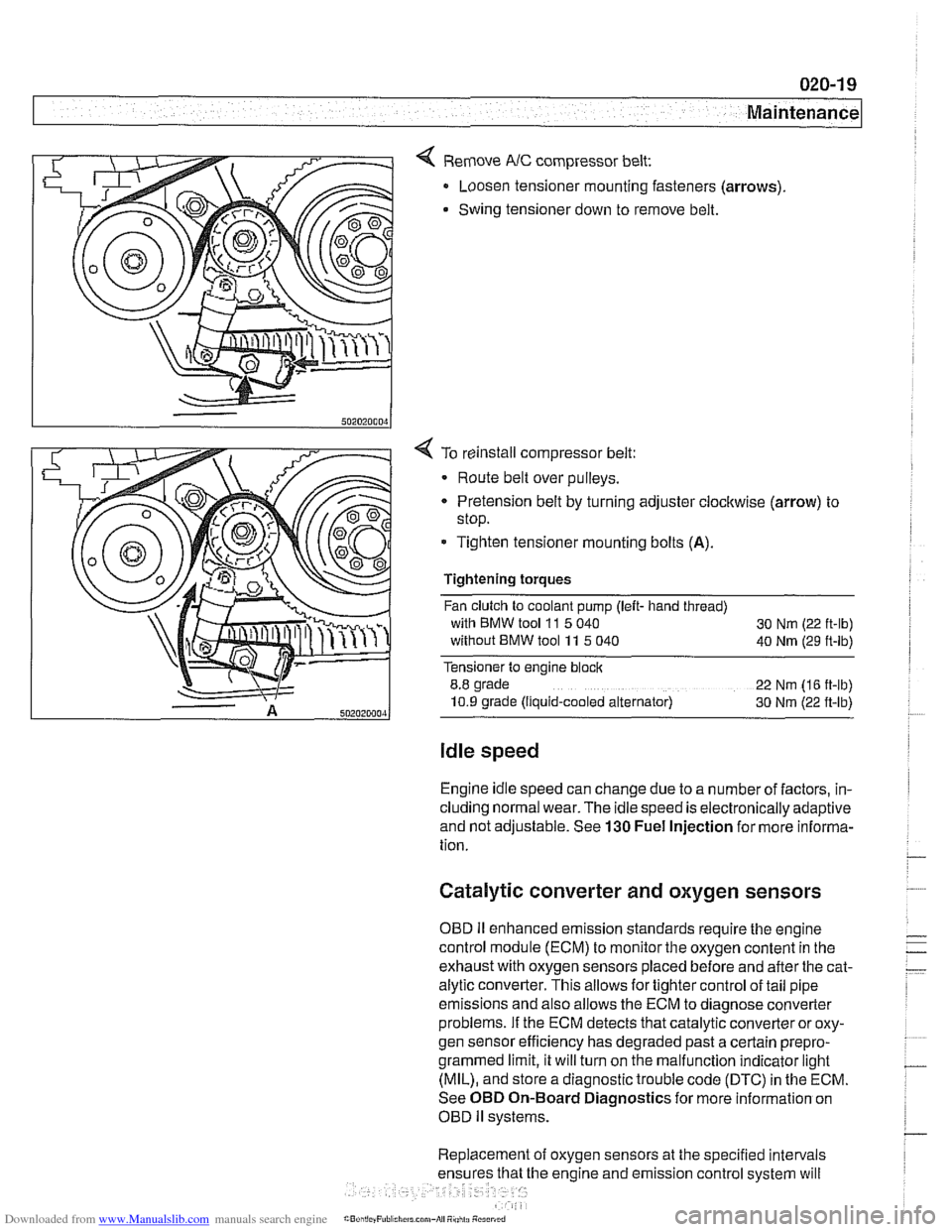
< Remove NC compressor belt:
Loosen tensioner mounting fasteners (arrows)
Swing tensioner down to remove belt.
4 To reinstall compressor belt:
Route belt over pulleys.
* Pretension belt by turning adjuster clockwise (arrow) to
stop.
- Tighten tensioner mounting bolts (A).
Tightening torques
Fan clutch to coolant pump (left- hand thread)
with BMW tool
11 5 040
30 Nm (22 ft-lb)
without BMW tool 11 5 040
40 Nm (29 ft-lb)
Tensioner to engine block
8.8 grade
22 Nm (16 ft-lb)
10.9 grade (Ilquid-cooled alternator) 30 Nm (22 ft-lb)
Idle speed
Engine idle speed can change due to a number of factors, in-
cluding normal wear. The idle speed is electronically adaptive
and not adjustable. See
130 Fuel Injection for more informa-
tion.
Catalytic converter and oxygen sensors
OBD II enhanced emission standards require the engine
control module (ECM) to monitor the oxygen content in the
exhaust with oxygen sensors placed before and after the cat-
alytic converter. This allows for tighter control of tail pipe
emissions and also allows the ECM to diagnose converter
problems. If the ECM detects that catalytic converter or oxy-
gen sensor efficiency has degraded past a certain
prepro-
grammed limit, it will turn on the malfunction indicator light
(MIL), and store a diagnostic trouble code (DTC) in the ECM.
See OBD On-Board Diagnostics for more information on
OBD
ll systems.
Replacement of oxygen sensors at the specified intervals
he engine and emission control system will
Page 63 of 1002
Downloaded from www.Manualslib.com manuals search engine
Maintenance
BODY AND INTERIOR MAINTENANCE
Body and hinges, lubricating
Door locksand loclccylinderscan be lubricated with an oil that
contains graphite.
Body and doorhinges, hood latch and doorcheclc rods should
be lubricated with
SAE 30 or SAE 40 engine oil. Lubricate
seat runners with multipurposegrease. Do not apply any oil to
rubber parts.
If door weather-strips are sticking, lubricate
them with silicone spray or talcum powder. The hood release
cable should be lubricated as well.
The use of winter
lock deicer sprays should be lkept to an
absolute minimum, as the alcohol in the deicer will wash the
grease out of the lock assemblies and may cause locks to
corrode internally or to become difficult to operate.
Exterior washing
The longer dirt is left on the paint, the greater the risk of dam-
aging theglossy finish,
eitherby scratching or by thechemical
effect dirt particles may have on the painted surface.
Do not wash the car in direct sunlight. If the engine hood is
warm, allow it to cool. Beads of water not only leave spots
when dried rapidly by the sun or heat from theengine, but also
can act as small magnifying glasses and burn spots into the
finish. Wash the car with a mixture of lukewarm water and a
car wash product. Rinse using plenty of clear water. Wipe the
body dry with a sofl cloth towel or chamois to prevent
water-spotting.
Interior care
Dirt spots can usually be removed with lultewarm soapy water
or a dry foam cleaner. Use spot remover for grease and oil
spots. Do not pour the liquid directly on the carpet or fabric,
but dampen a clean cloth and rub carefully, starting at the
edge of the spot and working inward. Do not use gasoline,
naphtha, or other flammable substances.
Leather upholstery and trim
Leather upholstery and trim should be periodically cleaned
using a slightly damp cotton or wool cloth. The idea is to get
rid of the dirt in the creases and pores that can cause brittle-
ness and premature aging. On heavily soiled areas, use a
mild detergent (such as
wooliteQ) or other specially formulat-
ed leather cleaners. Dry the trim and upholstery completely
Page 376 of 1002
Downloaded from www.Manualslib.com manuals search engine
121-10
I Battery, Starter, Alternator
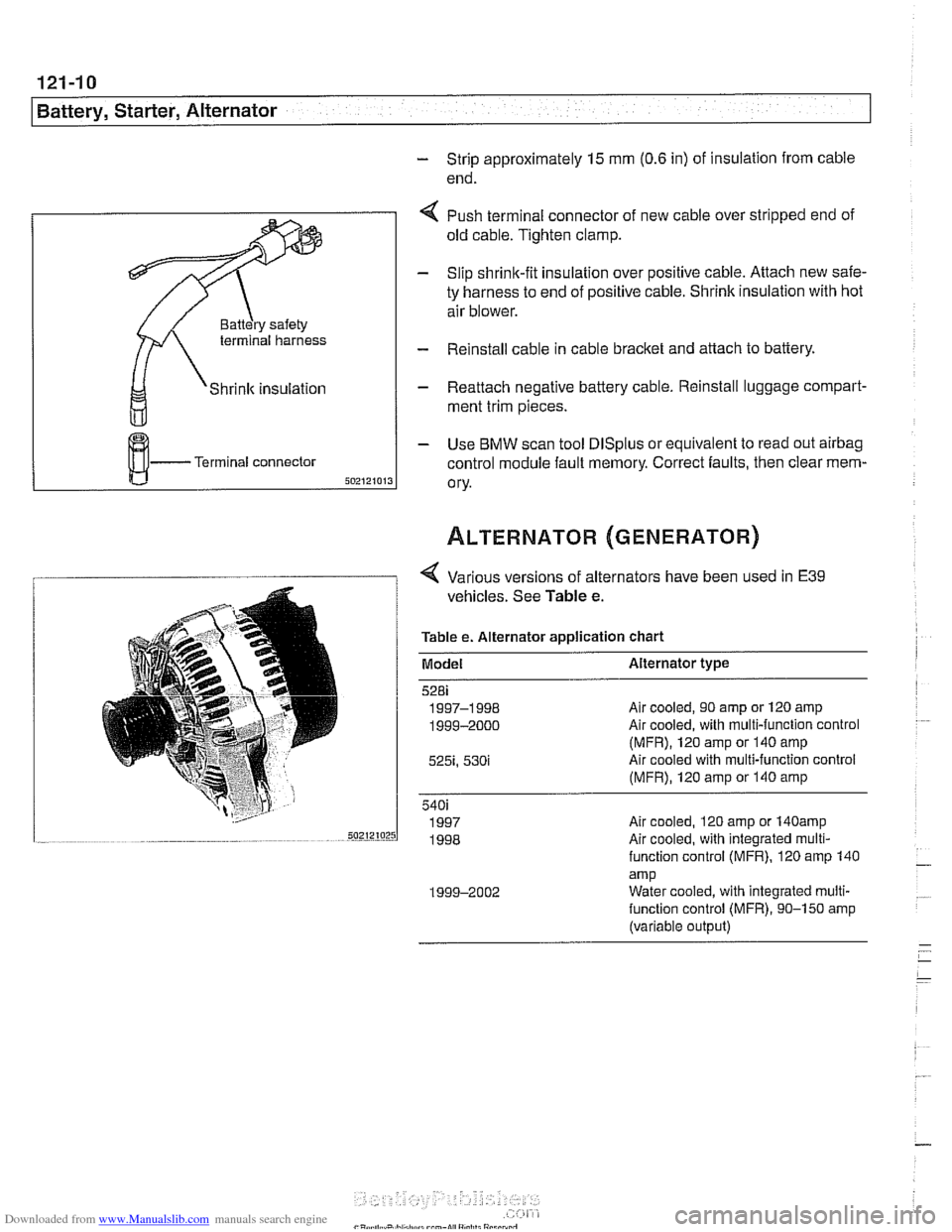
- Strip approximately 15 rnm (0.6 in) of insulation from cable
end.
terminal harness
Shrink insulation
Terminal connector
4 Push terminal connector of new cable over stripped end of
old cable. Tighten clamp.
- Slip shrink-fit insulation over positive cable. Attach new safe-
ty harness to end of positive cable. Shrink insulation with hot
air blower.
- Reinstall cable in cable bracket and attach to battery.
- Reattach negative battery cable. Reinstall luggage cornpart-
rnent trim pieces.
- Use BMW scan tool DlSplus or equivalent to read out airbag
control module fault memory. Correct faults, then clear mem-
ory.
1 1 4 Various versions of alternators have been used in E39
vehicles. See Table e.
Table e. Alternator application chart
Model Alternator type
Air cooled, 90 amp or 120 amp
Air cooled, with multi-function control
(MFR), 120 amp or 140 amp
Air cooled with multi-function control
(MFR), 120 amp or 140 amp
540i 1997 Air
cooled. 120
amp or 140amp sazrz~orsl 1998 ~~~ ~ .~ . ...~ ~ ~-~~~~ Air cooled; with integrated mu~ii-
function control (MFR). 120 amp 140
amp 1999-2002 Water
cooled, with integrated multi-
function control (MFR), 90-150 amp
(variable output)
Page 377 of 1002
Downloaded from www.Manualslib.com manuals search engine
121-11
Battery, Starter, ~lternatorl
Alternator 1997 - 98 5281 1997 540i
/-- -----,
I'
-----------
F15 / 7.5A/ :
&.. .... , 30 1 Xi0015
Battery
Hol in run 61 E (D+) Alternator
and stsrt
lBL
(Generator)
1 .--------,charge , . I , indicator I xGoli i
I <"9,7,a,T
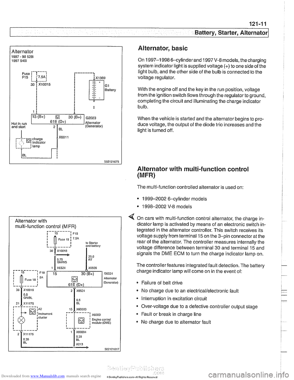
Alternator, basic
On 1997-1 998 6-cylinderand 1997 V-8 models, the charging
system indicator light is supplied voltage
(+) to one side of the
light bulb, and the other side of the bulb is connected to the
voltage regulator.
With the engine off and the key in the run position, voltage
from the ignition switch flows through the regulator to ground,
completing the circuit and illuminating the charge indicator
bulb.
When the vehicle is started and the alternator begins to pro-
duce voltage, the output of the diode trio increases and the
light is turned off.
Alternator with multi-function control
(MFR)
Alternator with multi-function control
(MFR)
The multi-function controlled alternator is used on:
* 1999-2002 6-cylinder models
* 1998-2002 V-8 models
4 On cars with multi-function control alternator, the charge in-
dicator lamp is activated by means of an electronic switch in-
tegrated in the alternator controller. This switch receives its
voltage supply from terminal
15 on the 3-pin connector at the
rear of the alternator. The controller measures internally the
voltage difference between terminal 30 and terminal
15 and
signals the DME ECM to turn the charge indicator lamp on.
The controller features integrated fault detection. The battery
charge indicator lamp will come on in the event of:
* Failure of belt drive
No charge due to an
electrical/electronic fault
Interruption in excitation circuit
Over-voltage due to a defective controller output stage Fault or break in charge line
No charge due to alternator fault
Page 422 of 1002
Downloaded from www.Manualslib.com manuals search engine
Fuel Injection
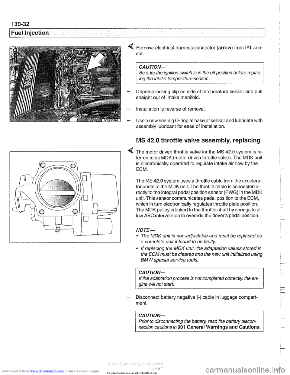
4 Remove electrical harness connector (arrow) from IAT sen-
sor.
CAUTION-
Be sure the ignition switch is in the off position before repiac-
ins the intake temperature sensor.
- Depress loclting clip on side of temperature sensor and pull
straight out of intake manifold.
- Installation is reverse of removal
- Use a new sealing O-ring at base of sensor and lubricate with
assembly lubricant for
ease of installation
MS 42.0 throttle valve assembly, replacing
< The motor driven throttle valve for the MS 42.0 system is re-
- ferred to as MDK (motor driven throttle valve). The MDK unit
is electronically operated to regulate intake air flow by the
ECM.
The
MS 42.0 system uses a throttle cable from the accelera-
tor pedal to the MDK unit. The throttle cable is connected di-
rectly to the integral pedal position sensor
(PWG) in the MDK
unit. This sensor communicates pedal position to the ECM,
which in turn electronically regulates throttle plate position.
The MDK pulley is linked to the throttle shaft by springs to al-
low ASC intervention to override the driver's pedal position.
NO TE -
The MDIC unit is non-adjustable and must be replaced as
a complete unit if found to be faulty.
if replacing the
MDK unit, the adaptation values stored in
the ECM must be clearedand the new unit initialized using
BMW special service tools.
CAUTION-
If the adaptation process is not completed correct& the en-
gine wiii
not start.
- Disconnect battery negative (-) cable in luggage compart-
ment.
CAUTION-
Prior to disconnecting the battern read the battely discon-
nection cautions in
001 General Warnings and Cautions.
Page 437 of 1002
Downloaded from www.Manualslib.com manuals search engine
Fuel Injection
M5.2 system features
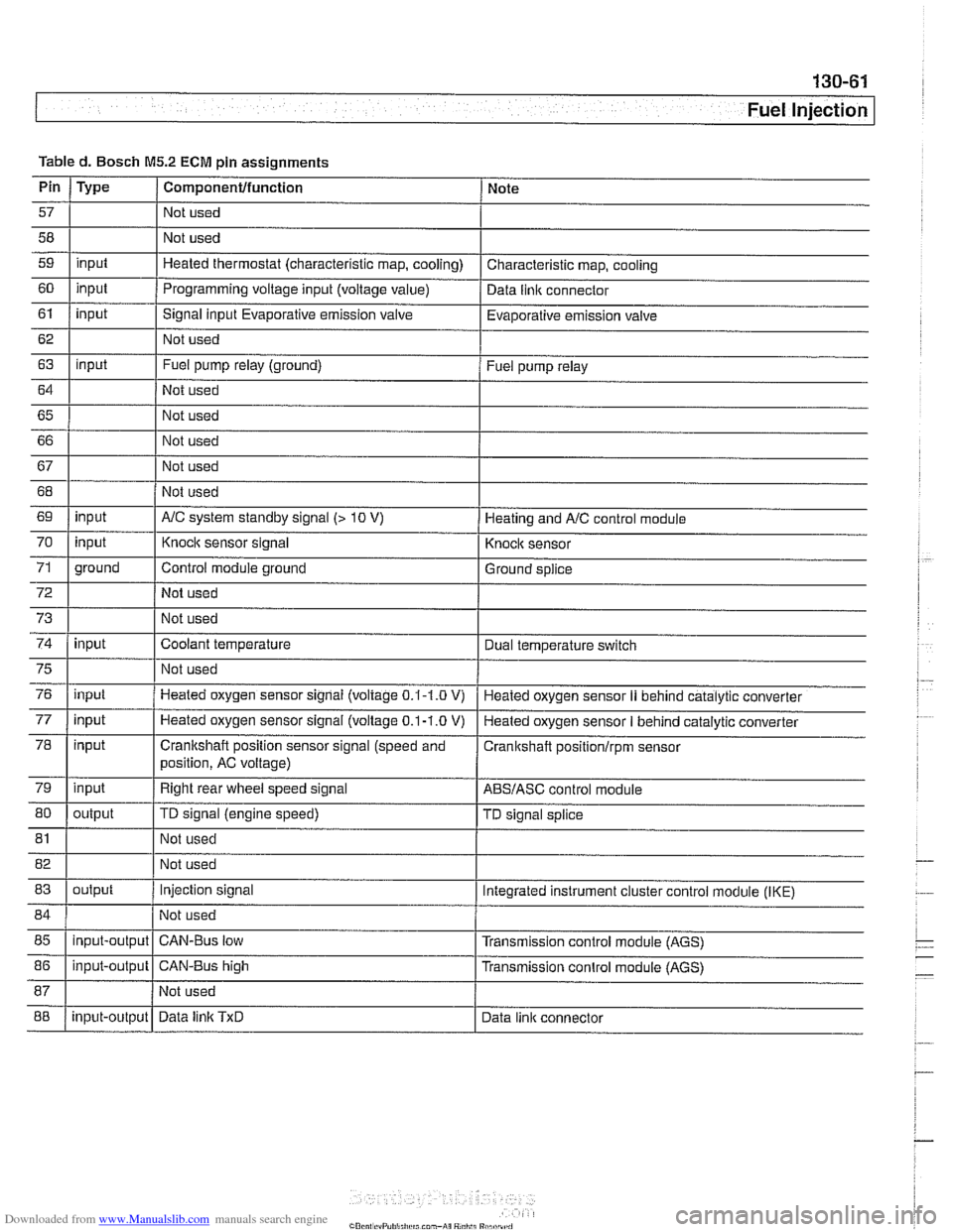
The Bosch M5.2 system used on 1997 540i models uses an
88-pin control unit. The
M5.2 system has the following func-
tions and capabilities:
Fully sequential cylinder-individual fuel injection.
Integrated adaptive knock control.
Oxygen sensor fuel mixture control.
0 Self-diagnosis and emergency operation characteristics.
CAN-Bus link.
0 OED II functions (misfire detection, catalytic converter
monitoring, oxygen sensor monitor, and fuel tank ventila-
tion system).
Electronic vehicle immobilization via EWS.
One-touch starter function.
Control of characteristic map thermostat.
M5.2.1 system features
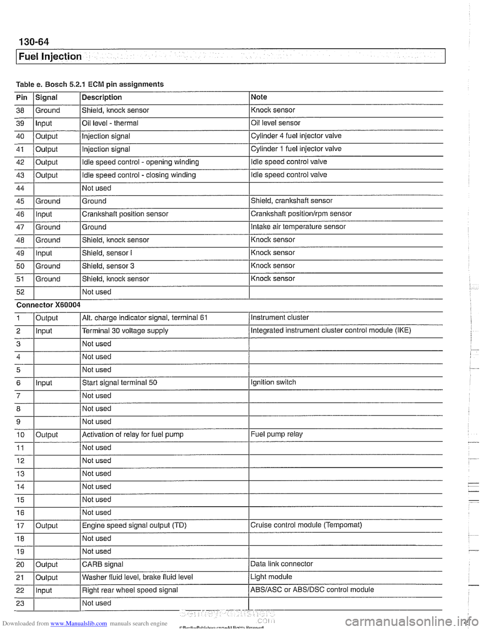
The Bosch M5.2.1 system is used on 1998 540i models. The
M5.2.1 control module utilizes the SKE (standard shell con-
struction housing) with 5 connectors and a combined total of
134 pins.
The M5.2.1 systefn has
tile following functions or capabilities:
Separate power supply relay for ignition coils. Leak diagnosis pump (LDP) control and feedback
rnonitor-
ing for evaporative system leak testing.
Fuel evaporative system providing ORVR (on-board refuel-
ing vapor recovery) compliancy.
Batterylalternator charge logic (idle speed varied with the
battery state of charge).
CAN-Bus communications with the instrument cluster
EWS
Ill "rolling code" ISN interface.
More sensitive ignition
knock sensors.
Pulse width modulated (P-W-M) Heating and
AIC (IHKA)
status signal.
Running loss (312-way) solenoid valve.
Page 448 of 1002
Downloaded from www.Manualslib.com manuals search engine
Fuel Injection Evaporative fuel system pressure leak
diagnosis, overview
(M5.2.1 only)
1998 540i models are equipped with an evaporative fuel sys-
tem pressure leak diagnosis system. The main component of
this system is the leak diagnosis pump (LDP). The function of
the LDP is to pressurize the fuel tank and the evaporative
emission system for the purpose of detecting
leaks. This sys-
tem is capable of detecting a leak as small as 0.5 mm.
The LDP, located in the left rear wheel housing, is a unitized
component that contains the following:
Vacuum chamber. Pneumatic pump chamber.
DME activated vacuum solenoid
Reed switch (provides switched voltage
feedback signal to
ECM).
The vacuum supply line is in the wiring harness from the en-
gine compartment and runs down the driver's side of the vehi-
cle.
The canister vent valve is integrated into the LDP, which is
electrically controlled by the ECM. The canister vent valve is
opened to provide fresh air entry into the fuel system only dur-
ing purge operation.
- Purge operation characteristics:
Off idle through full throttle: purge valve opened by pulse
width modulated (PWM) control of the ECM. PWM duty cy-
cle varies by engine operating conditions
(e.g. warm idle,
purge valve opened slightly; cold
idleldecel with engine
temp
< 67" C, purge valve always closed).
Page 451 of 1002
Downloaded from www.Manualslib.com manuals search engine
-. -
Fuel Injection
I 68 1 / Not used
Table
d. Bosch
M5.2 ECM pin assignments
I I I
69 1 input I AIC system standby signal (> 10 V) 1 Heating and AIC control module
Pin
57
58
59
60
61
62
63
64
65 66
67
Type
input
input
input
input
I 70
72
73
74
Componentlfunction
Not used
Not used
Heated thermostat (characteristic map, cooling)
Programming voltage input (voltage
value)
Signal input Evaporative emission valve
Not used
Fuel pump relay (ground)
Not used
Not used
Not used
Not used
75
76
77
78
79
80
Note
Characteristic map, cooling
Data
llnlc connector
Evaporative emission valve
Fuel pump relay
71 1 ground I Control module ground I Ground splice
input
input
81
input input
input
input
output Not used
I
Knock sensor signal
Not used
Not used
Coolant temperature
82 1 I Not used
83
I I
Knock sensor
Dual temperature
swltch
Not used
Heated oxygen sensor signal (voltage
0.1-1.0 V)
Heated oxygen sensor
signal (voltage 0.1-1.0 V)
Crankshaft position sensor signal (speed and
position, AC voltage)
Right rear wheel speed signal
TD signal (engine speed)
85
I I I
Heated oxygen sensor II behind catalytic converter
Heated oxygen sensor
I behind catalytic converter
Cranitshaft positionlrpm sensor
ABSIASC control module
TD signal splice
84 1 / Not used 1
output
88
86
1 input-output 1 CAN-Bus high I Transmission conlrol module (AGS)
input-output
Injection signal
input-output Integrated instrument cluster control
module (IKE)
CAN-Bus low Transmission control module (AGS)
Data
linlc TxD Data link connector
Page 454 of 1002
Downloaded from www.Manualslib.com manuals search engine
-
Fuel Injection
Table e. Bosch 5.2.1 ECM pin assignments
Pin
I~iqnal 1 Description 1 Note
I I I
46 llnput ICrankshaft position sensor Icrankshaft positionlrpm sensor
38
39
40
41
42
43
44
45 Ground Input
Output
Output
Output
Output
Ground
47
48
49
50
51
Not used
I Not used
52
Shield, knock sensor
Oil level
- thermal
Injection signal
injection signal
Idle speed control - opening winding
Idle speed control - closing winding
Not used
Ground
Ground
-- Ground Input
Ground
Ground Not used Knock sensor
Oil level sensor
Cylinder
4 fuel injector
valve
Cylinder
1 fuel injector valve
Idle speed control valve
Idle speed control valve
Shield, crankshaft sensor
5
6
7
12 Not used
Ground
Intake air temperature sensor
Connector
X60004
8
9 10
11
14 1 1 Not used I
Shield, knock sensor
Shield, sensor
I
Shield, sensor 3
Shield, itnock sensor
Input
- Knoclc sensor
Knock sensor
Knock sensor
Knock sensor
Instrument cluster
Output
2 llnput l~erminal 30 voltage supply /Megrated instrument cluster control module (IKE)
Alt. charge indicator signal, terminal 61 1
Not used
Start signal terminal
50
Not used
15
16
17
18
Output
Ignition switch
Not used
Not used
Activation of relay for fuel pump
Not used
19
Fuel pump relay
Output Not used
I I I 20 loutput ICARB signal /Data link connector
Not
used
Not used
Engine speed signal output (TD)
Not used
Light module
21
Cruise control module (Tempomat)
22 llnput I Right rear wheel speed signal /ABS/ASC or ABSIDSC control module
Oulput
Washer
fluid level,
brake fluid level