Ignition switch wiring BMW 528i 1998 E39 Workshop Manual
[x] Cancel search | Manufacturer: BMW, Model Year: 1998, Model line: 528i, Model: BMW 528i 1998 E39Pages: 1002
Page 3 of 1002

Downloaded from www.Manualslib.com manuals search engine
YOU are now in Volume I
I
Foreword ................... .. ........................................................................\
.......... v
Index
........................ .. ................................................................ rear of manual
General, 001 General Warnings and Cautions 002 Vehicle Identification and VIN Decoder
Maintenance OiO 020 Maintenance
Engine
100 Engine-General 110 Engine Removal and Installation
113 Cylinder Head Removal and
Installation
116 Cyiinder Head and Valvetrain 117 Camshaft Timing Chain
119 Lubrication System
200 Transmission-General
2 Transmission 210 clutch 230 ManualTransmission
I20 Ignition System
121 Battery, Starter, Alternator
130 Fuel Injection
160 Fuel Tank and Fuel Pump 170 Radiator and Cooling System
180 Exhaust System
240 Automatic Transmission
250 Gearshift Linkage 260 Driveshaft
Suspension, 300 Suspension, Steering and 330 Rear Suspension
Brakes-General 331 Final Drive
Steering and No Front Suspension 340 Brakes
320 Steering and Wheel Alignment
400 Body-General
410 Fenders, Engine Hood 411 Doors
412 Trunk Lid, Tailgate
510 Exterior Trim, Bumpers 512 Door Windows
Equipment 513 Interior Trim
7
Equipment and 720 seat Belts
Accessories 721 Airbag System (SRS)
OBD On-Board Diagnostics
. ............ ..
515 Central Lociting and
Anti-Theft
520 Seats 540 Sunroof
.................................................................... Foreword .............................. .. v
Index ................... .. ................................................................ rear of manual
Electrical
6 system
600 Electrical System-General 620 Instruments
610 Electrical Comoonent Locations 630 Liohts
611 wipers and washers 612 Switches eati in^ and Air Conditioning
Radio
. ........... ........ .........................
Electrical Wiring Diagrams
Page 71 of 1002
Downloaded from www.Manualslib.com manuals search engine
Two common causes of driveability problems are incorrect
system voltage and bad grounds.
System voltage
Digital motor electronics (DME) requires that the system (bat-
tery) voltage be maintained within a narrow range of DC volt-
age.
DC voltage levels beyond or below the operating range,
or any
AIC voltage in the electrical system can cause havoc.
When troubleshooting an illuminated MIL, make sure the bat-
tery is fully charged and capable of delivering all its power to
the electrical system. An undercharged battery can amplify
AIC alternator output ripple.
To
make a quick check of the battery charge, measure the
voltage across the battery terminals with all cables attached
and the ignition off.
Afully charged battery will measure 12.6
volts or slightly more, compared to 12.1 5 volts for a battery
with a 25% charge.
The DME system operates at low voltage and current levels,
making it sensitive to small increases in resistance. The elec-
trical system is routinely subjected to corrosion, vibration and
wear, so faults or corrosion in the wiring harness and connec-
tors are not uncommon. Check the battery terminals
forcorro-
sion or loose cable connections. See 121 Battery, Starter,
Alternator for additional information.
If a battery cable connection has no
v~sible faults but is still
suspect, measure the voltage drop across the connection. A
large drop indicates excessive resistance, meaning that the
connection is corroded, dirty, or damaged. Clean or repairthe
connection and retest.
NOTE-
For instructions on conducting a voltage drop test and other
general electrical troubleshooting information, see
600 Elec-
trical System-General.
Visually inspect all wiring, connectors, switches and fuses in
the system. Loose or damaged connectors can cause inter-
mittent problems, especially the small terminals in the ECM
connectors. Disconnect the wiring harness connectors to
check for corrosion, and use electrical cleaning spray to re-
move contaminants.
Main grounds
Good grounds are critical to proper DME operation. If a
ground connection has no visible faults but is still suspect.
measure the voltage drop across the connection. A large volt-
age drop means high resistance. Clean or repair the connec-
tion and retest.
LBuntr.yP~sbhnllcn.can#-AII A,~iltl Rcsrwsd
Page 216 of 1002
Downloaded from www.Manualslib.com manuals search engine
-. .
Cylinder Head and Valvetrain -- v . -- --- --
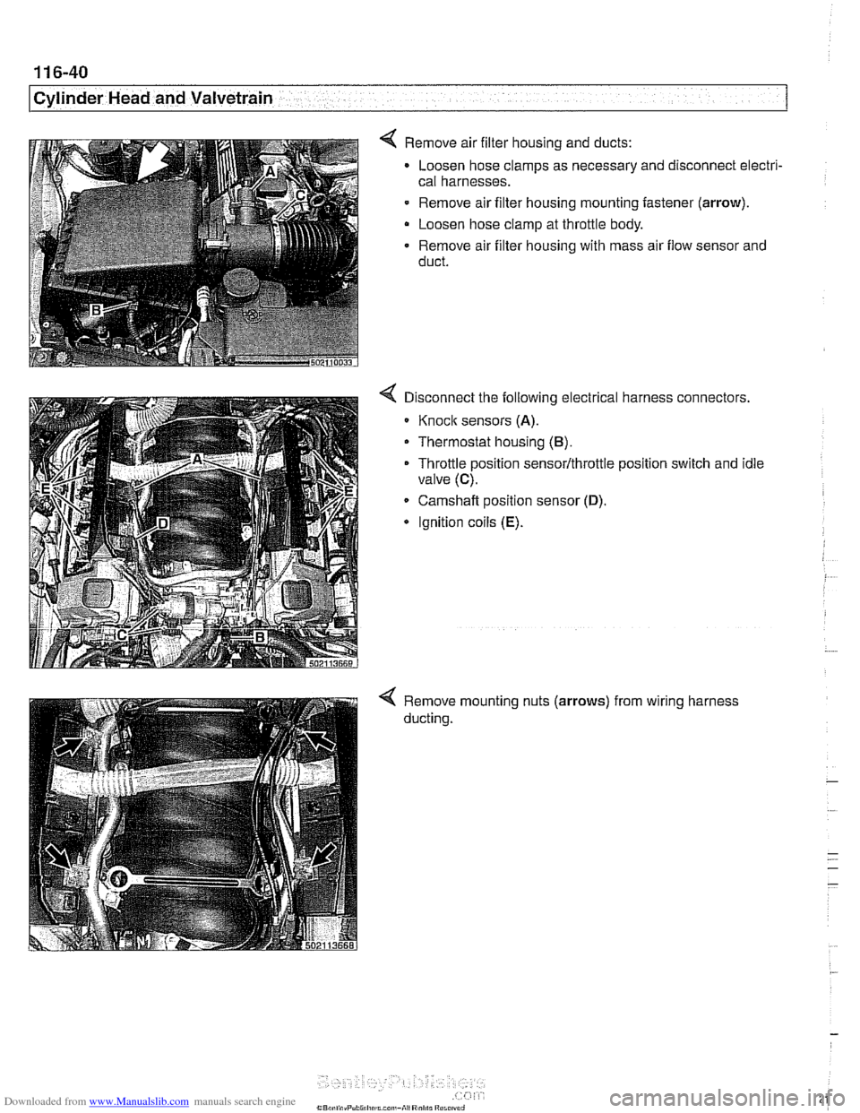
4 Remove air filter housing and ducts:
Loosen hose clamps as necessary and disconnect electri-
cal harnesses.
- Remove air filter housing mounting fastener (arrow).
Loosen hose clamp at throttle body.
Remove air filter housing with mass air flow sensor and
duct.
Disconnect the following electrical harness connectors.
Knoclc sensors (A).
Thermostat housing (B).
Throttle position sensor/throttle position switch and idle
valve
(C).
Camshaft position sensor (D).
* Ignition coils (E).
Remove mounting nuts (arrows)
ducting. from
wiring harness
Page 325 of 1002
Downloaded from www.Manualslib.com manuals search engine
. .- -
L
- --
- - -. - -- Lubrication ~~stern
- Remove pressure gauge and reinstall pressure switch with
new sealing washer.
Tightening torque
Oil pressure switch to oil filter housing 27 Nm (20 ft-lb)
If testing shows low oil pressure, one or more of the following
conditions may be indicated:
Worn or faulty oil pump or faulty pump pressure relief valve
Worn or damaged engine bearings
Severe engine wear
Any of these conditions indicate the need for major repairs.
Oil pressure warning system, testing
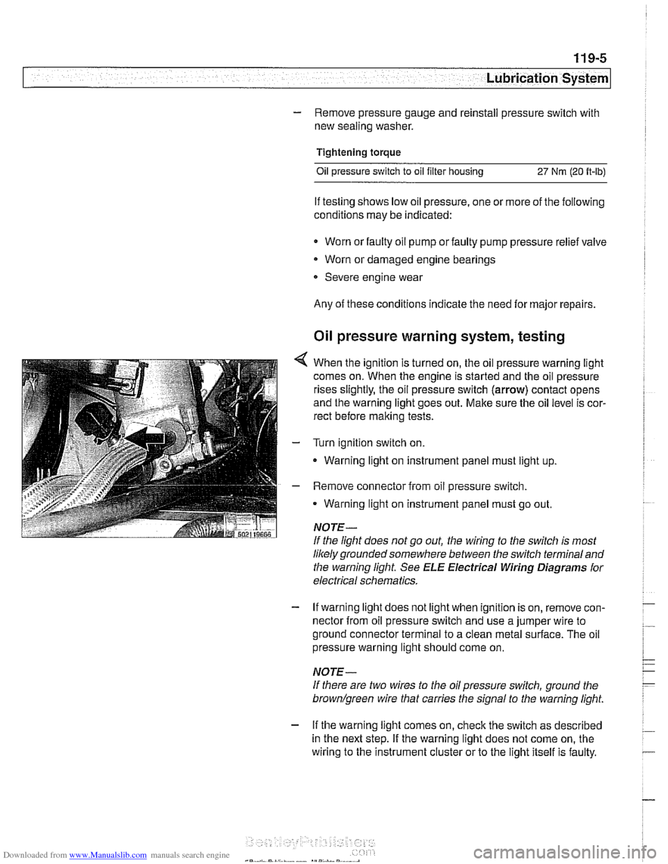
4 When the ignition is turned on, the oil pressure warning light
comes on. When the engine is started and the oil pressure
rises slightly, the oil pressure switch (arrow) contact opens
and the warning light goes out. Make sure the oil level is cor-
rect before making tests.
- Turn ignition switch on.
- Warning light on instrument panel must light up
- Remove connector from oil pressure switch.
Warning light on instrument panel must go out.
NOTE-
If the light does not go out, the wiring to the switch is most
likely grounded somewhere between the switch terminaland
the warning light See
ELE Electrical Wiring Diagrams for
electrical schematics.
- If warning light does not light when ignition is on, remove con-
nector from oil pressure switch and use a jumper wire to
ground connector terminal to a clean metal surface. The oil
pressure warning light should come on.
NOTE-
If there are two wires to the oil pressure switch, ground the
brown/green wire that carries the signal to the warning light.
- If the warning light comes on, check the switch as described
in the next step. If the warning light does not come on, the
wiring to the instrument cluster or to the light itself is faulty.
Page 351 of 1002
Downloaded from www.Manualslib.com manuals search engine
120-3
Ignition System
Warnings and cautions
The ignition system produces dangerous high voltage. In ad-
dition the sensitive electronic components can be damaged
if
proper precautions are not adhered to.
WARNING-
* Do not touch or disconnect any cables from the coils while
the engine is running or being
cranked by the starter.
The ignition system produces high voltages that can be
fatal. Avoid contact with exposed terminals. Use ex-
treme caution when working on a car with the ignition
switched on or the engine running.
- Connect and disconnect tlie DME system wiring and
test equipment leads only when the ignition is
OFF:
Before operating the starter without starting the engine
(for example when
making a compression test) always
disable the ignition.
CA
U TIOW-
Do not attempt to disable the ignition by removing the coils
from the spark plugs.
Connect or disconnect ignition system wires, multiple
wire connectors, and ignition test equipment leads only
while the ignition is
off Switch multimeter functions or
measurement ranges only with the test probes discon-
nected.
* Do not disconnect the battery while the engine is run-
ning.
A high impedance digital multimeter should be used for
all voltage and resistance tests. An LED test light
should be used in place of an incandescent-type test
lamp.
In general, make test connections only as specified by
BMW as described in this manual, or as described by
the instrument manufacturer.
Engine management
BMW €39 engines use an advanced engine management
system known as Digital Motor Electronics (DME). DME in-
corporates on-board diagnostics, fuel injection, ignition and
other engine control functions. DME variants are listed in
Table a. Engine management systems.
Second generation On-Board Diagnostics
(OED II) is incor-
porated into the engine management systems used on the
cars covered by this manual. Use a BMW-specific electronic
scan tool, or a "Generic"
OED II scan tool to access Diagnos-
tic Trouble Codes (DTCs). DTCs can help pinpoint ignition
ine management problems.
Page 353 of 1002
Downloaded from www.Manualslib.com manuals search engine
Lnition switch
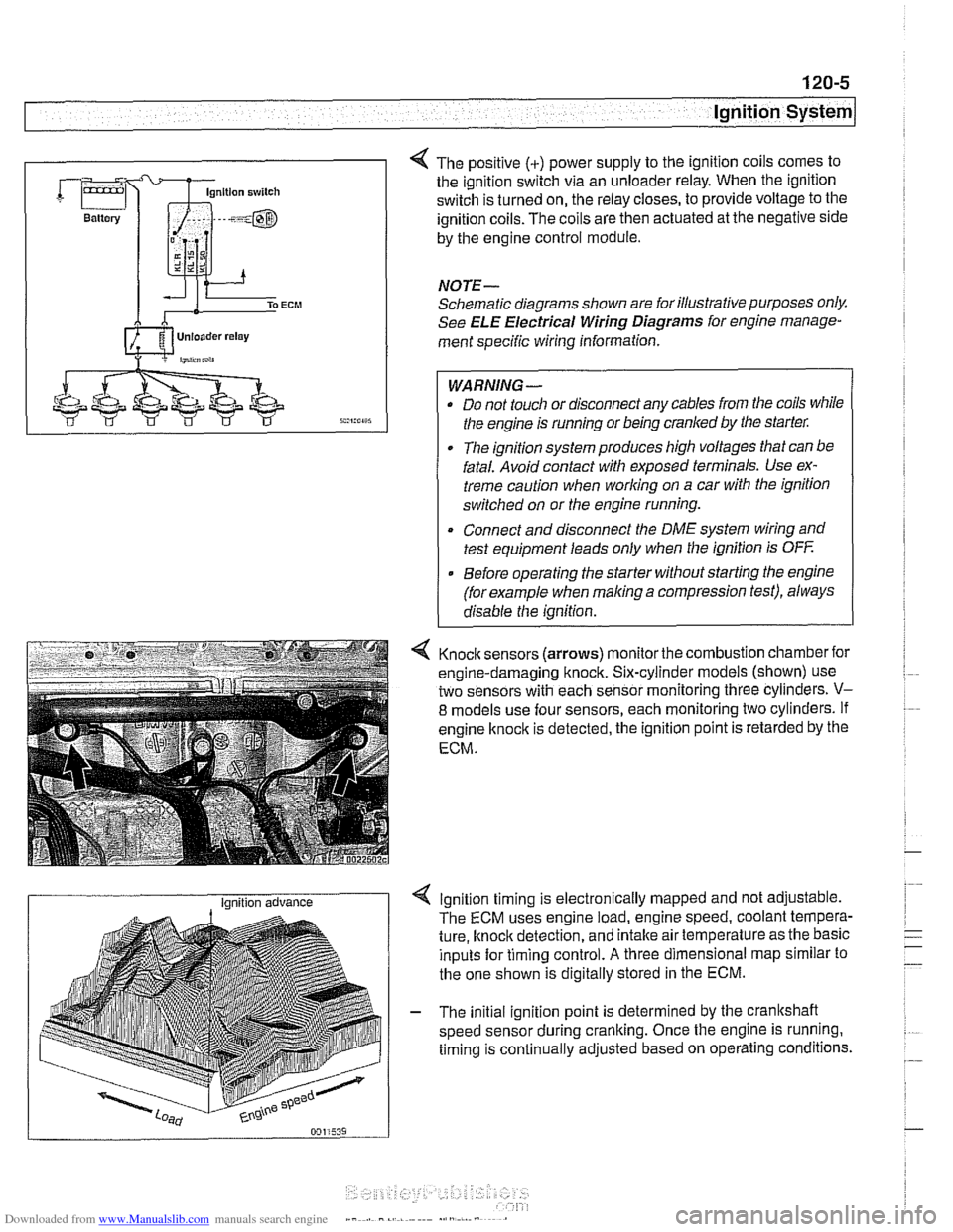
4 The positive (+) power supply to the ignition coils comes to
the ignition switch via an unloader relay. When the ignition
switch is turned on, the relay closes, to provide voltage to the
ignition coils. The coils are then actuated at the negative side
by the engine control module.
NOTE-
Schematic diagrams shown are for illustrative purposes only.
See ELE Electrical Wiring Diagrams for engine manage-
ment specific wiring information.
WARNING- Do not touch or disconnect any cables from the coils while
the engine is running or being cranked by the starter:
The ignition system produces high voltages that can be
fatal. Avoid contact with exposed terminals. Use ex-
treme caution when
working on a car with the ignition
switched on or the engine running.
* Connect and disconnect the DME system wiring and
test equipment leads only when the ignition is
OFF
Before operating the starter without starting the engine
(for example when
making a compression test), always
disable the ignition.
4 Knock sensors (arrows) monitor the combustion chamber for
engine-damaging knock. Six-cylinder models (shown) use
two sensors with each sensor monitoring three cylinders.
V-
8 models use four sensors, each monitoring two cylinders. If
engine
knock is detected, the ignition point is retarded by the
ECM.
I Ignition advance Ignition timing is electronically mapped and not adjustable.
The ECM uses engine load, engine speed, coolant tempera-
ture, knock detection, and intake air temperature as the basic
inputs for timing control.
A three dimensional map similar to
the one shown is digitally stored in the ECM.
- The initial ignition point is determined by the crankshaft
speed sensor during cranking. Once the engine is running.
timing is continually adjusted based on operating conditions.
Page 385 of 1002
Downloaded from www.Manualslib.com manuals search engine
Battery, Starter, Alternator
- Installation is reverse of removal, noting the following:
Replace alternator rubber sealing O-ring.
* Fill and bleed cooling system as described in 170 Radiator
and Cooling System.
Tightening torques
Fan clutch to coolant pump
with
BMW special tool 11 5 040 30 Nm (22 ft-lb)
without
BMW special tool 11 5 040 40 Nm (29 ft-lb)
Terminal 30 (Bc) wire to alternator (ME) 13 Nm (10 ft-lb)
STARTER
Starter troubleshooting
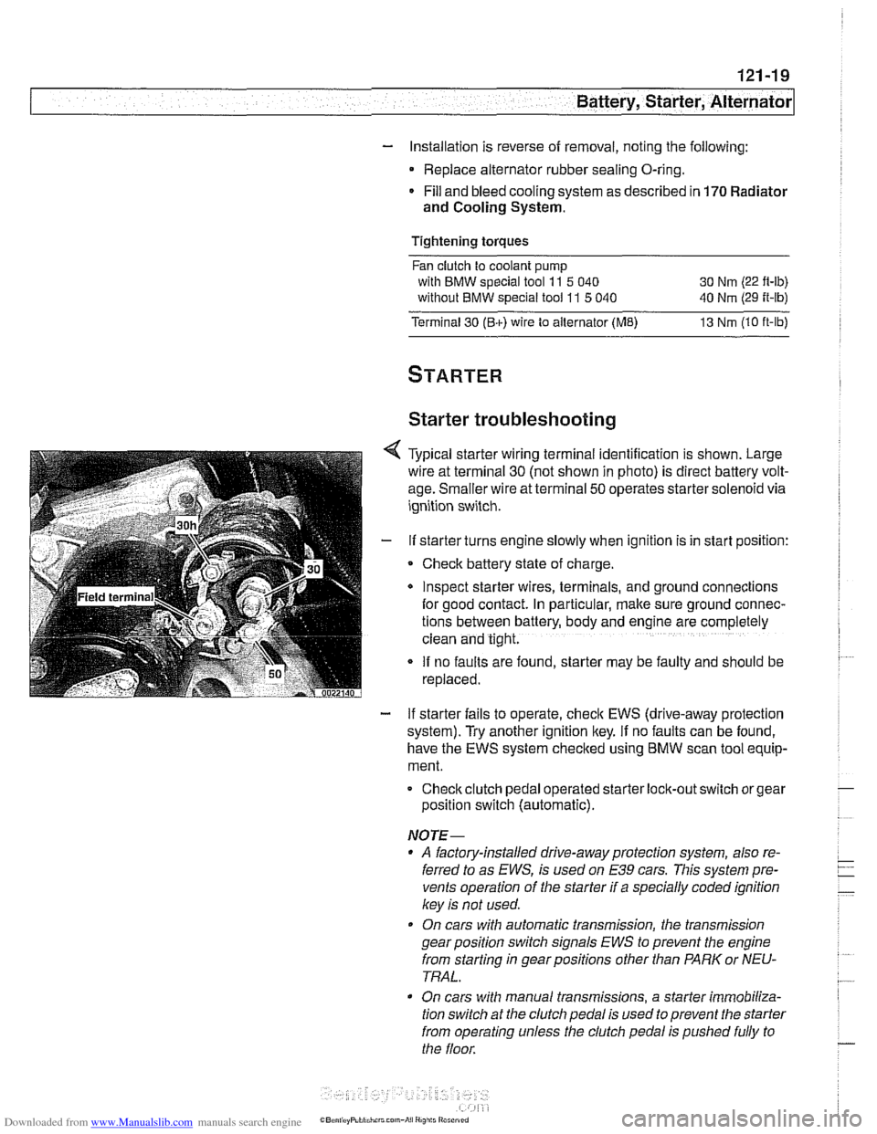
Typical starter wiring terminal identification is shown. Large
wire at terminal
30 (not shown in photo) is direct battery volt-
age. Smaller wire at terminal
50 operates starter solenoid via
ignition switch.
If starter turns engine slowly when ignition is in start position:
Check battery state of charge.
Inspect starter wires, terminals, and ground
connectlons
for good contact. In particular, make sure ground connec-
tions between battery, body and
englne are completely
clean and tight.
If no faults are found, starter may be faulty and should be
replaced.
- If starter fails to operate, check EWS (drive-away protection
system). Try another ignition key.
If no faults can be found,
have the EWS system checked using
BMW scan tool equip-
ment.
Checkclutch pedal operated
starter lock-out switch or gear
position switch (automatic).
NOTE-
* A factory-installed drive-away protection system, also re-
ferred to as
EWS, is used on E39 cars. This system pre-
vents operation of the starter if a specially coded ignition
key is not used.
On cars with automatic transmission, the transmission
gear position switch signals
EWS to prevent the engine
from starting in gear positions other than PARK or NEU-
TRAL.
On cars with manual transmissions, a starter immobiliza-
tion switch
at the clutch pedal is used to prevent the starter
from operating unless the clutch pedal is pushed fully to
the floor.
Page 386 of 1002
Downloaded from www.Manualslib.com manuals search engine
I Battery, Starter, Alternator
- Check for battery voltage at terminal 50 of starter motor with
key in start position. If voltage is not present, check wiring be-
tween ignition switch and starter terminal. Check the EWS
system and other inputs that disrupt terminal
56 to the start-
er. See ELE Electrical
Wiring Diagrams. If voltage is
present and no other visible wiring faults can be found, prob-
lem is most likely in starter motor.
Starter, removing and installing
(6-cylinder engine)
The starter is removed from below. Access to starter bolts is
difficult. Be sure to have the proper tools on hand before pro-
ceeding.
NOTE-
Access to the starter wiring is very limited. Forbetteraccess,
it may be necessary to remove the intake manifold.
- Disconnect negative (-) battery cable.
CAUTIOI\C
Prior to disconnecting the battern read the baltery discon-
nection cautions
in OOlGeneral Cautions and Warnings.
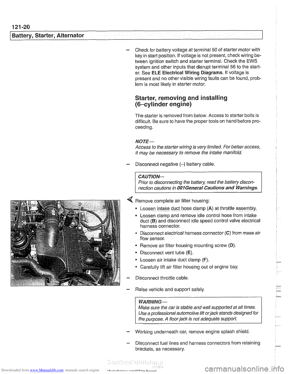
Remove complete air filter hous~ng:
Loosen intake duct hose clamp (A) at throttle assembly.
Loosen clamp and remove idle control hose from intake
duct
(B) and disconnect idle speed control valve electrical
harness connector.
Disconnect electrical harness connector
(C) from mass air
flow sensor.
Remove air filter housing mounting screw (D)
Disconnect vent tube
(E).
Loosen air intake duct clamp (F).
Carefully lift air filter housing out of engine bay.
Disconnect throttle cable.
Raise vehicle and support safely.
WARNING-
Make sure the car is stable and well supported at all times.
Use a professional automotive
lift orjack stands designed for
the purpose. A
floorjaclc is not adequate support
- Working underneath car, remove engine splash shield
- Disconnect fuel lines and harness connectors from retaining
brackets, as necessary.
Page 395 of 1002
Downloaded from www.Manualslib.com manuals search engine
Fuel Injection
Warnings and cautions
For personal safety, as well as the protection of sensitive
electronic components, adhere to the warnings and cautions
on the following pages.
WARNING-
Gasoline is highly flammable and its vapors are explosive.
Do not smoke or work on a car near heaters or other fire
hazards when diagnosing and repairing fuel system prob-
lems. Have a fire extinguisher available in case of an emer-
gency
Renew fuel system hoses, clamps and O-rings any
time they are removed.
When working on an open fuel system, wear suitable
hand protection, as prolonged contact
with fuel can
cause illnesses and skin disorders.
* The ignition system produces high voltages that can be
fatal. Avoid contact with exposed terminals. Use ex-
treme caution when
working on a car with the ignition
switched on or the engine running.
CAUTION-
- Disconnecting the battery may erase fault code($ storedin
memory Check for fault codes prior to disconnecting the
battery cables. Read the battery disconnection cautions in
001 General Warnings and Cautions.
a Connect and disconnect the DME system wiring and
1 test equipment leads only when the ignition is switched
off.
Wait at least 1 minute after turning off the ignition be-
fore removing the engine control module (ECM) con-
nector. If the connector is removed before this time,
residualpower in the system relay may damage the
control module.
Fuel system cleaners and other chemical additives oth-
er than those specifically recommended by BMW may
damage the catalytic converter, the oxygen sensor or
other fuel supply components.
* Do not connect any test equipment that delivers a 12-
volt power supply to terminal 15 (+) of the ignition coil.
The current flow may damage the ECM. In general,
connect test equipment only as specified by BMW or
the equipment maker.
Only use a digital
multirneter for electrical tests. Only
use an LED test light for
quiclc tests.
Page 442 of 1002
Downloaded from www.Manualslib.com manuals search engine
.. .-
/Fuel lnjeciion
NOJE-
With engine oft disconnect harness connector and checlc
heating element resistance between white wires on the sen-
sor side of harness. If the element is electrically open (no
continuity), replace sensor.
- If oxygen sensor does not produce a fluctuating voltage and
preheater circuit is
OK, replace sensor.
NOJE-
If not already applied, coat oxygen sensor threads w~th anti-
seize compound before installat~on. Do not get the com-
pound on the sensor tip.
Tightening torque Oxygen sensor to exhaust system
55 Nm (41 ft-lb)
Fuel injectors, checking and replacing
The fuel iniectors are switched on and off (oaened and
closed)
by'the ECM. The injectors are connkcted to acom-
mon power source. A ground signal from the ECM is used to
open and close the injectors.
CA U JIOG
Use only a digital multimeter or an LED injector tester when
testing injectors or wiring. Use of an analog
VOM or incan-
descent test light may damaqe the engine controlmodule.
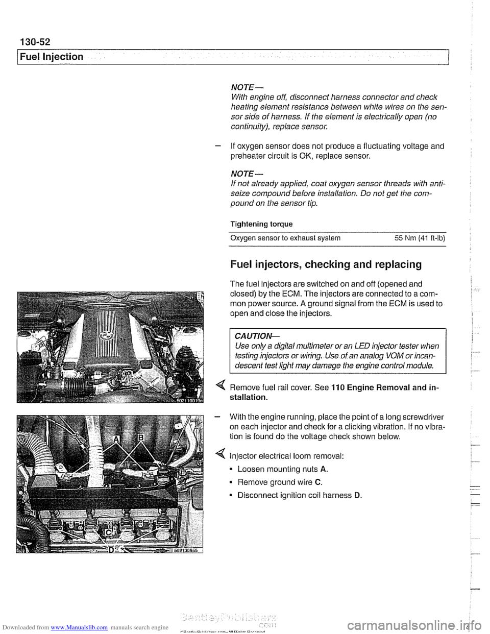
4 Remove fuel rail cover. See 110 Engine Removal and in-
stallation.
With the engine running, place the point of a long screwdriver
on each injector and check for a cliclting vibration.
If no vibra-
tion is found do the voltage
checit shown below.
Injector electrical loom removal:
- Loosen mounting nuts A.
Remove ground wire C.
Disconnect ignition coil harness D