Vanos solenoid BMW 528i 1998 E39 Workshop Manual
[x] Cancel search | Manufacturer: BMW, Model Year: 1998, Model line: 528i, Model: BMW 528i 1998 E39Pages: 1002
Page 77 of 1002
Downloaded from www.Manualslib.com manuals search engine
Engine Removal and lnstallationl
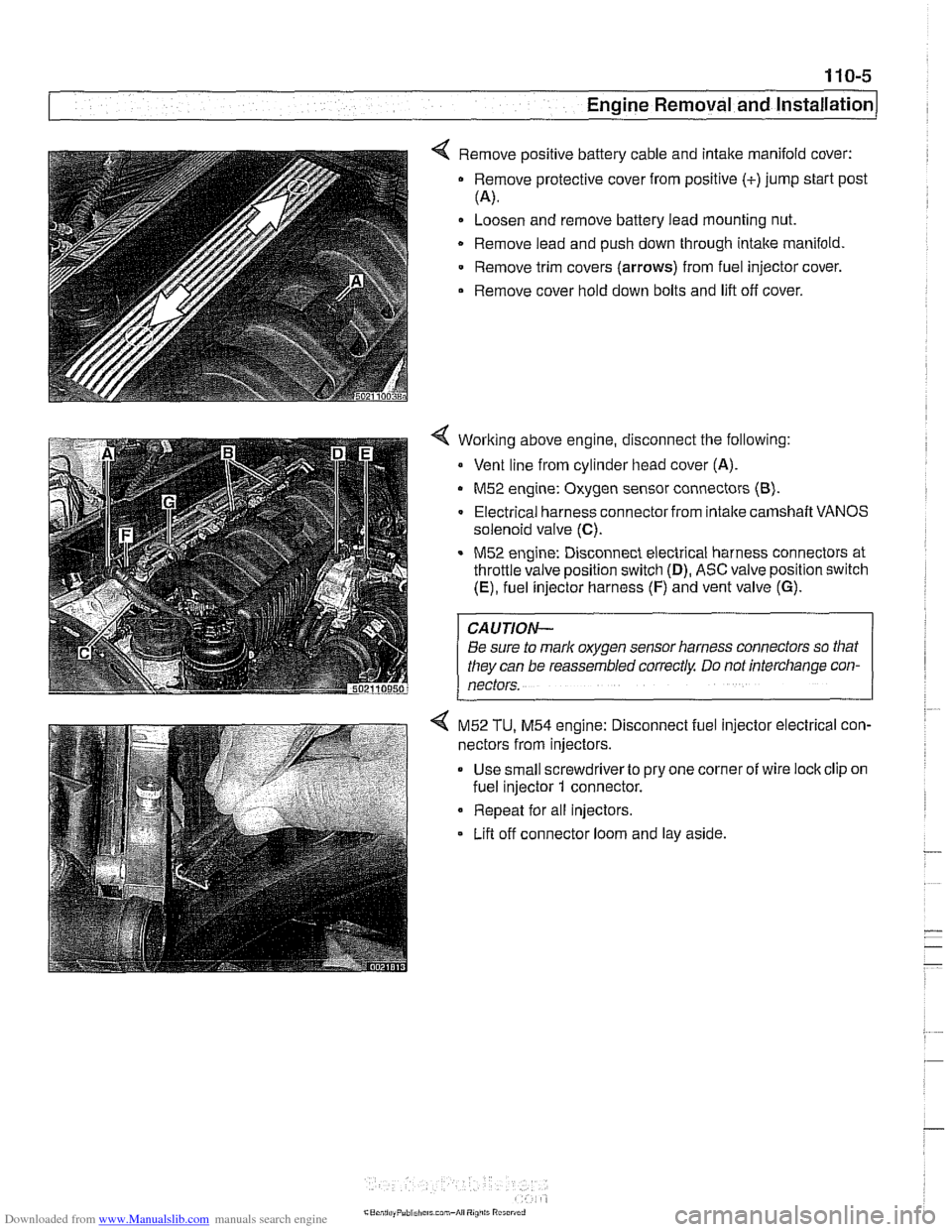
< Remove positive battery cable and intake manifold cover:
Remove protective cover from positive (+)jump start post
(4.
Loosen and remove battery lead mounting nut.
Remove lead and push down through intake manifold
Remove trim covers
(arrows) from fuel injector cover.
Remove cover hold down bolts and lift off cover.
Working above engine, disconnect the following:
Vent line from cylinder head cover (A).
M52 engine: Oxygen sensor connectors (8).
Electrical harness connector from intalte camshaft VANOS
solenoid valve
(C).
M52 engine: Disconnect electrical harness connectors at
throttle valve position switch
(D), ASC valve position switch
(E), fuel injector harness (F) and vent valve (G).
CAUTION-
Be sure to mark oxygen sensor harness connectors so that
they can be reassembled correctly Do not interchange con-
nectors.
4 M52 TU, M54 engine: Disconnect fuel injector electrical con-
nectors from injectors.
Use small screwdriverto pry one corner of wire lock clip on
fuel injector
1 connector.
Repeat for all injectors.
Lifl off connector loom and lay aside.
Page 104 of 1002
Downloaded from www.Manualslib.com manuals search engine
113-10
Cylinder Head Removal and Installation
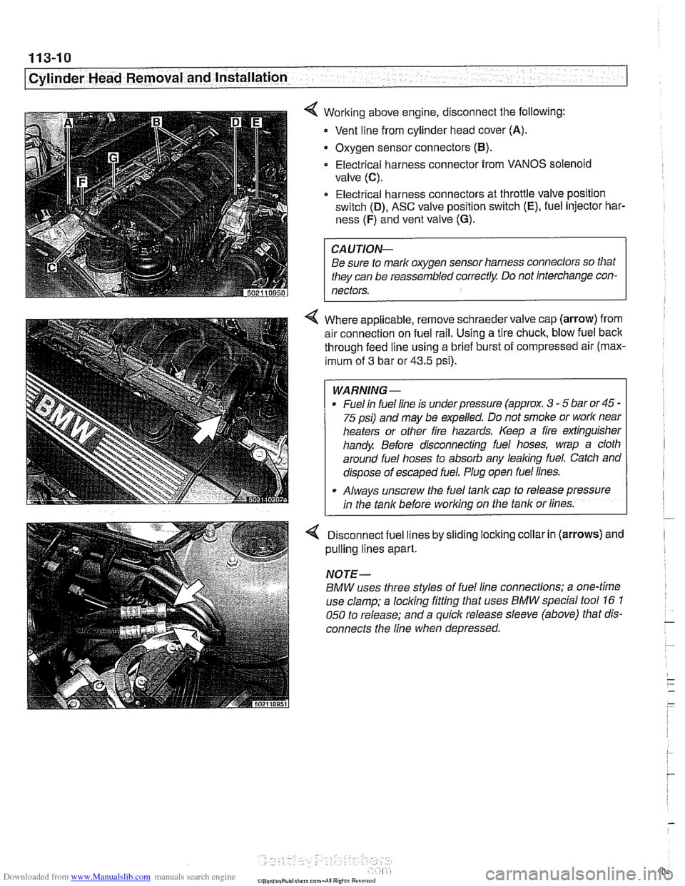
4 Working above engine, disconnect the following:
Vent line from cylinder head cover
(A).
. Oxygen sensor connectors (B).
Electrical harness connector from VANOS solenoid
valve
(C).
Electrical harness connectors at throttle valve position
switch
(D), ASC valve position switch (E), fuel injector har-
ness
(F) and vent valve (G).
CAUTION-
Be sure to mark oxygen sensor harness connectors so that
they can be reassembled correctly Do not interchange con-
nectors.
4 Where applicable, remove schraeder valve cap (arrow) from
air connection on fuel rail. Using a tire chuck, blow fuel back
through feed line using a brief burst of compressed air (max-
imum of
3 bar or 43.5 psi).
WARNING-
. Fuel in fuel line is underpressure (approx. 3 - 5 bar or 45 -
75 psi) and may be expelled. Do not smoke or work near
heaters or other fire hazards. Keep a fire extinguisher
handy Before disconnecting fuel hoses, wrap a cloth
around fuel hoses to absorb any leaking fuel. Catch and
dispose of escaped fuel. Plug open fuel lines.
- Always unscrew the fuel rank cap ro release pressure
;n the tank before working on the tank or lines.
Disconnect fuel lines by sliding locking collar in (arrows) and
pulling lines apart.
NOTE-
BMW uses three styles of fuel line connections; a one-time
use
clamp; a locking fitting that uses BMWspecial tool 16 1
050 to release; and a quick release sleeve (above) that dis-
connects the line when depressed.
Page 115 of 1002
Downloaded from www.Manualslib.com manuals search engine
- -.
Cylinder Head Removal and lnstallation
NOTE-
Be Sure the secondary timing chain tensioner is locked down
and the exhaust
camshaif mounting bolts are loose before
proceeding.
- Install VANOS control unit. See VANOS control unit, install-
ing
(M52 engine) in 117 Camshaft Timing Chain.
CAUTION--
Incorrect installation ofthe VANOS control may result in dam-
age to the engine valvefrain.
- Install exhaust manifolds using new gaskets and nuts. Coat
manifold studs with copper paste prior to installing nuts.
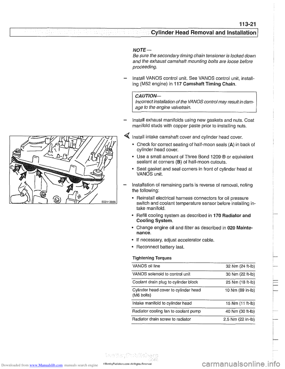
Install intake camshaft cover and cylinder
head cover.
Check for correct seating of half-moon seals
(A) in back of
cylinder head cover.
Use a small amount of Three Bond 1209
O or equivalent
sealant at corners
(6) of half-moon cutouts.
Seat gasket and seal corners in front of cylinder head at
VANOS unit.
- Installation of remaining parts is reverse of removal, noting
the following:
Reinstall electrical harness connectors for oil pressure
switch and coolant temperature sensor before installing in-
take manifold.
Refill cooling system as described in 170 Radiator and
Cooling System.
Change engine oil and filter as described in 020 Mainte-
nance.
If necessary, adjust accelerator cable.
Reconnect battery last.
Tightening Torques
VANOS oil line
32 Nm (24
ft-lb)
VANOS solenoid to control unit 30 Nm (22 ft-lb)
Coolant drain plug to cylinder
block 25 Nm (18 ft-lb)
Cylinder head cover to cylinder head
10 Nrn (89 in-lb)
(M6 bolts)
intake manifold to cylinder head 15 Nm (I 1 ft-lb)
Radiator cooling fan to coolant pump
40 Nm (30 ft-lb) - . .
Radiator drain screw to radiator 2.5 Nm (22 in-lbl
Page 117 of 1002
Downloaded from www.Manualslib.com manuals search engine
- --
Cylinder Head Removal and Installation 1 --
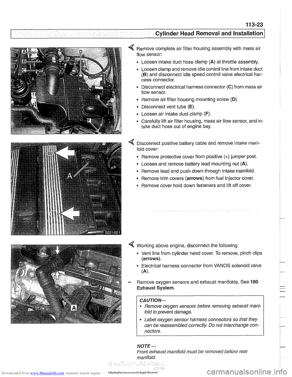
< Remove complete air filter housing assembly with mass air
flow sensor:
Loosen
intalte duct hose clamp (A) at throttle assembly.
Loosen clamp and remove idle control line from intake duct
(B) and disconnect idle speed control valve electrical har-
ness connector.
Disconnect electrical harness connector
(C) from mass air
flow sensor.
Remove air filter housing mounting screw
(D).
Disconnect vent tube (E).
. Loosen air intalte duct clamp (F).
Carefully lifl air filter housing, mass air flow sensor, and in-
take duct hose out of engine bay.
4 Disconnect positive battery cable and remove intake rnani-
fold cover:
Remove protective cover from positive (+)jumper post.
Loosen and remove battery lead mounting nut (A).
Remove lead and push down through intake manifold.
* Remove trim covers (arrows) from fuel injector cover.
Remove cover hold down fasteners and lifl off cover.
4 Worlting above engine, disconnect the following:
Vent line from cylinder head cover. To remove, pinch clips
(arrows).
Electrical harness connector from VANOS solenoid valve
(A).
- Remove oxygen sensors and exhaust manifolds. See 180
Exhaust System.
CAUTION-
Remove oxygen sensors before removing exhaust mani-
fold to prevent damage.
Label oxygen sensor harness connectors so that they
can be reassembled correctly Do not interchange con-
nectors.
NOTE-
Front exhaust manifold must be removed before rear
manifold.
Page 147 of 1002
Downloaded from www.Manualslib.com manuals search engine
Cylinder Head Removal and Installation /
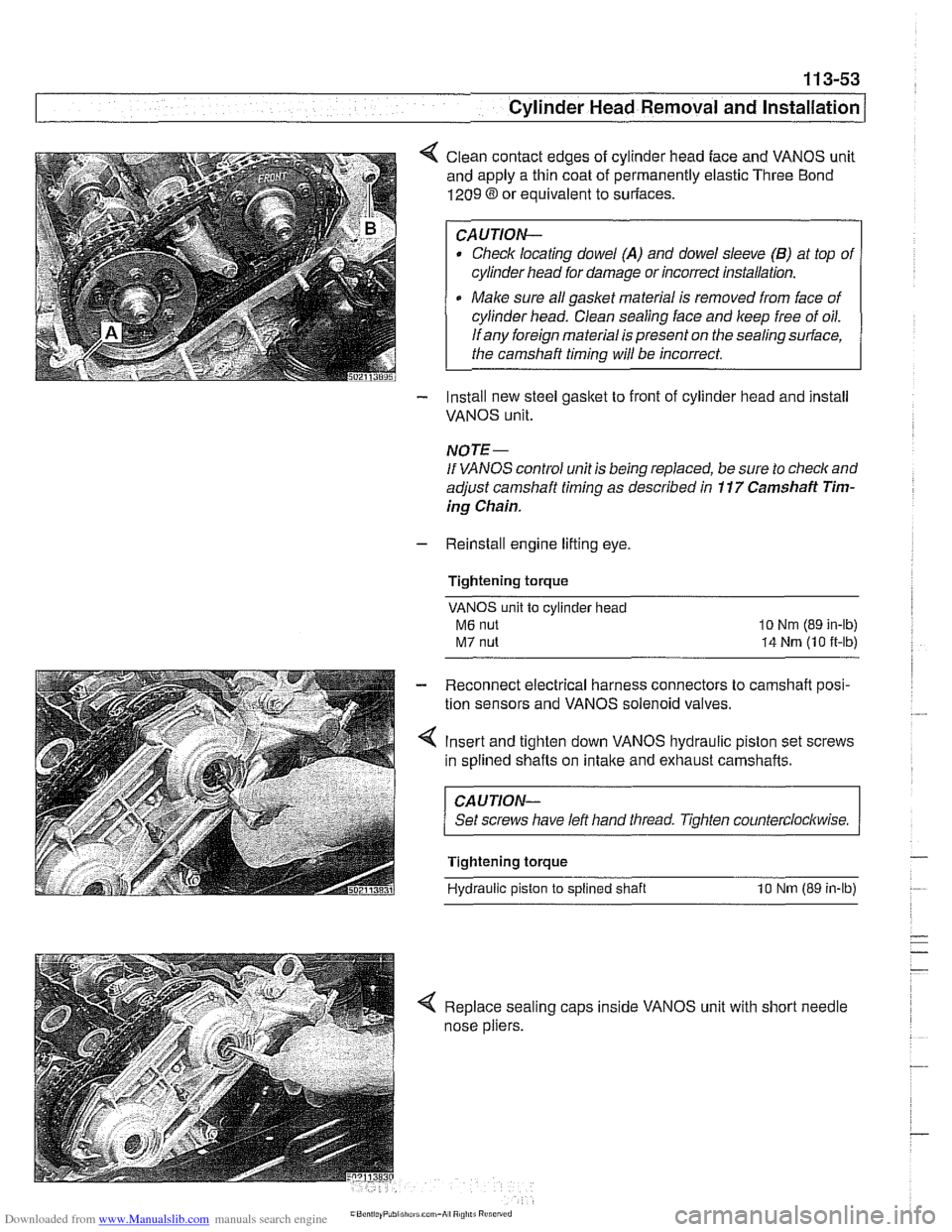
< Clean contact edges of cylinder head face and VANOS unit
and apply a thin coat of permanently elastic Three Bond
1209 8 or equivalent to suriaces.
CAUTION-
Check locating dowel (A) and dowel sleeve (B) at top of
cylinder head for damage or incorrect installation.
Make sure all gasket material is removed from face of
cylinder head. Clean sealing face and keep free of oil.
If any foreign material is present on the sealing surface,
the camshaft timing will be incorrect.
- Install new steel gasket to front of cylinder head and install
VANOS unit.
NOTE -
If VANOS control unit is being replaced, be sure to check and
adjust camshaft timing as described in
11 7 Camshaft Tim-
ing Chain.
- Reinstall engine lifting eye.
Tightening torque
VANOS unit to cylinder head
M6 nut
M7 nut
lo Nm (89 in-lb)
14 Nrn (10 it-lb)
- Reconnect electrical harness connectors to camshaft posi-
tion sensors and VANOS solenoid valves.
4 Insert and tighten down VANOS hydraulic piston set screws
in splined shafts on
intake and exhaust camshafts.
CAUJION-
Set screws have left hand tliread. Tighten counterclockwise.
Tightening torque
Hydraulic piston
to splined shaft 10 Nm (89 in-lb)
< Replace sealing caps inside VANOS unit with short needle
nose pliers.
Page 213 of 1002
![BMW 528i 1998 E39 Workshop Manual Downloaded from www.Manualslib.com manuals search engine
-
. - - -- Cylinder Head and valvetrain]
Turn engine over twice in direction of rotation until cylinder 1
intake and exhaust camshaft BMW 528i 1998 E39 Workshop Manual Downloaded from www.Manualslib.com manuals search engine
-
. - - -- Cylinder Head and valvetrain]
Turn engine over twice in direction of rotation until cylinder 1
intake and exhaust camshaft](/img/1/2822/w960_2822-212.png)
Downloaded from www.Manualslib.com manuals search engine
-
. - - -- Cylinder Head and valvetrain]
Turn engine over twice in direction of rotation until cylinder 1
intake and exhaust camshaft lobes (arrows) face each other.
- Lock crankshaft in TDC position with BMW special tool
11 2 300.
4 Place BMW special tool set 11 3 240 over camshafts and
measure clearances.
NOTE-
@ If the exhaust side of the tool (A) is not flush with the head,
camshaft timing is incorrect. Reset camshaft timing as de-
scribed in 11
7 Camshaft Timing Chain.
Due to flexible sprocket design, VANOS unit tolerances
and play in the VANOS splines, when the camshaft timing
is set correctly, the intake side of special tool set
11 3 240
(B) may be up to 1 mm (0.04 in.) above the suiface of the
cylinder head. This is normal. Reassemble engine. Other-
wise, reset camshaft timing as describedin 1
l?Camshaft
Timing Chain.
- Remove BMW special tool 11 6 150 from front of cylinder
head.
4 Clean contact edges of cylinder head face and VANOS unit
and apply a thin coat of Three Bond
12090 or equivalent
sealing compound to surfaces.
CAUTION-
Male sure all gasket material is removed from face of cyl-
inder head. Clean sealing face and keep free of oil.
Check locating dowel
(A) and dowel sleeve (B) at top
of cylinder head for damage or incorrect installation.
- Using a new steel gasket, install VANOS unit to front of cyi-
inder head. See 117 Camshaft Timing Chain.
NOTE-
If VANOS control unit is being replaced, be sure to check and
adjust camshaft timing as described in 117 Camshaft Tim-
ing Chain.
- Reinstall engine lifting eye.
- Reconnect electrical harness connectors to camshaft posi-
tion sensors and
VANOS solenoid valves.
Page 260 of 1002
Downloaded from www.Manualslib.com manuals search engine
1 17-24
I Camshaft Timing Chain
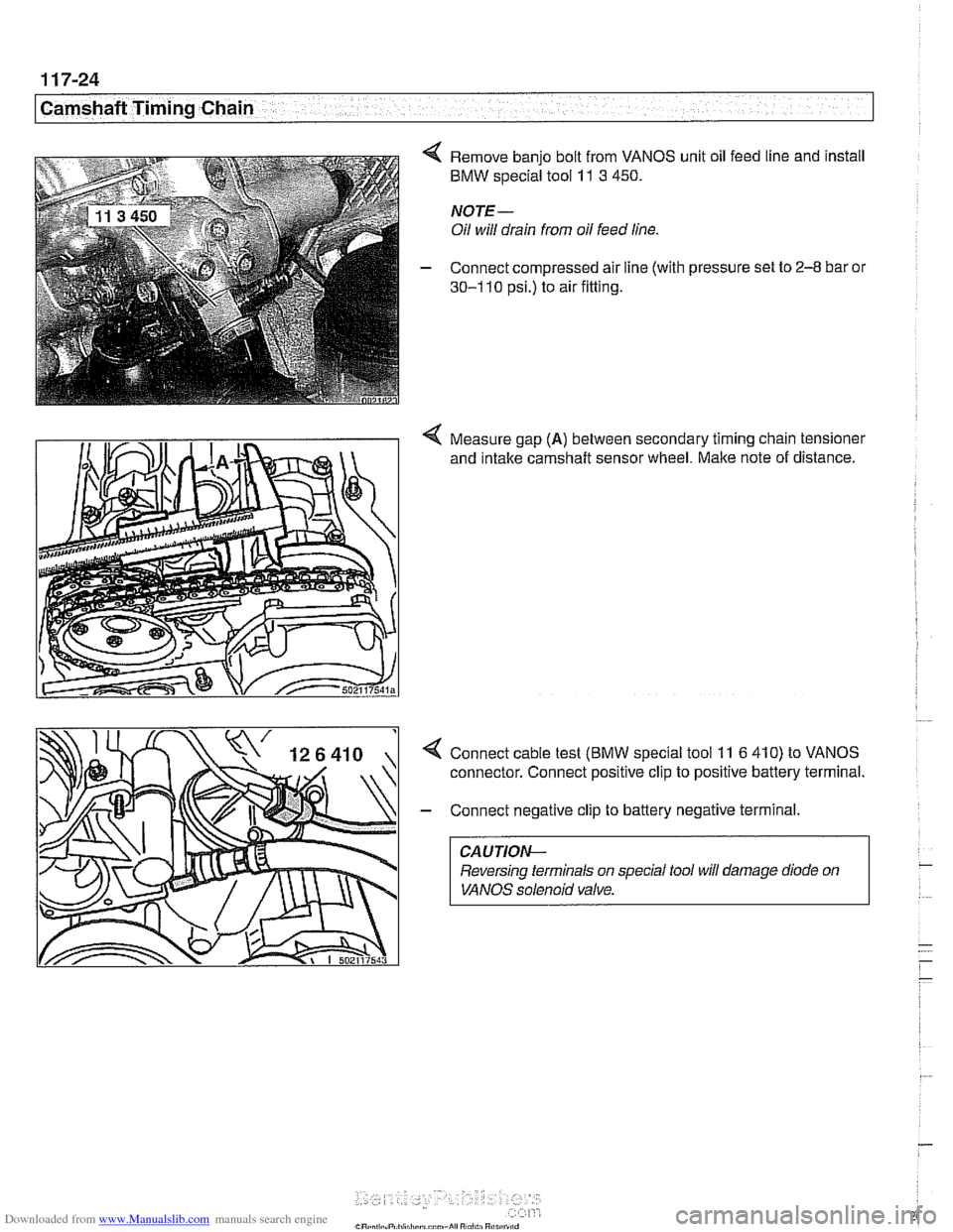
4 Remove banjo bolt from VANOS unit oil feed line and install
BMW special tool 11 3 450.
NOTE-
Oil will drain from oil feed line.
- Connect compressed air line (with pressure set to 2-8 bar or
30-1 10 psi.) to air fitting.
4 Measure gap (A) between secondary timing chain tensioner
and
intake camshaft sensor wheel. Make note of distance.
4 Connect cable test (BMW special tool 11 6 410) to VANOS
connector. Connect positive clip to positive battery terminal.
- Connect negative clip to battery negative terminal.
CAUTION-
Reversing terminals on special tool will damage diode on
VANOS solenoid valve.
Page 261 of 1002
Downloaded from www.Manualslib.com manuals search engine
-
Camshaft Timing Chain -. -
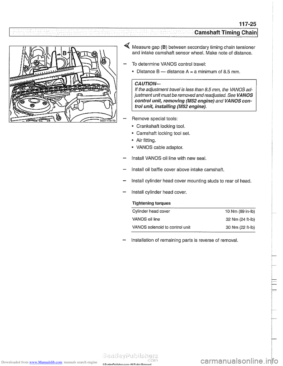
Measure gap (B) between secondary timing chain tensioner
and intake camshaft sensor wheel. Make note of distance.
To determine VANOS control travel:
Distance
I3 - distance A = a minimum of 8.5 mm
CAUTION-
If the adjustment travel is less than 8.5 mm the VANOS ad-
justment unit must be removed and readjusted. See
VANOS
control unit, removing (M52 engine)
and VANOS con-
trol unit, installing
(M52 engine).
Remove special tools:
Cranltshaft locking tool.
Camshaft
loclting tool set.
Air fitting.
* VANOS cable adaptor.
- Install VANOS oil line with new seal
- Install oil baffle cover above intake camshaft.
- Install cylinder head cover mounting studs to rear of head.
- Install cylinder head cover,
Tightening
torques
Cylinder head cover 10 Nrn (89 in-lb)
VANOS oil line
32 Nm (24 R-lb)
VANOS solenoid to control unit 30 Nrn (22 ft-lb)
- Installation of remaining parts is reverse of removal.
Page 270 of 1002
Downloaded from www.Manualslib.com manuals search engine
1 17-34
1 Camshaft Timing Chain
DOUBLE VAMOS SYSTEM
(M52 TU AND M54 ENGINES)
Double VANOS system function
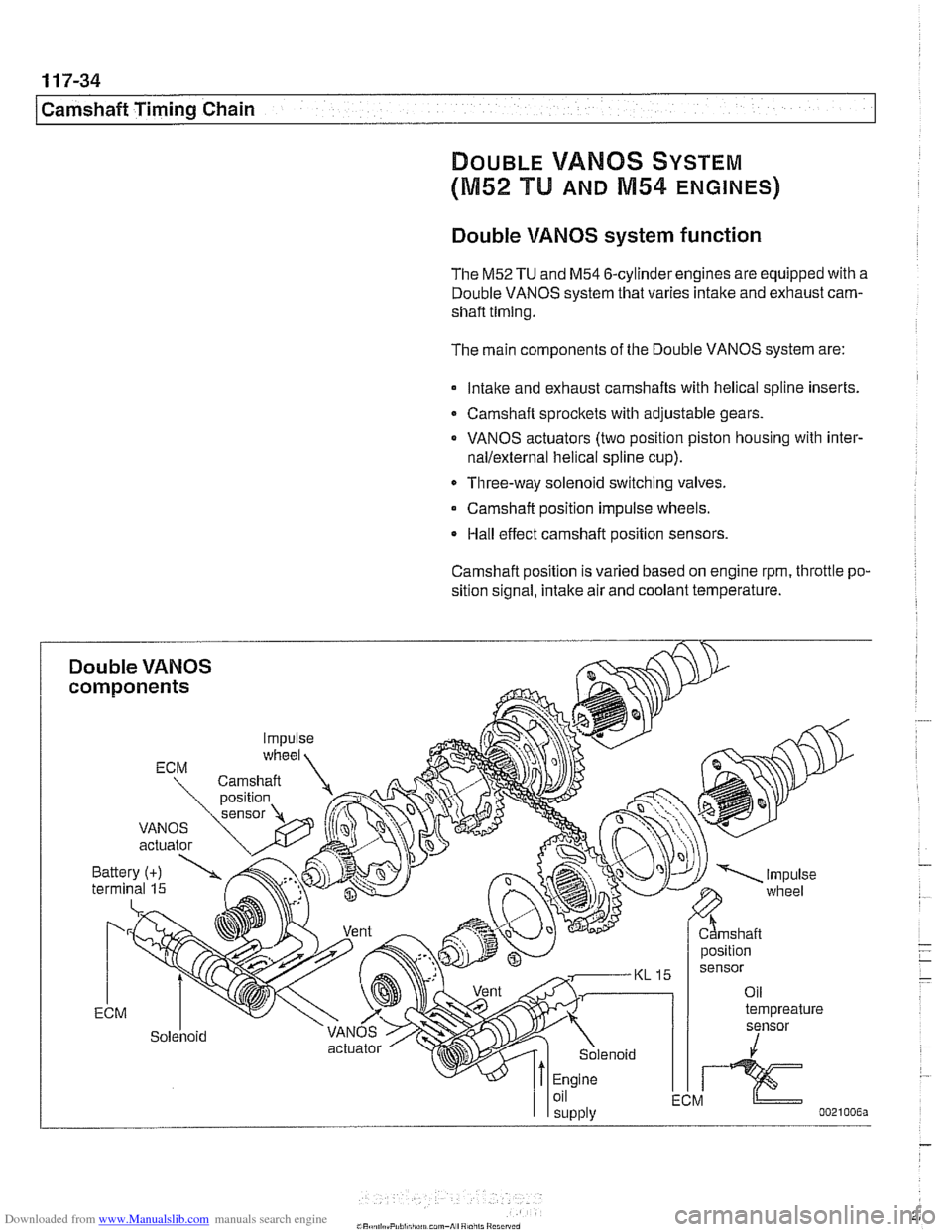
The M52TU and M54 6-cylinder engines are equipped with a
Double VANOS system that varies intake and exhaust cam-
shaft timing.
The main components of the Double VANOS system are:
lntalte and exhaust camshafts with helical spline inserts.
Camshaft sprockets with adjustable gears.
VANOS actuators (two position piston housing with
inter-
nallexternal helical spline cup).
Three-way solenoid switching valves.
Camshaft position impulse wheels.
Hall effect camshaft position sensors.
Camshaft position
IS varied based on engine rpm, throttle po-
sition signal, intake air and coolant temperature.
Page 271 of 1002
Downloaded from www.Manualslib.com manuals search engine
Camshaft Timing Chain
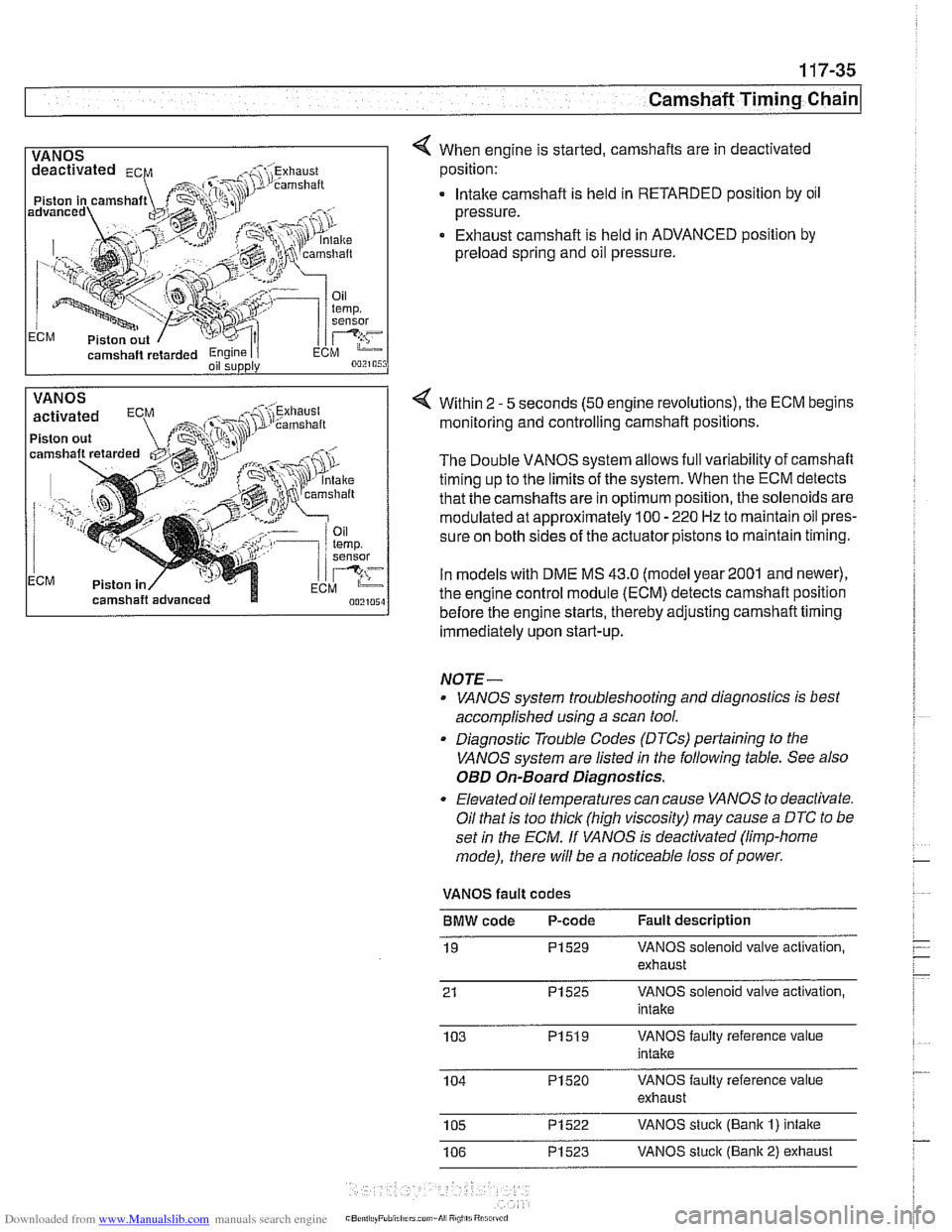
1 VANOS I 4 When engine is started, camshafts are in deactivated
camshaft
retarded Engine I i oil supply
position:
. lntalte camshaft is held in RETARDED position by oil
pressure.
Exhaust camshaft is held in ADVANCED position by
preload spring and oil pressure.
VANOS
Piston out
ECM Piston in Within 2
- 5
seconds (50 engine revolutions), the ECM begins
monitoring and controlling camshaft positions.
The Double VANOS system allows full variability of camshaft
timing up to the limits of the system. When the ECM detects
that the camshafts are in optimum position, the solenoids are
modulated at approximately 100
- 220 Hz to maintain oil pres-
sure on both sides of the actuator pistons to maintain timing.
In models with DME
MS 43.0 (model year2001 and newer),
the engine control module (ECM) detects camshaft position
before the engine starts, thereby adjusting camshaft timing
immediately upon start-up.
NOTE-
. VANOS system troubleshooting and diagnostics is best
accomplished using a scan tool.
. Diagnostic Trouble Codes (DTCs) pertaining to the
VANOS system are listed
in the following table. See also
OED On-Board Diagnostics.
Elevated oil temperatures can cause VANOS to deactivate.
Oil that is too thick (high viscosity) may cause
a DTC to be
set
in the ECM. If VANOS is deactivated (limp-home
mode), there will be a noticeable loss of power.
VANOS fault codes
BMW code P-code Fault description
19
PI529 VANOS solenoid valve activation,
exhaust
21
PI525 VANOS solenoid valve activation,
intake
103
PI519 VANOS faulty reference value
intake
104
PI520 VANOS faulty reference value
exhaust
105
PI522 VANOS stuck (Bank I) intake
106
PI523 VANOS stuck (Bank 2) exhaust