power BMW 528i 1998 E39 Workshop Manual
[x] Cancel search | Manufacturer: BMW, Model Year: 1998, Model line: 528i, Model: BMW 528i 1998 E39Pages: 1002
Page 14 of 1002
Downloaded from www.Manualslib.com manuals search engine
.
General
WARNING-
Never run the engine in tile work area unless it is well-ven-
tilated. The exhaust should be vented to the outside. Car-
bon monoxide (CO) in exhaust kills.
Remove all neckties,
scarfs, loose clothing, or jewelry
when working near a running engine or power tools.
Tuck in shirts. Tie long hair and secure it under a cap.
Severe injury can result from these things being
caugiit
in rotating parts.
Remove rings, watches, and bracelets. Aside from the
dangers of moving parts, metallic jewelry conducts
electricity and may cause shorts, sparks, burns, or
damage to the electricalsystem when accidentally con-
tacting the battery or other electrical terminals.
Disconnect the battery negative
(-) cable whenever
working on or near the fuel system or anything that is
electrically powered. Accidental electrical contact may
damage the electrical system or cause a fire.
Fuelis highly flammable. When working around fuel, do
not
smoke or work near heaters or other fire hazards.
Keep an approved fire extinguisher handy.
The fuel system is designed to retain pressure even
when the ignition is off When worlcing with the
fuelsys-
tem, loosen the fuel lines slowly to allow the residual
pressure to dissipate gradually. Take precautions to
avoid spraying fuel.
. Illuminate the worlc area adequately and safely Use a
portable safety light for worlcing inside or under the car.
A fluorescent type
light is best because it gives off less
heat. If using a light with a normal incandescent bulb,
use rough service bulbs to avoid
breakage. The hot fil-
ament of an accidentally broken bulb can ignite spilled
fuel or oil.
Keep sparks, lighted matches, and any open flame
away from the top of the battery. Hydrogen gas
emitted
by the battery is highly flammable. Any nearby source
of ignition may cause the battery to explode.
Never lay
tools or parts in the engine compartment or
on top of the battery. They may
fallinto confinedspaces
and be difficult to retrieve, become caught in belts or
other rotating parts when the engine is started, or
cause electrical shorts and damage to the electrical
system.
Page 22 of 1002
Downloaded from www.Manualslib.com manuals search engine
01 0-1 2
1 General
Information you need to know
Model
When ordering parts it is important that you know the correct
model designation for your car. Models covered in this E39
manual are the
525i,5281,530i, 540i in Sedan and Station
Wagon body styles.
Model year
This is not necessarily the same as date of manufacture or
date of sale.
A 1999 model may have been manufactured in
late 1998, and perhaps not sold until early 2000. It is still a
1999 model. Model years covered by this manual are 1997 to
2002.
Date of manufacture
This information is necessary when ordering replacement
parts or determining if any of the warranty recalls are applica-
ble to your car. The label on the driver's door below the door
latch will specify the month and year that the car was built.
Vehicle
Identification Number (VIN)
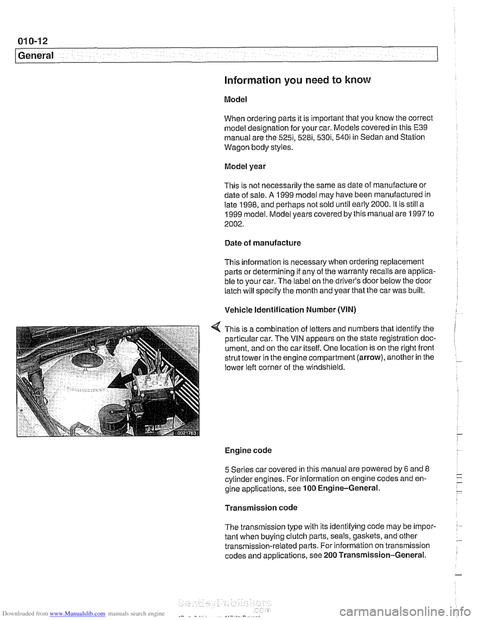
This is a combination of letters and numbers that identify the
particular car. The VIN appears on the state registration doc-
ument, and on the car itself. One location is on the right front
strut tower in the engine compartment (arrow), another in the
lower left corner of the windshield.
Engine code
5 Series car covered in this manual are powered by
6 and 8 - cylinderengines. For information on engine codes and en- -. -
gine applications, see 100 Engine-General. -
Transmission code
The transmission type with its identifying code may be
impor- :
tant when buying clutch parts, seals, gaskets, and other .- transmission-related parts. For information on transmission
codes and applications, see 200 Transmission-General.
Page 33 of 1002
Downloaded from www.Manualslib.com manuals search engine
020 Maintenance
General ........................... .02 0.2
Special tools ........................ .02 0.2
Service Interval Indicator (Sll) ........... .02 0.3
Service Interval Indicator (Sll), resetting ... .02 0.3
Inspection I, Inspection 11 ............... .02 0.5
Maintenance Tables ................ .02 0.6
Fluid and Lubricant Specifications .. .02 0.9
Fluids and lubricants ................. .02 0.10
Engine Oil Service ................ .02 0.1 I
Engine oil. checking level ............. .02 0.12
Engine oil and filter. changing .......... .02 0-13
Engine Compartment Maintenance . .02 0.14
Accelerator and linkage ............... .02 0.14
Air filter. replacing ................... .02 0.1 4
Cooling system service ............... .02 0.15
Engine drive belt service .............. .02 0.16
Idlespeed .......................... 020-19
Catalytic converter and oxygen sensors .. .02 0.19
Power steering fluid, checking level ..... .02 0.20
Spark plugs ........................ .02 0.20
Spark plugs, replacing ................ .02 0.21
Interior ventilation microfilter, replacing ... .02 0.22
Other Mechanical Maintenance ..... .02 0.22
Battery, checking. cleaning. and replacing .02 0-22
Brake fluid. replacing ................. .02 0-24
Brake pad 1 rotor wear. checking ........ .02 0.24
Brake system, inspecting ............. .02 0.25
Parking brake. checking ............... 020-25
Clutch fluid. checking ................. 020-26
Differential oil level. checking ........... 020-26
Drive axle joint (CV joint) boots. inspecting 020-27
Exhaust system. inspecting ............ 020-27
Fuel filter. replacing .................. 020-27
Fuel tank and fuel lines. inspecting ...... 020-28
Suspension. front. inspecting ........... 020-29
Suspension. rear. inspecting ........... 020-29
Tires. checking inflation pressure ........ 020-29
Tires. rotating ....................... 020-29
Transmission service. automatic ........ 020-29
Transmission service. manual .......... 020-30
Transmission fluid. checking and filling
(manual transmission)
................ 020-30
Wheels. aligning ..................... 020-30
Body and Interior Maintenance ..... 020-31
Body and hinges. lubricating ........... 020-31
Exterior washing ..................... 020-31
Interior care ........................ 020-31
Leather upholstery and trim ............ 020-31
Polishing ........................... 020-32
Seat belts .......................... 020-32
Special cleaning ..................... 020-32
Washing chassis ..................... 020-32
Waxing ............................ 020-32
Windshield wiper blade maintenance ..... 020-33
Page 39 of 1002
Downloaded from www.Manualslib.com manuals search engine
Table b. Inspection I Service (continued)
Checlt transmission and differential for
external lealts.
Check CV joint boots for damage or leaks.
Visually
check fuel tank, fuel lines, and
connections for
leaks.
New parts
Tools Required required
Check condition, position, and mounting
ol
exhaust system. Visually check and adjusl
if necessary.
Check power steering system for lealts.
Check power steering
fluid level and adjust
if necessary.
Check steering racidbox and tie rods for
tightness. Checit condition of front axle
joints, steering
linkage, and steering shaft
joints.
Check overall thickness of front and rear
bralte pads using
BMW special tool. If
replacement is necessary:
Examine brake disc surface.
Clean brake pad contact points in calipers
Grease wheel centering hubs.
Checlt thickness of parking brake linings
only when replacing rear brake shoes.
Checit operation of pariting brake and
adjust as necessary.
Checlt front control arm bushings for
damage or wear.
Check brake system connections and
lines
for leaks, damage, and incorrect
positioning Warm
engine
(~ealer service Irepair , required recommended lnformat~on
Check parking braite actuator. Adjust if
necessary
Check ail tire pressure (including spare)
and correct if necessary.
Checlt condition of tires (outer tread
surface), tread wear pattern: in case of
uneven wear, perform wheel alignment.
inspect entire body according to terms of
rust oerforation limited warrantv. (Must be
*:
4:
2 ~ perfdrmed at least every two years). I
Read out on-board diagnostic (OBD 11) fault
codes.
Checkengine coolant
system1 heater hose
connections for
leaks.
Checit coolant level and antifreeze
protection level. Add coolant as necessary.
* 100113010BD
I
170
Page 45 of 1002
Downloaded from www.Manualslib.com manuals search engine
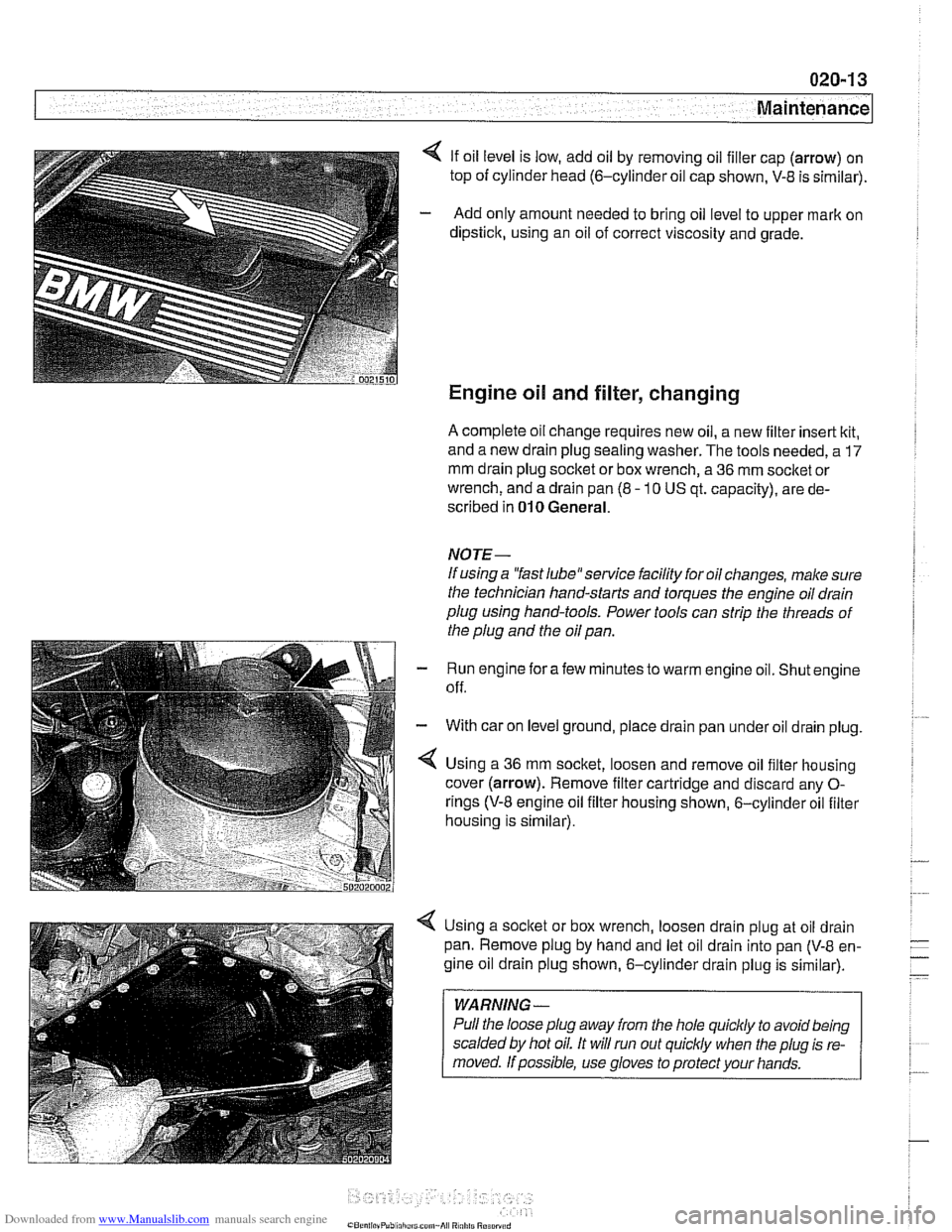
4 If oil level is low, add oil by removing oil filler cap (arrow) on
top of cylinder head
(6-cylinder oil cap shown, V-8 is sirnilar).
- Add only amount needed to bring oil level to upper mark on
dipstick, using an oil of correct viscosity and grade.
Engine oil and filter, changing
A complete oil change requires new oil, a new filter insert kit,
and a new drain plug sealing washer. The tools needed, a
17
mm drain plug socket or box wrench, a 36 mm socket or
wrench, and a drain pan (8
- 10 US qt. capacity), are de-
scribed in
010 General.
NOTE-
If using a "fast 1ube"service facility for oil changes, make sure
the technician hand-starts and torques the engine oil drain
plug using hand-tools. Power tools can strip the threads of
the plug and the oil pan.
Run engine for afew minutes to warm engine oil. Shut engine
off.
With car on level ground, place drain pan under oil drain plug.
Using a
36 mm socket, loosen and remove oil filter housing
cover (arrow). Remove filter cartridge and discard any
0-
rings (V-8 engine oil filter housing shown, 6-cylinder oil filter
housing is sirnilar).
Using a socket or box wrench, loosen drain plug at oil drain
pan. Remove plug by hand and let oil drain into pan
(V-8 en-
gine oil drain plug shown, 6-cylinder drain plug is similar).
WARNING -
Pull the loose plug away from the hole quicldy to avoid being
scalded by hot oil. It will run out
quiclcly when the plug is re-
Page 48 of 1002
Downloaded from www.Manualslib.com manuals search engine
020-1 6
Maintenance
loose, hose is damaged, or connection is dirty or corroded.
Dried coolant has achalky appearance. Hoses should be firm
and springy. Replace any hose that is cracked, has become
soft and limp, or has been contaminated by oil.
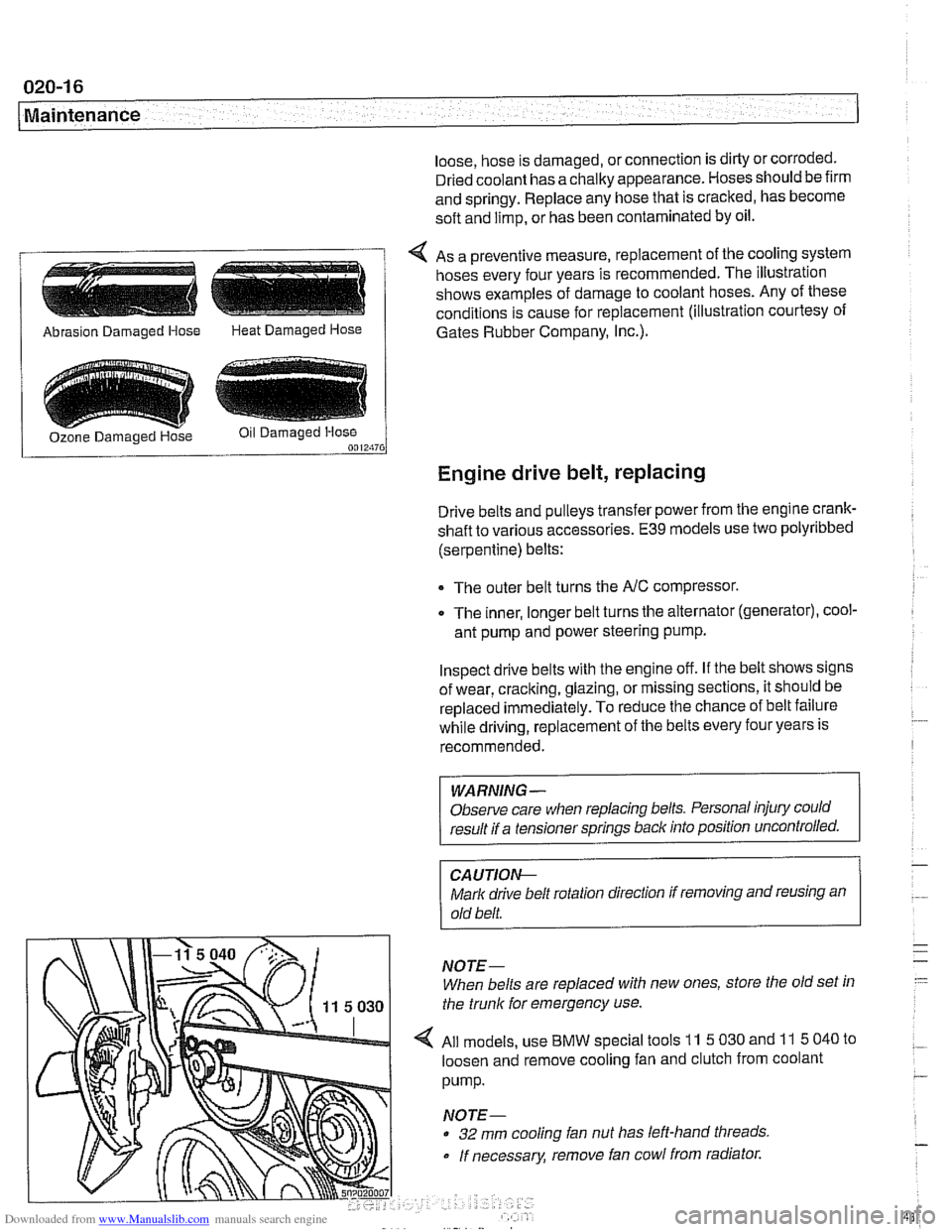
4 As a preventive measure, replacement of the cooling system
hoses every four years is recommended. The illustration
shows examples of damage to coolant hoses. Any of these
conditions is cause for replacement (illustration courtesy of
/ Abrasion Damaged Hose Heat Damaged Hose 1 Gates Rubber Company, I~c.).
Engine drive belt, replacing
Drive belts and pulleys transfer power from the engine crank-
shaft to various accessories.
E39 models use two polyribbed
(serpentine) belts:
The outer belt turns the
NC compressor.
0 The inner, longer belt turns the alternator (generator), cool-
ant pump and power steering pump.
Inspect drive belts with the engine off. If the belt shows signs
of wear, cracking, glazing, or missing sections, it should be
replaced
immediately. To reduce the chance of belt failure
while driving, replacement of the belts every four years is
recommended.
WARNING -
Observe care when replacing belts. Personal injury could
result if a tensioner springs back into position uncontrolled.
CA UTIOI\C
Mark drive belt rotation direction if removing and reusing an
old belt.
NOTE-
When belts are replaced with new ones, store the old set in
the trunk for emergency use.
All models, use
BMW special tools 11 5 030 and 11 5 040 to
loosen and remove cooling fan and clutch from coolant
pump.
NOTE-
32 mm cooling fan nut has left-hand threads
If necessary, remove fan cowl from radiator.
Page 52 of 1002
Downloaded from www.Manualslib.com manuals search engine
Maintenance
continue to operate as designed. Extending the replacement
interval may void the emission control warranty coverage.
See
180 Exhaust System for information on replacing the
oxygen sensors.
Tightening torque
Oxvoen sensor to exhaust
manifold 50 Nrn (37 ft-lb)
NOTE-
A special soclet for replacing the oxygen sensor is available
from most automotive parts stores. The soclet has
a groove
cut down one side to allow the sensor to be installed without
damaging the wire harness.
Power steering fluid, checking level
The power steering system is permanently filled and does not
have a drain. Routinely adding ATF is not required unless the
system is leaking.
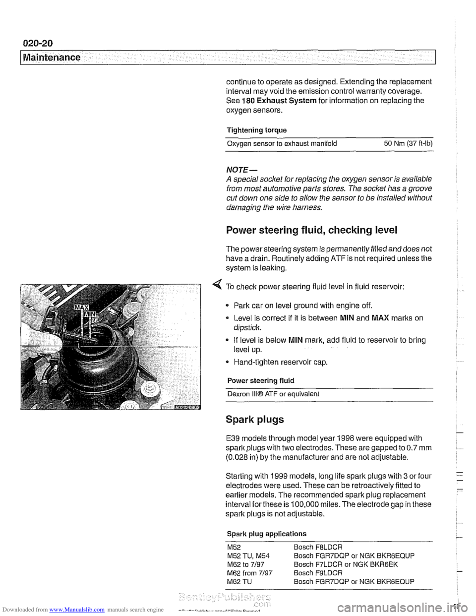
4 To check power steering fluid level in fluid reservoir:
Park car on level ground with engine off.
Level is correct
if it is between MlN and MAX marks on
dipstick.
If level is below
MlN mark, add fluid to reservoir to bring
level up.
* Hand-tighten reservoir cap.
Power steering fluid
Dexron
1iiO ATF or equivalent
Spark plugs
E39 models through model year 1998 were equipped with
spark plugs with two electrodes. These are gapped to
0.7 mm
(0.028 in) by the manufacturer and are not adjustable.
Starting with 1999 models, long life spark plugs with
3 or four
electrodes were used. These can be retroactively fitted to
earlier
models. The recommended spark plug replacement
interval
forthese is 100,000 miles.The electrode gap in these
spark plugs is not adjustable.
Spark plug applications
M52 Bosch FBLDCR
M52 TU, M54 Bosch FGR7DQP or NGK BKRBEQUP
M62 to 7/97 Bosch F7LDCR or NGK BKR6EK
M62 from 7/97 Bosch F9LDCR
M62 TU Bosch FGR7DQP or NGK BKRGEQUP
Page 54 of 1002
Downloaded from www.Manualslib.com manuals search engine
020-22 Maintenance
1
- Installation is reverse of removal, bearing in mind the
following:
Lightly lubricate new
spark plug threads with
copper-based anti-seize compound.
Thread plugs into cylinder head by hand to prevent
cross-threading.
. Be sure to reinstall and tighten coil grounds.
Tightening torque Spark plug
to cylinder head 25 Nm (18 It-lb)
Interior ventilation microfilter, replacing
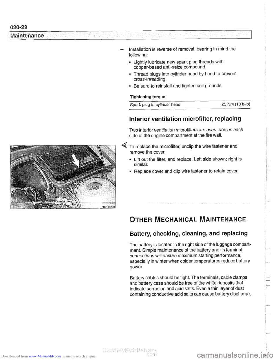
Two interior ventilation microfilters are used, one on each
side of the engine compartment at the fire wall.
< To replace the microfilter, unclip the wire fastener and
remove the cover.
Lift out the filter, and replace. Left side shown; right is
similar.
Replace cover and clip wire fastener to retain cover.
Battery, checking, cleaning, and replacing
The battery Is located in the right side of the luggage compart-
ment. Simple maintenance of the battery and its terminal
connections will ensure maximum starting periormance,
especially in winter when colder temperatures reduce battery
power.
Battery cables should be tight. The terminals, cable clamps
and battery case should be free of the white deposits that
indicate corrosion and acid salts. Even a thin layer of dust
containing conductive acid salts can cause battery discharge.
Page 71 of 1002
Downloaded from www.Manualslib.com manuals search engine
Two common causes of driveability problems are incorrect
system voltage and bad grounds.
System voltage
Digital motor electronics (DME) requires that the system (bat-
tery) voltage be maintained within a narrow range of DC volt-
age.
DC voltage levels beyond or below the operating range,
or any
AIC voltage in the electrical system can cause havoc.
When troubleshooting an illuminated MIL, make sure the bat-
tery is fully charged and capable of delivering all its power to
the electrical system. An undercharged battery can amplify
AIC alternator output ripple.
To
make a quick check of the battery charge, measure the
voltage across the battery terminals with all cables attached
and the ignition off.
Afully charged battery will measure 12.6
volts or slightly more, compared to 12.1 5 volts for a battery
with a 25% charge.
The DME system operates at low voltage and current levels,
making it sensitive to small increases in resistance. The elec-
trical system is routinely subjected to corrosion, vibration and
wear, so faults or corrosion in the wiring harness and connec-
tors are not uncommon. Check the battery terminals
forcorro-
sion or loose cable connections. See 121 Battery, Starter,
Alternator for additional information.
If a battery cable connection has no
v~sible faults but is still
suspect, measure the voltage drop across the connection. A
large drop indicates excessive resistance, meaning that the
connection is corroded, dirty, or damaged. Clean or repairthe
connection and retest.
NOTE-
For instructions on conducting a voltage drop test and other
general electrical troubleshooting information, see
600 Elec-
trical System-General.
Visually inspect all wiring, connectors, switches and fuses in
the system. Loose or damaged connectors can cause inter-
mittent problems, especially the small terminals in the ECM
connectors. Disconnect the wiring harness connectors to
check for corrosion, and use electrical cleaning spray to re-
move contaminants.
Main grounds
Good grounds are critical to proper DME operation. If a
ground connection has no visible faults but is still suspect.
measure the voltage drop across the connection. A large volt-
age drop means high resistance. Clean or repair the connec-
tion and retest.
LBuntr.yP~sbhnllcn.can#-AII A,~iltl Rcsrwsd
Page 84 of 1002
Downloaded from www.Manualslib.com manuals search engine
110-12
Engine Removal and Installation
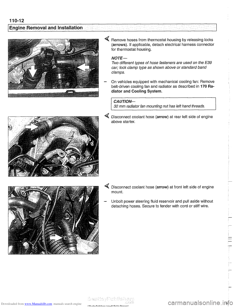
4 Remove hoses from thermostat housing by releasing locks
(arrows). If applicable, detach electrical harness connector
for thermostat housing.
NOTE-
Two different types of hose fasteners are used on the E39
car; lock clamp type as shown above or standard band
clamps.
- On vehicles equipped with mechanical cooling fan: Remove
belt-driven cooling fan and radiator as described in
170 Ra-
diator and Cooling
System.
CAUTION-
32 mm radiator fan mounting nut has left hand threads.
4 Disconnect coolant hose (arrow) at rear left side of engine
above starter.
4 Disconnect coolant hose (arrow) at front left side of engine
mount.
- Unbolt power steering fluid reservoir and pull aside without
detaching hoses. Secure to fender with cord or stiff wire.