pump BMW 528i 1998 E39 Workshop Manual
[x] Cancel search | Manufacturer: BMW, Model Year: 1998, Model line: 528i, Model: BMW 528i 1998 E39Pages: 1002
Page 3 of 1002
Downloaded from www.Manualslib.com manuals search engine
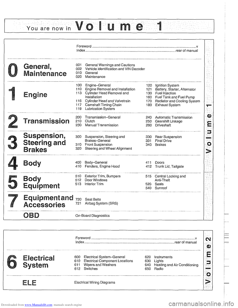
YOU are now in Volume I
I
Foreword ................... .. ........................................................................\
.......... v
Index
........................ .. ................................................................ rear of manual
General, 001 General Warnings and Cautions 002 Vehicle Identification and VIN Decoder
Maintenance OiO 020 Maintenance
Engine
100 Engine-General 110 Engine Removal and Installation
113 Cylinder Head Removal and
Installation
116 Cyiinder Head and Valvetrain 117 Camshaft Timing Chain
119 Lubrication System
200 Transmission-General
2 Transmission 210 clutch 230 ManualTransmission
I20 Ignition System
121 Battery, Starter, Alternator
130 Fuel Injection
160 Fuel Tank and Fuel Pump 170 Radiator and Cooling System
180 Exhaust System
240 Automatic Transmission
250 Gearshift Linkage 260 Driveshaft
Suspension, 300 Suspension, Steering and 330 Rear Suspension
Brakes-General 331 Final Drive
Steering and No Front Suspension 340 Brakes
320 Steering and Wheel Alignment
400 Body-General
410 Fenders, Engine Hood 411 Doors
412 Trunk Lid, Tailgate
510 Exterior Trim, Bumpers 512 Door Windows
Equipment 513 Interior Trim
7
Equipment and 720 seat Belts
Accessories 721 Airbag System (SRS)
OBD On-Board Diagnostics
. ............ ..
515 Central Lociting and
Anti-Theft
520 Seats 540 Sunroof
.................................................................... Foreword .............................. .. v
Index ................... .. ................................................................ rear of manual
Electrical
6 system
600 Electrical System-General 620 Instruments
610 Electrical Comoonent Locations 630 Liohts
611 wipers and washers 612 Switches eati in^ and Air Conditioning
Radio
. ........... ........ .........................
Electrical Wiring Diagrams
Page 25 of 1002
Downloaded from www.Manualslib.com manuals search engine
Sockets Socltets are used with a ratchet handle for speed and conve-
nience and can be combined with extensions and universal
joints (swivels) to reach fasteners more easily. The most
common socket drive sizes are
114 inch, 318 inch and 112 inch.
Sockets come in
6 point and 12 point styles. The 6 point offers
a better grip on tight nuts and bolts.
6 mm to 19 mm socltets
are the most needed sizes. Below is a list of typical bolt
diarn-
eters and the corresponding wrench sizes.
Common bolt diameters and wrench sizes
M5 8 rnrn
M6
10 rnm
M8 12rnrnor13rnrn
MI 0 17 rnrn
MI2 19 rnrn
M14 22 mm
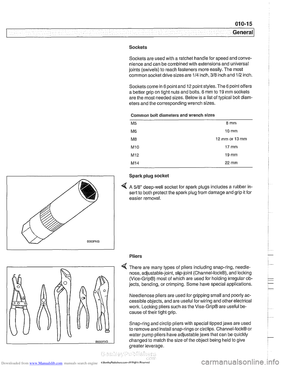
Spark plug socket
4 A 518" deep-well socket for sparlt plugs includes a rubber in-
sert to both protect the spark plug from damage and grip it for
easier removal.
Pliers
There are many types of pliers including snap-ring,
needle-
nose, adjustable-joint, slip-joint (Channel-lock@), and locking
(Vice-Grip@) most of which are used for holding irregular ob-
jects, bending, or crimping. Some have special applications.
Needlenose pliers are used for gripping small and poorly ac-
cessible objects, and are useful forwiring and other electrical
work. Locking pliers such as the Vise-Grip@ are useful be-
cause of their tight grip.
Snap-ring and circlip pliers with special tipped jaws are used
to remove and install snap-rings or circlips. Channel-lock@ or
water pump pliers have adjustable jaws that can be quicltly
changed to match the size of the object being held to give
greater leverage,
Page 34 of 1002
Downloaded from www.Manualslib.com manuals search engine
020-2
Maintenance
The information given in this repair group includes the routine
checlts and maintenance steps that are both required by
BMW under the terms of the vehicle warranty protection and
recommended by BMW to ensure long and reliable vehicle
operation.
NOTE-
Aside from keeping your car in the best possible condition,
proper maintenance plays a role in maintaining full protection
under
BMW's new car warranty coverage. If in doubt about
the terms and conditions of your car's warranty, an autho-
rized BMW dealer should be able to explain them to you.
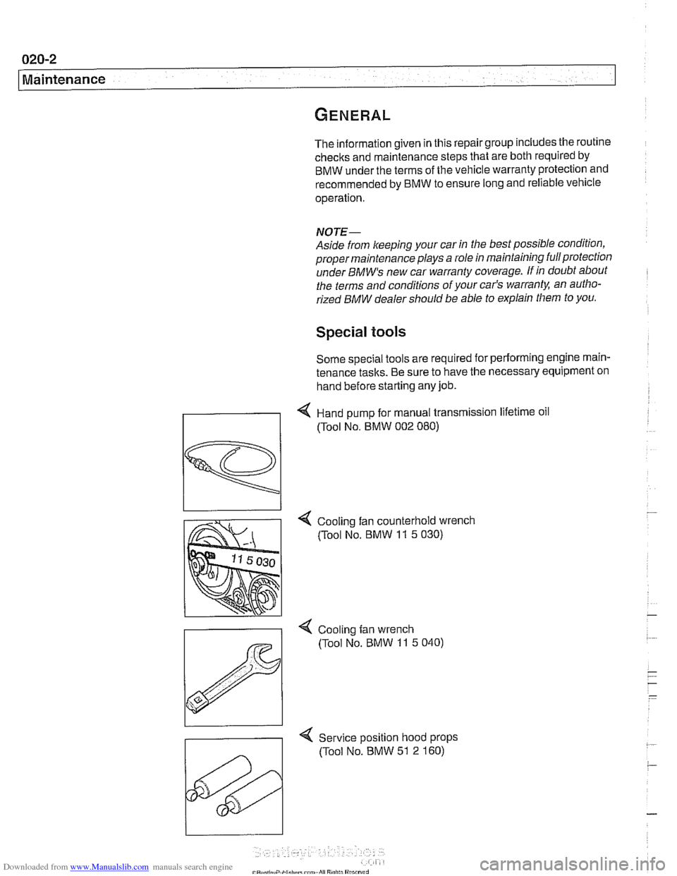
Special tools
Some special tools are required for performing engine main-
tenance tasks. Be sure to have the necessary equipment on
hand before starting any job.
4 Hand pump for manual transmission lifetime oil
71 (Tool No. BMW 002 080)
4 Cooling fan counterhold wrench
(Tool No. BMW 11 5 030)
I I 4 Coolina fan wrench
I
4 Service position hood props
(Tool No. BMW 51 2 160)
Page 48 of 1002
Downloaded from www.Manualslib.com manuals search engine
020-1 6
Maintenance
loose, hose is damaged, or connection is dirty or corroded.
Dried coolant has achalky appearance. Hoses should be firm
and springy. Replace any hose that is cracked, has become
soft and limp, or has been contaminated by oil.
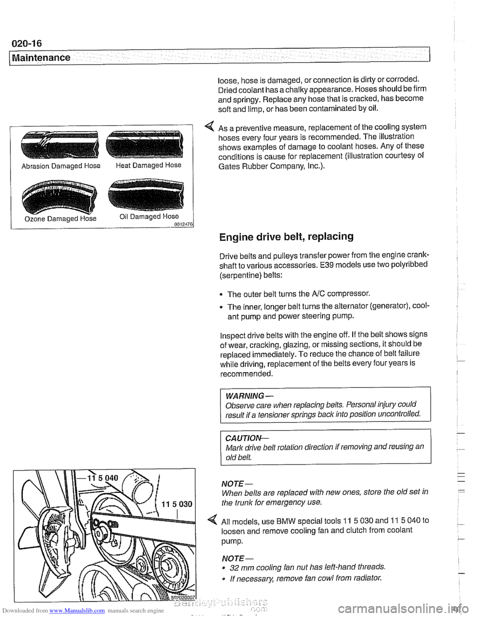
4 As a preventive measure, replacement of the cooling system
hoses every four years is recommended. The illustration
shows examples of damage to coolant hoses. Any of these
conditions is cause for replacement (illustration courtesy of
/ Abrasion Damaged Hose Heat Damaged Hose 1 Gates Rubber Company, I~c.).
Engine drive belt, replacing
Drive belts and pulleys transfer power from the engine crank-
shaft to various accessories.
E39 models use two polyribbed
(serpentine) belts:
The outer belt turns the
NC compressor.
0 The inner, longer belt turns the alternator (generator), cool-
ant pump and power steering pump.
Inspect drive belts with the engine off. If the belt shows signs
of wear, cracking, glazing, or missing sections, it should be
replaced
immediately. To reduce the chance of belt failure
while driving, replacement of the belts every four years is
recommended.
WARNING -
Observe care when replacing belts. Personal injury could
result if a tensioner springs back into position uncontrolled.
CA UTIOI\C
Mark drive belt rotation direction if removing and reusing an
old belt.
NOTE-
When belts are replaced with new ones, store the old set in
the trunk for emergency use.
All models, use
BMW special tools 11 5 030 and 11 5 040 to
loosen and remove cooling fan and clutch from coolant
pump.
NOTE-
32 mm cooling fan nut has left-hand threads
If necessary, remove fan cowl from radiator.
Page 51 of 1002
Downloaded from www.Manualslib.com manuals search engine
Maintenance
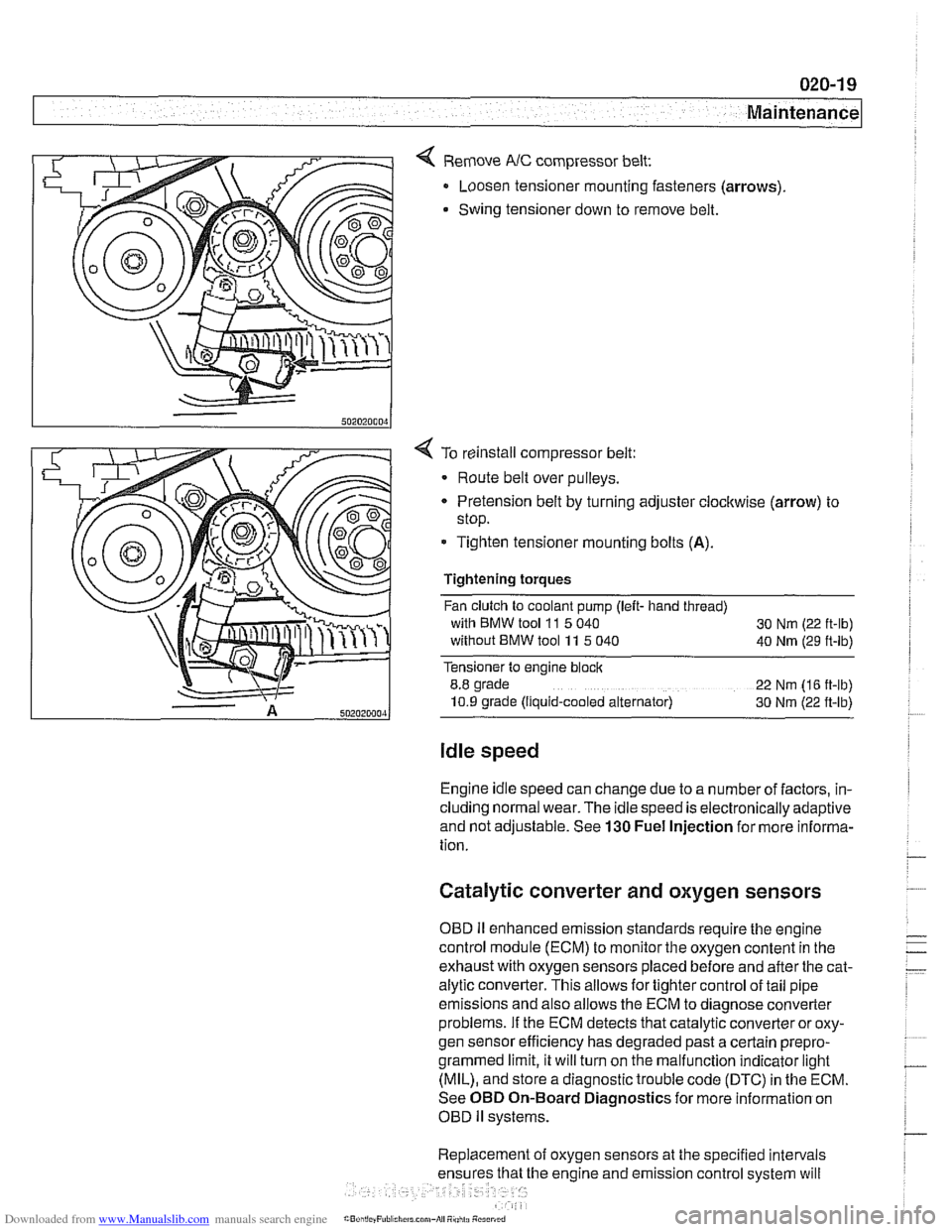
< Remove NC compressor belt:
Loosen tensioner mounting fasteners (arrows)
Swing tensioner down to remove belt.
4 To reinstall compressor belt:
Route belt over pulleys.
* Pretension belt by turning adjuster clockwise (arrow) to
stop.
- Tighten tensioner mounting bolts (A).
Tightening torques
Fan clutch to coolant pump (left- hand thread)
with BMW tool
11 5 040
30 Nm (22 ft-lb)
without BMW tool 11 5 040
40 Nm (29 ft-lb)
Tensioner to engine block
8.8 grade
22 Nm (16 ft-lb)
10.9 grade (Ilquid-cooled alternator) 30 Nm (22 ft-lb)
Idle speed
Engine idle speed can change due to a number of factors, in-
cluding normal wear. The idle speed is electronically adaptive
and not adjustable. See
130 Fuel Injection for more informa-
tion.
Catalytic converter and oxygen sensors
OBD II enhanced emission standards require the engine
control module (ECM) to monitor the oxygen content in the
exhaust with oxygen sensors placed before and after the cat-
alytic converter. This allows for tighter control of tail pipe
emissions and also allows the ECM to diagnose converter
problems. If the ECM detects that catalytic converter or oxy-
gen sensor efficiency has degraded past a certain
prepro-
grammed limit, it will turn on the malfunction indicator light
(MIL), and store a diagnostic trouble code (DTC) in the ECM.
See OBD On-Board Diagnostics for more information on
OBD
ll systems.
Replacement of oxygen sensors at the specified intervals
he engine and emission control system will
Page 60 of 1002
Downloaded from www.Manualslib.com manuals search engine
020-28
1 Maintenance
- When replacing fuel filter:
Use appropriate hose clamping device to clamp off filter
inlet and outlet hoses to lessen fuel spillage.
Loosen center clamping bracket and hose clamps on
either end of filter.
Note arrow or markings indicating direction of flow on
new filter.
Install new filter using new hose clamps
- Drain fuel filter from inlet side into a container and inspect
drained fuel.
Checlc for rust, moisture and contamination.
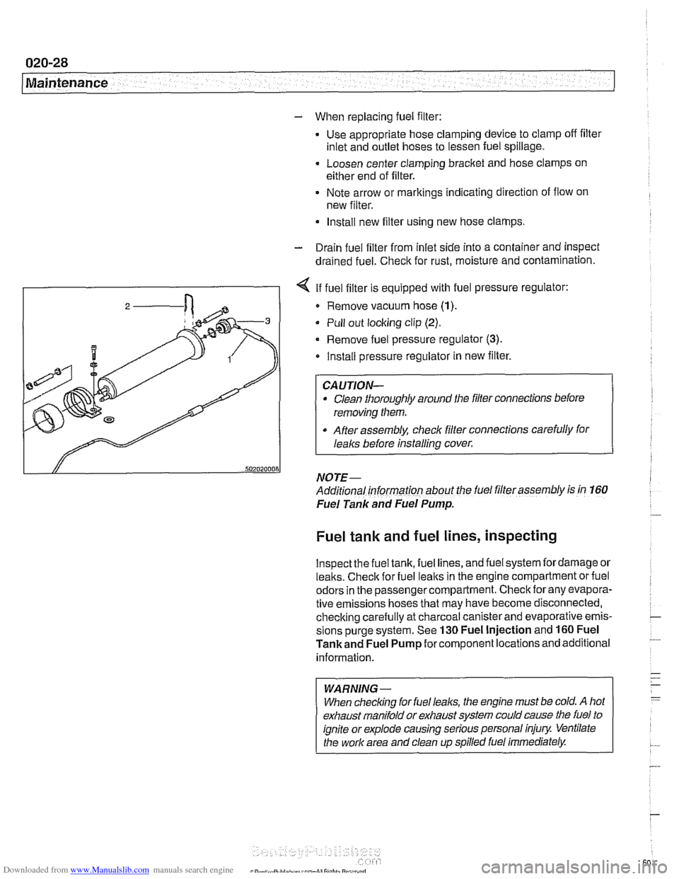
I - I < If fuel filter is equipped with fuel pressure regulator:
I 2 / Remove vacuum hose (1)
Pull out locking clip (2).
- Remove fuel pressure regulator (3).
Install pressure regulator in new filter.
Clean thoroughly around the filler connections before
removing them.
After assembly, check filter connections carefully for
I
I lealcs before installing cover.
NOTE- ~-
Additional informarion about the fuel filler assembly is in 160
Fuel Tank and Fuel Pump.
Fuel tank and fuel lines, inspecting
lnspectthe fuel tank, fuel lines, and fuel system fordamage or
lealts. Checlc for fuel lealts in the engine compartment or fuel
odors in the passenger compartment. Check for any evapora-
tive emissions hoses that may have become disconnected,
checking carefully at charcoal canister and evaporative emis-
sions purge system. See
130 Fuel Injection and 160 Fuel
Tankand Fuel Pump for component locations and additional
information.
WARNING-
When checlcing for fuel leal(s, the engine must be cold. A hot
exhaust manifold or exhaust system could cause the fuel to
ignite or explode causing serious personal injury Ventilate
the work area and clean up spilled fuel immediately.
Page 72 of 1002
Downloaded from www.Manualslib.com manuals search engine
100-6
( Engine-General
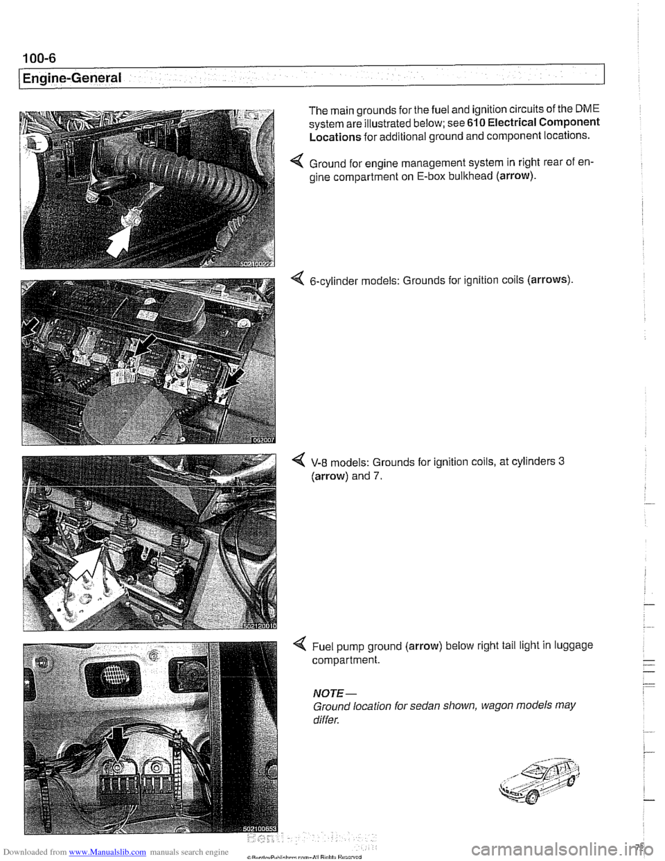
The main grounds for the fuel and ignition circuits of the DME
system are illustrated below; see 610 Electrical Component
Locations for additional ground and component locations.
4 Ground for engine management system in right rear of en-
gine compartment on E-box bulkhead (arrow).
6-cylinder models: Grounds
for ignition coils (arrows)
4 V-8 models: Grounds for ignition coils, at cylinders 3
(arrow) and 7.
4 Fuel pump ground (arrow) below right tail light in luggage
compartment.
NOTE-
Ground location for sedan shown, wagon models may
differ.
Page 85 of 1002
Downloaded from www.Manualslib.com manuals search engine
Engine Removal and Installation
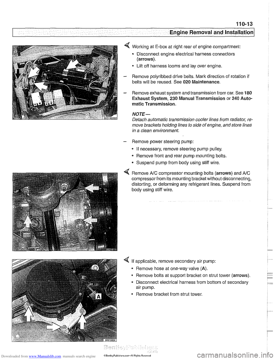
4 Working at E-box at right rear of engine compartment:
Disconnect engine electrical harness connectors
(arrows).
Lift off harness looms and lay over engine.
- Remove polyribbed drive belts. Mark direction of rotation if
belts will be reused. See 020 Maintenance.
- Remove exhaust system and transmission from car. See 180
Exhaust System, 230 Manual Transmission or 240 Auto-
matic Transmission.
NOJE-
Detach automatic transmission cooler lines from radiator, re-
move brackets holding lines to side of engine, andstore lines
in a clean environment.
- Remove power steering pump:
If necessary, remove steering pump pulley.
Remove front and rear pump mounting bolts.
Suspend pump from body using stiff wire.
4 Remove A/C compressor mounting bolts (arrows) and AIC
compressor from its mounting bracketwithoutdisconnecting,
distorting, or deforming any refrigerant lines. Suspend from
body using stiff wire.
4 If applicable, remove secondary air pump:
Remove hose at one-way valve
(A).
Remove bolts at support bracket on strut tower (arrows).
- Disconnect electrical harness from bottom of secondary
air pump.
Remove bracket from strut tower.
Page 87 of 1002
Downloaded from www.Manualslib.com manuals search engine
110-15
Engine Removal and lnstallation
- Installation is reverse of removal, noting the following:
Replace all gaskets. O-rings and seals.
Use new fuel injector seals
Check that engine drive belts properly engage pulley
grooves.
Inspect O-ring seal between mass air flow sensor and air
filter housing. To facilitate reassembly, coat seal with acid-
free grease.
Change engine oil and filter and
check all other fluid levels.
See
020 Maintenance.
Refill and bleed cooling system. See
170 Radiator and
Cooling System.
CAUTION--
When reattaching throttle assembly harness connectoc con-
nector is
fuNy tightened when arrows on connector and plug
line up.
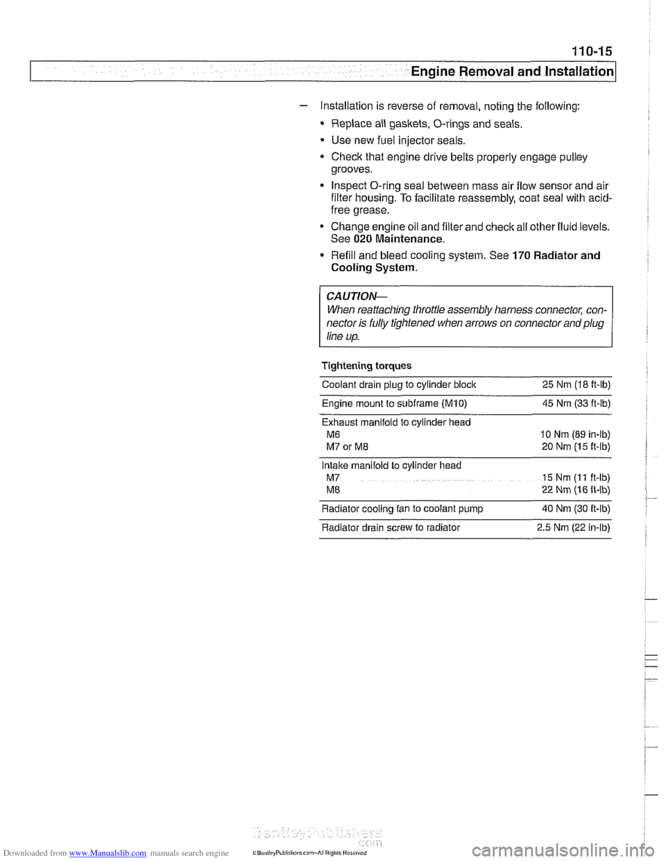
Tightening torques
Coolant drain plug to cylinder block
25 Nm (18 ft-lb)
Engine mount to
subframe (M10) 45 Nm (33 ft-ib)
Exhaust manifold to cylinder head
M6 10 Nm (89 in-lb)
M7 or ME 20 Nm (15 ft-lb)
Intake manifold to cylinder head
M7 15 Nm (I 1 ft-lb)
ME 22 Nm (16 ft-lb)
Radiator cooling fan to coolant pump
40 Nm (30 ft-lb)
Radiator drain screw to radiator
2.5 Nm (22 in-lb)
Page 92 of 1002
Downloaded from www.Manualslib.com manuals search engine
11 0-20
Engine Removal and Installation
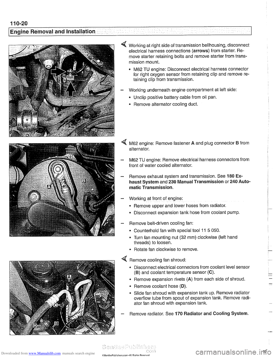
Working at right side of transmission bellhousing, disconnect
electrical harness connections (arrows) from starter. Re-
move starter retaining bolts and remove starter from trans-
mission mount.
M62 TU engine: Disconnect electrical harness connector
for right oxygen sensor from retaining clip and remove re-
taining clip from transmission.
- Working underneath engine compartment at left side:
Unclip positive battery cable from oil pan.
. Remove alternator cooling duct.
4 M62 engine: Remove fastener A and plug connector B from
alternator.
- M62 TU engine: Remove electrical harness connectors from
front of water cooled alternator.
- Remove exhaust system and transmission. See 180 Ex-
haust System and 230 Manual Transmission or 240 Auto-
matic Transmission.
- Working at front of engine:
Remove upper and lower hoses from radiator.
D~sconnect expansion tank hose from coolant pump.
- Remove belt-driven cooling fan:
Counterhold fan with special tool
11 5 050.
Turn fan mounting nut (32 mm) clockwise (left hand
threads) to loosen.
Rotate fan clockwise to remove.
Remove cooling fan shroud:
Disconnect electrical connectors from coolant level sensor
(B) and coolant temperature sensor (C).
. Remove expansion rivets (A) from each side of shroud
Remove coolant hose
(D).
Slide fan shroud with expansion tank up. Remove radiator
overflow tube from spout of expansion tank. Remove radi-
ator fan shroud with expansion tank.
Remove radiator. See
170 Radiator and Cooling System.