replace control arm BMW 528i 1998 E39 Workshop Manual
[x] Cancel search | Manufacturer: BMW, Model Year: 1998, Model line: 528i, Model: BMW 528i 1998 E39Pages: 1002
Page 39 of 1002
Downloaded from www.Manualslib.com manuals search engine
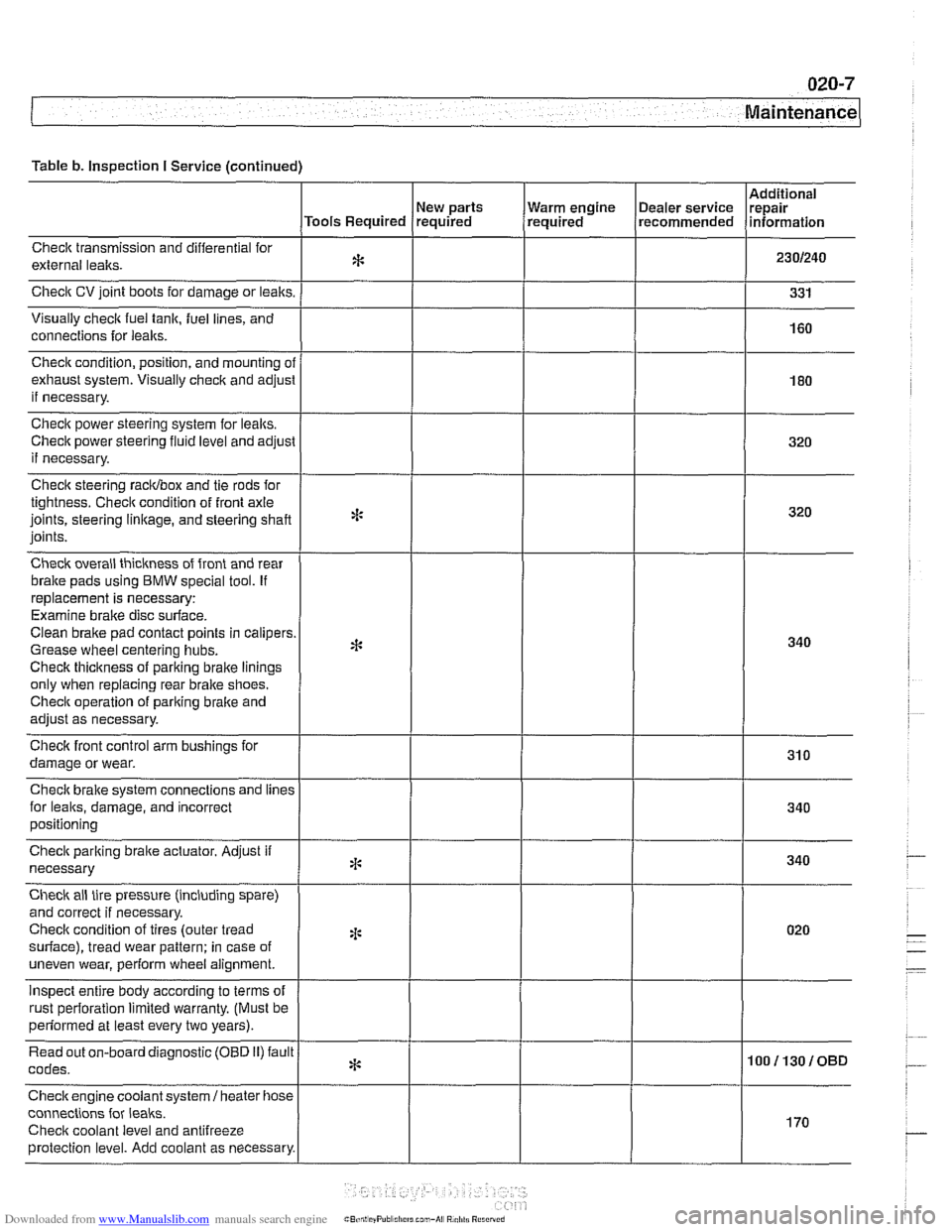
Table b. Inspection I Service (continued)
Checlt transmission and differential for
external lealts.
Check CV joint boots for damage or leaks.
Visually
check fuel tank, fuel lines, and
connections for
leaks.
New parts
Tools Required required
Check condition, position, and mounting
ol
exhaust system. Visually check and adjusl
if necessary.
Check power steering system for lealts.
Check power steering
fluid level and adjust
if necessary.
Check steering racidbox and tie rods for
tightness. Checit condition of front axle
joints, steering
linkage, and steering shaft
joints.
Check overall thickness of front and rear
bralte pads using
BMW special tool. If
replacement is necessary:
Examine brake disc surface.
Clean brake pad contact points in calipers
Grease wheel centering hubs.
Checlt thickness of parking brake linings
only when replacing rear brake shoes.
Checit operation of pariting brake and
adjust as necessary.
Checlt front control arm bushings for
damage or wear.
Check brake system connections and
lines
for leaks, damage, and incorrect
positioning Warm
engine
(~ealer service Irepair , required recommended lnformat~on
Check parking braite actuator. Adjust if
necessary
Check ail tire pressure (including spare)
and correct if necessary.
Checlt condition of tires (outer tread
surface), tread wear pattern: in case of
uneven wear, perform wheel alignment.
inspect entire body according to terms of
rust oerforation limited warrantv. (Must be
*:
4:
2 ~ perfdrmed at least every two years). I
Read out on-board diagnostic (OBD 11) fault
codes.
Checkengine coolant
system1 heater hose
connections for
leaks.
Checit coolant level and antifreeze
protection level. Add coolant as necessary.
* 100113010BD
I
170
Page 510 of 1002
Downloaded from www.Manualslib.com manuals search engine
Radiator and Cooling System
Cooling system, bleeding
Trapped air in the cooling system can prevent proper coolant
circulation and overheating. Wheneverthe coolant is drained
and filled, bleed the cooling system to remove trapped air.
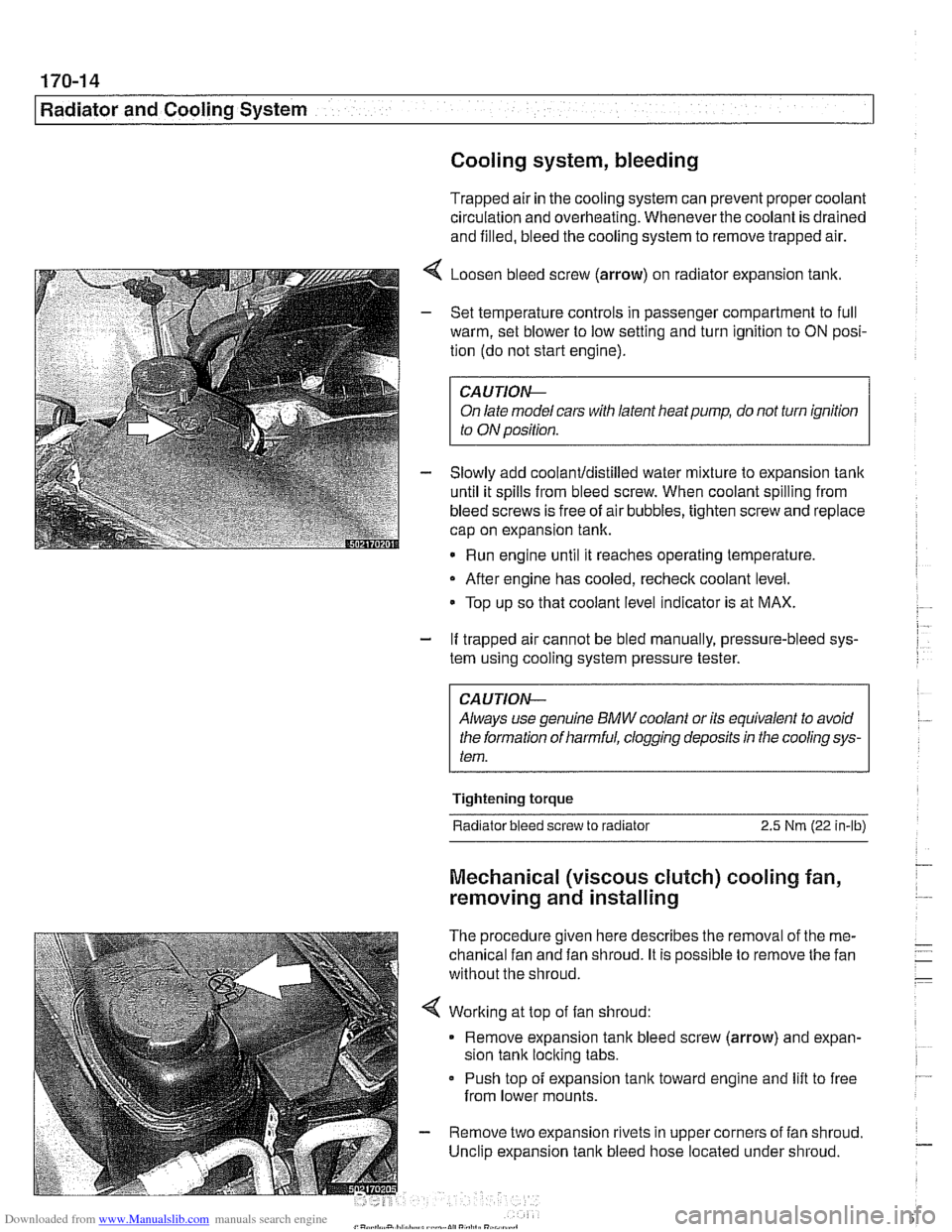
4 Loosen bleed screw (arrow) on radiator expansion tank.
- Set temperature controls in passenger compartment to full
warm, set blower to low setting and turn ignition to
ON posi-
tion (do not start engine).
CAUTIOIG
On late model cars with latent heat pump, do not turn ignition
to ON position.
- Slowly add coolanUdistilled water mixture to expansion tank
until it spills from bleed screw. When coolant spilling from
bleed screws is free of air bubbles, tighten screw and replace
cap on expansion tank.
Run engine until it reaches operating temperature,
- After engine has cooled, recheck coolant level.
Top up so that coolant level indicator is at MAX.
- If trapped air cannot be bled manually, pressure-bleed sys-
tem using cooling system pressure tester.
CA UTlON--
Always use genuine BMW coolant or its equivalent to avoid
the formation of harmful, clogging deposits
in the cooling sys-
tem.
Tightening torque
Radiator bleed screw to radiator 2.5 Nm (22 in-lb)
Mechanical (viscous clutch) cooling fan,
removing and installing
The procedure given here describes the removal of the me-
chanical fan and fan shroud. It is possible to remove the fan
without the shroud.
< Working at top of fan shroud:
Remove expansion tank bleed screw (arrow) and expan-
sion tank locking tabs.
Push top of expansion
tank toward engine and lift to free
from lower mounts.
- Remove two expansion rivets in upper corners of fan shroud.
Unclip expansion tank bleed hose located under shroud.
Page 626 of 1002
Downloaded from www.Manualslib.com manuals search engine
300-6
/Suspension, Steering and Brakes - General
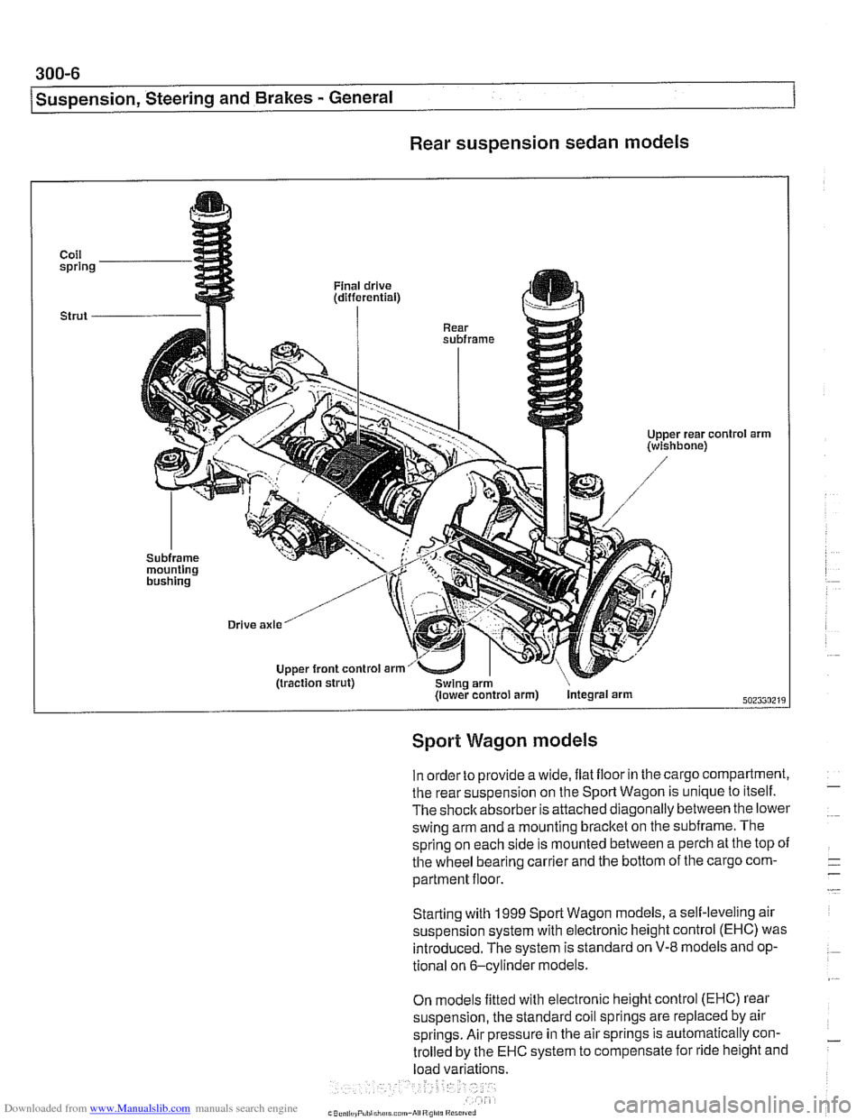
Rear suspension sedan models
Coil spring
Strut
-
'01 arm
Sport Wagon models
In order to provide a wide, ilat iloor in the cargo compartment,
the rear suspension on the Sport Wagon is unique to itself.
The shoclcabsorber is attached diagonally between the lower
swing arm and a mounting bracket on the subframe. The
spring on each side is mounted between a perch at the top
oi
the wheel bearing carrier and the bottom of the cargo com-
partment floor.
Starting with
1999 Sporl Wagon models, a self-leveling air
suspension system with electronic height control (EHC) was introduced. The system is standard on
V-8 models and op-
tional on 6-cylinder models.
On models fitted with electronic height control (EHC) rear
suspension, the standard coil springs are replaced by air
springs. Air pressure in the air springs is automatically con-
trolled by the
EHC system to compensate for ride height and
load variations.
Page 630 of 1002
Downloaded from www.Manualslib.com manuals search engine
300-1 0
/Suspension, Steering and Brakes - General
The steering system features variable power assist provided
by an engine-driven hydraulic pump.
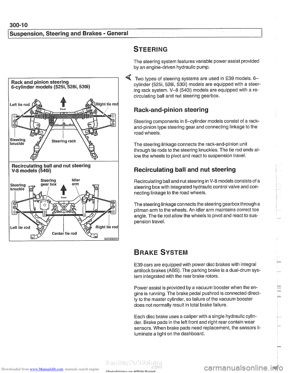
Rack and pinion steering
6-cylinder models
(525i, 5281, 5300
Two types of steering systems are used in E39 models. 6-
cylinder (525i, 5281, 530i) models are equipped with a steer-
ing rack system. V-8
(540i) models are equipped with a re-
circulating ball and nut steering gearbox.
Rack-and-pinion steering
Steering components in 6-cylinder models consist of a rack-
and-pinion type steering gear and connecting linltage to the
road wheels.
The steering linkage connects the rack-and-pinion unit
through tie rods to the steering knucltles. The tie rod ends al-
low the wheels to pivot and react to suspension travel.
Recirculating ball and nut steering
V-8 models
(540i)
I
Recirculating ball and nut steering
Recirculating ball and nut steering in V-8 models consists of a
steering box with integrated hydraulic control valve and con-
necting linkage to the road wheels.
Thesteering linkageconnects the steering gearbox through a
pitman arm to the wheels. An idler arm maintains correct toe
angle. The tie rod allow the wheels to pivot and react to sus-
pension travel.
E39 cars are equipped with power disc brakes with integral
antilock brakes (ABS). The parking bralte is a dual-drum sys-
tem integrated with the rear brake rotors.
Power assist is provided by a vacuum booster when the en-
gine is running. The brake pedal
pushrod is connected direct-
ly to the master cylinder, so failure of the vacuum booster
does not normally result in total
bralte failure.
Each disc bralte uses a caliper with a single hydraulic cylin-
der. Brake pads in the left front and right rear contain wear
sensors. When brake pads need replacement, the sensors il-
luminate a light on the dashboard.
Page 640 of 1002
Downloaded from www.Manualslib.com manuals search engine
31 0-4
I Front Suspension
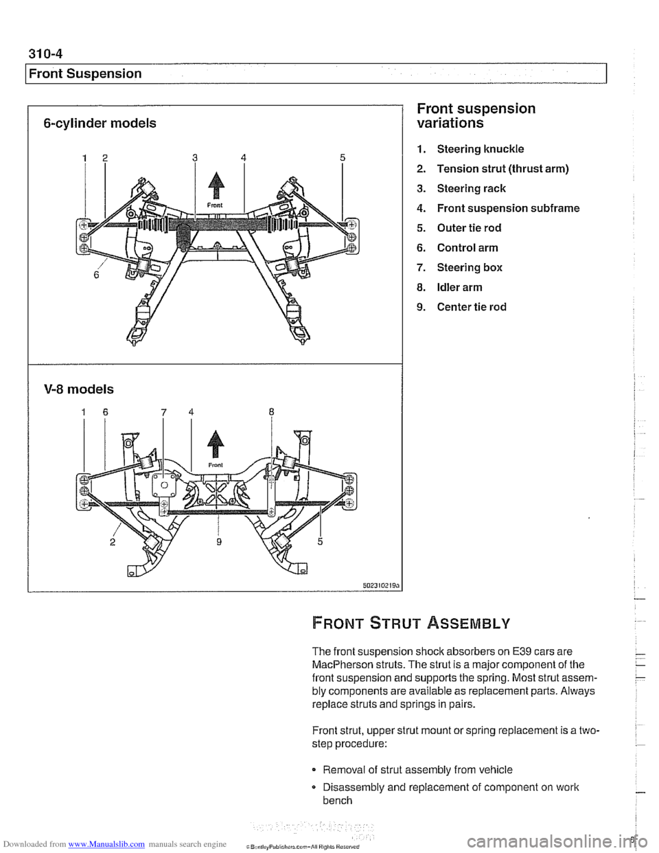
6-cylinder models
12 3 4 5
V-8 models
16 7 4
Front suspension
variations
1. Steering knuckle
2. Tension strut (thrust arm)
3. Steering rack
4. Front suspension
subframe
5. Outer tie rod
6. Control arm
7. Steering box
8. Idler arm
9. Center tie rod
The front suspension
shoclc absorbers on E39 cars are
MacPherson struts. The strut is a major component of the
front suspension and supports the spring. Most strut assem-
bly components are available as replacement parts. Always
replace struts and springs in pairs.
Front strut, upper strut mount or spring replacement is a two-
step procedure:
Removal of strut assembly from vehicle
Disassembly and replacement of component on
work
bench
Page 648 of 1002
Downloaded from www.Manualslib.com manuals search engine
/~ront Susaension
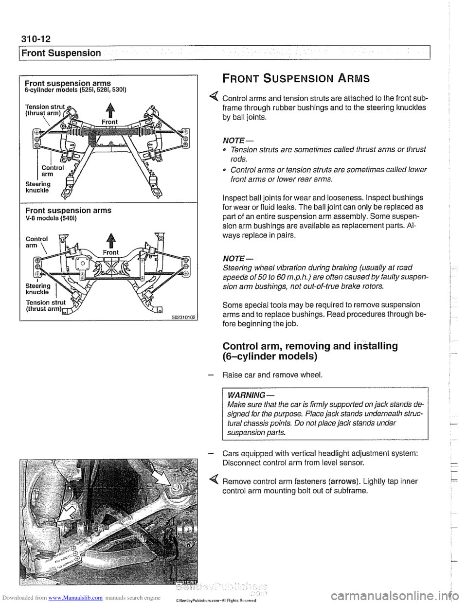
Front suspension arms FRONT SUSPENSION ARMS
Scyllnder models (5251,5281,530i)
Control arms and tension struts are attached to the front sub-
Front suspension arms V-8 models (5401)
frame through rubber bushings and to the steering ltnuckles
by ball joints.
NOTE-
Tension struts are sometimes called thrust arms or thrust
rods.
Control arms or tension struts are sometimes called lower
front arms or lower rear arms.
Inspect ball joints for wear and looseness. lnspect bushings
for wear or fluid
lealts. The ball joint can only be replaced as
part of an entire suspension arm assembly. Some suspen-
sion arm
bushinas are available as re~lacement Darts. Al-
ways replace in pairs
NOTE-
Steering wheel vibration during braking (usually at road
speeds of
50 to 60 m.p.h.) are often causedby faulty suspen-
sion arm bushings, not out-of-true brake rotors.
Some special tools may be required to remove suspension
arms and to replace bushings. Read procedures through be-
fore beginning the job.
Control arm, removing and installing
(6-cylinder models)
- Raise car and remove wheel
Male sure
that the car is firmly supported on jack stands de-
signed for the purpose. Place jack stands underneath struc-
tural chassis points. Do not place jack stands under
suspension
parfs.
Cars equipped with vertical headlight adjustment system:
Disconnect control arm from level sensor.
Remove control arm fasteners (arrows). Lightly tap inner
control arm mounting bolt out of subframe.
Page 688 of 1002
Downloaded from www.Manualslib.com manuals search engine
I Steering and Wheel Alignment
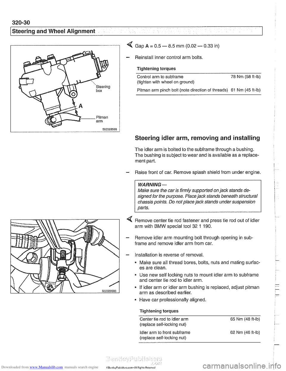
I I 4 Gap A = 0.5 - 8.5 mm (0.02 - 0.33 in)
- Reinstall inner control arm bolts
Tightening torques
Control arm to
subframe 78 Nm (58 it-lb)
(tighten with wheel on ground)
Pitman arm pinch bolt (note direction of threads) 61 Nm (45 ft-lb)
Steering idler arm, removing and installing
The idler arm is bolted to the subframe through a bushing.
The bushing is subject to wear and is available as a replace-
ment part.
- Raise front of car. Remove splash shield from under engine.
WARNING -
Male sure the car is firmly supported on jaclc stands de-
signed for the purpose. Place jack stands beneath structural
chassis points. Do not place jack stands under suspension
parts.
4 Remove center tie rod fastener and press tie rod out of idler
arm with
BMW special tool 32 1 190.
- Remove idler arm mounting bolt through opening in sub-
frame and remove idler arm from car.
- Installation is reverse of removal.
Make sure all thread bores, bolts, nuts and mating surfac-
es are clean.
Use new self
loclting nuts to mount idler arm to subframe
and center tie rod to idler arm.
If idler arm or idler arm bushing is replaced, adjust
pitman
arm as described earlier.
Have car professionally aligned.
Tightening torques
Center tie rod to idler arm 65 Nm (48 ft-ib)
(replace self-locking nut)
Idler arm to front subirame
(replace self-locking nut) 62
Nm (46 it-lb)
Page 697 of 1002
Downloaded from www.Manualslib.com manuals search engine
330 Rear Suspension
General . . . . . . . . . . . . . . . . . . . . . . . . . . . ,330-2
Special tools . . . . . . . . . . . . . . . . . . . . . . . . ,330-2
Rear suspension variations . . . . . . . . . . . . ,330-4
Rear Struts and Springs
(sedan models)
. . . . . . . . . . . . . . . . . . . . ,330-5
Rear strut assembly, removing
and installing
. . . . . . . . . . . . . . . . . . . . . . . ,330-5
Rear strut assembly, disassembling
and assembling
. . . . . . . . . . . . . . . . . . . . . ,330-7
Rear Shock Absorbers and
Springs (Sport Wagon models)
. . . . . ,330-9
Rear shock absorber, removing
and installing
. . . . . . . . . . . . . . . . . . . . . . . ,330-9
Coil spring, removing and installing . . . . . ,330-1 1
Air spring, removing and installing
. . . . . . ,330-12
Rear Suspension Arms,
Subframe and Bushings . . . . . . . . . . ,330-13
Rear suspension arm components . . . . . . ,330-1 3
Swing arm, removing and installing (sedan models)
. . . . . . . . . . . . . . . . . . . . . ,330-1 4
Swing arm, removing and installing (Sport Wagon models)
. . . . . . . . . . . . . . . ,330-16
Swing arm ball joint, replacing . . . . . . . . . ,330-1 9
Upper rear control arm, removing
and installing (sedan models)
. . . . . . . . . . .330-22
Upper rear control arm, removing
and installing (Sport Wagon models)
. . . . .330-23
Upper front control arm (traction strut),
removing and installing
. . . . . . . . . . . . . . . ,330-25
Rear axle assembly, removing and
installing (sedan models)
. . . . . . . . . . . . . ,330-26
Rear axle assembly, removing and
installing (Sport Wagon models)
. . . . . . . ,330-28
Rear subframe mounting bushings,
removing and installing
. . . . . . . . . . . . . . . .330-31
Rear Wheel Bearings . . . . . . . . . . .
Rear wheel bearing carrier, removing
and installing (sedan models)
. . . . . . .
Rear wheel bearing carrier, removing
and installing (Sport Wagon models)
. .
Rear wheel bearing, replacing . . . . . . .
Rear Stabilizer Bar
Stabilizer bar, removing and installing .
Stabilizer bar link, removing
and installing
. . . . . . . . . . . . . . . . . . . .
Electronic Height Control (EHC)
Component Replacement
. . . . . . .
Electronic height control (EHC)
components
.....................
Air compressor pump relay, removing
and installing
. . . . . . . . . . . . . . . . . . . .
EHC control module, removing
and installing
. . . . . . . . . . . . . . . . . . . .
Air supply unit, removing and installing
Ride height sensor, removing
and installing
. . . . . . . . . . . . . . . . . . . .
Page 705 of 1002
Downloaded from www.Manualslib.com manuals search engine
--
C. -- -- - -- Rear ~us~ensionl
Depending on year and model applications, the Sport Wagon
rear suspension may be equipped with:
Conventional shock absorbers and coil springs
Electronic height control (EHC) system which incorporates
air springs
NOTE-
. Suspension and EHC troubleshooting is covered in 300
Suspension, Steering and Brakes-General.
EHC system repairs, other than air spring replacement,
are covered in Electronic height control
(EHC) compo-
nent replacement.
Replace shock absorbers and springs in pairs only.
Rear shock absorber, removing and
installing
- Raise car and remove rear wheels,
WARNING-
Male sure that the car is firmly supported on jack stands de-
signed for the purpose. Place jack stands underneath struc-
tural chassis points. Do not place
jack stands under
suspension parts.
CAUTION-
If working on a vehicle with compressedairshock absorbers,
disable air supply pump by disconnecting electrical plug be-
fore performing any repairs. Pump is located beneath a cover
under the spare tire in the floor of the cargo compartment.
- Support swing arm from below
CAUTIOG
The shock absorber prevents the drive axle and wlieel bear-
ing carrier from dropping too far. Supporting the wheel bear-
ing carrier before disconnecting the shock absorber
mounting fasteners prevents damage to the
brake hose,
parking
brake cable and drive axle CVjoints.
- Working in cargo compartment, remove carpet. Remove tri-
angular upper shock mount covers located beside spare tire
well.
- If applicable: Detach air supply line from shock absorber.
Plug ports and lines to keep out dirt.
Page 709 of 1002
Downloaded from www.Manualslib.com manuals search engine
330-1 3
Rear Suspension
1 1 4 Check roll fold of air spring (arrows). Reinstall only if roll fold
is undamaged and formed correctly.
- To install air spring:
Check sealing O-rings at air spring inlet. Replace
if dam-
aged. Do not grease O-rings. Reinstall protective plug.
* Install spring above suspension subframe. Make sure ec-
centric lug at bottom of air spring fits in recess of
subframe
spring seat.
Reattach top spring mounting clips.
- Reattach air line connections.
- Remainder of installation is reverse of removal.
Tightening torques
Air line connection
2 Nm (1 8 in-lb)
Air spring
to wheel bearing carrier 20 Nm (1 5 ft-lb)
Road
wheel to hub 120 510 Nm (89-F-7 ft-lb)
REAR SUSPENSION ARMS,
SUBFRAME AND BUSHINGS
A damaged suspension arm orworn bushings will change the
rear wheel alignment and may adversely affect handling and
stability.
WARNING-
Do not attempt to straighten a damaged suspension arm.
Bending or heating may
weaken the original part. Always re-
olace a damaoed susoension arm.
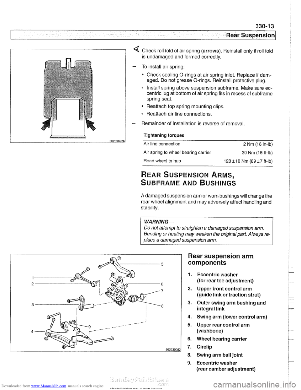
Rear suspension arm
components
1. Eccentric washer
(for rear toe adjustment)
2. Upper front control arm
(guide link or traction strut)
3. Outer swing arm bushing and
integral link
4. Swing arm (lower control arm)
5. Upper rear control arm
(wishbone)
6. Wheel bearing carrier
7. Circlip
8. Swing arm ball joint
9. Eccentric washer
(rear camber adjustment)