Ac control module BMW 528i 1999 E39 Workshop Manual
[x] Cancel search | Manufacturer: BMW, Model Year: 1999, Model line: 528i, Model: BMW 528i 1999 E39Pages: 1002
Page 952 of 1002
Downloaded from www.Manualslib.com manuals search engine
I Airbag System (SRS)
Two-stage airbag (MRS Ill)
Beginning with 2000 model year (911 999 production) the front
airbags were changed to a two-stage style airbag. This en-
sures that the force of
airbag inflation is not greater than nec-
essary to provide
protection. The airbags are designed to
Drovide "soit" de~lovment if the acceleration sensor detects a
iow-speed impact, and "hard deployment in higher speed im-
pacts.
NOTE-
A two-stage passenger airbag was used on cars built be-
tween
9/1998 and 3/1999. This pre-smart technology airbag
used two ignition stages. Stage one is designed to ignite first
during an impact. Stage two ignites after a timed period, as
programmed in the MRS
I1 control module.
Airbag indicator light
The MRS control module detects and stores system status
The
airbag indicator light in the instrument cluster displays
the status of the
airbag system when the ignition key is in "ac-
cessory" or
ON positions.
System normal: lndicator light comes on briefly, then goes
out.
- System malfunction: lndicator light fails to come on.
System malfunction: lndicator light comes on briefly, goes
out and lights up again.
The
airbag indicator light also comes on if the seat belt pyro-
technic tensioners have been triggered.
Page 953 of 1002
Downloaded from www.Manualslib.com manuals search engine
Airbag System (SRS)~
Warnings
When servicing airbag equipped cars, the following precau-
tions must be
observed to prevent personal injury.
WARNING-
. If the airbag indicator light is on, there is a risk that the air-
bags will not be triggered in case of an accident Be sure
to have the system inspected and repaired immediately
Airbag(s) are inflated by an explosive device. Handled
improperly or witliout adequate safeguards, the system
can be very dangerous. Special precautions must be
observed prior to any work at or near the airbags.
0 The airbag is a vehicle safety system. Serious injury
may result if system service is attempted by persons
unfamiliar with the BMW
MRS and its approved service
procedures. BMW advises that all inspection and ser-
vice be performed by an authorized BMW dealer.
Always disconnect the battery and cover the negative
(-) battery terminal with an insulator before starting di-
agnostic, troubleshooting or service
work not associat-
ed
with the airbags, and before doing any welding on
the car.
0 After disconnecting the battery, wait 5 seconds before
beginning work on
airbag components.
* If an airbag has been activated due to an accident,
BMW specifies that
airbag components be replaced.
For more information on post-collision
airbag service,
see an authorized BMW dealer.
Do not fire an
airbag unit prior to disposal. It must be
fired by a special disposal company or shipped back to
BMW in the packaging of the new components.
When removing a fired
airbag unit, avoid contact with
the
skin; weargloves. In case ofskin contact, wash with
water.
Do not allow
airbag system components to come in
contact with cleaning solutions or grease. Never sub-
ject
airbag components to temperatures above 167°F
(75°C). When reconnecting the battery, no person
should be inside the vehicle.
Always place an
airbag unit that has been removed
from its
packaging with the paddedside facing upward.
Do not leave an
airbag unit unattended.
0 If the airbag unit or airbag control module has been
dropped from a height of
'/? meter (I//: ft.) or more, the
airbag unit should not be installed.
Page 954 of 1002
Downloaded from www.Manualslib.com manuals search engine
721-6
I Airbag System (SRS)
MRS
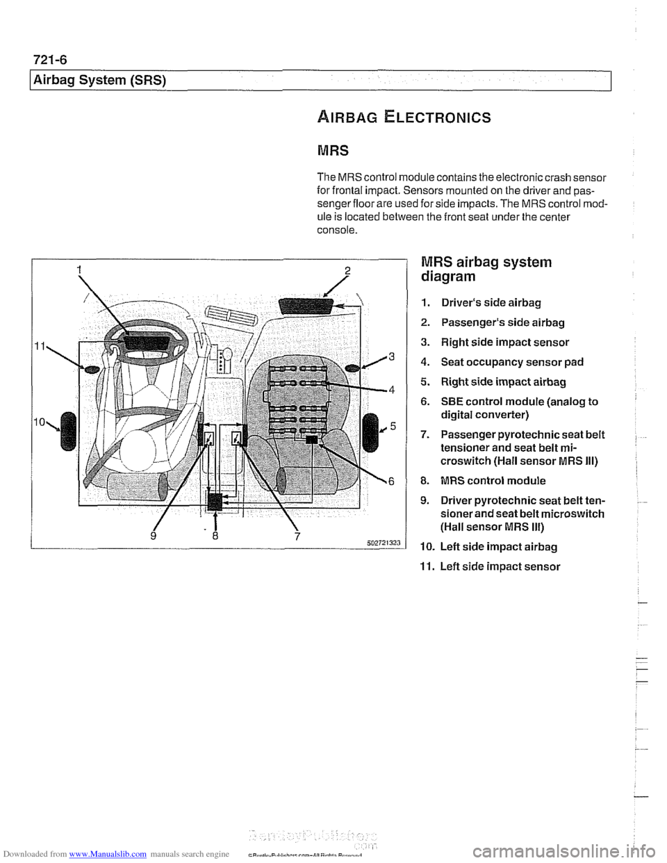
The MRS control module contains the electronic crash sensor
for frontal impact. Sensors mounted on the driver and
pas-
sengerfloor are used for side impacts. The MRS control mod-
ule
is located between the front seat under the center
console.
MRS airbag system
diagram
1. Driver's side airbag
2. Passenger's side airbag
3. Right side impact sensor
4. Seat occupancy sensor pad
5. Right side impact airbag
6. SBE control module (analog to
digital converter)
7. Passenger pyrotechnic seat belt
tensioner and seat belt
mi-
croswitch (Hall sensor MRS Ill)
8. MRS control module
9. Driver pyrotechnic seat belt ten-
sioner and seat belt microswitch
(Hall sensor MRS
Ill)
10. Left side impact airbag
11. Left side impact sensor
Page 955 of 1002
Downloaded from www.Manualslib.com manuals search engine
Airbag System (SRS)~
MRS control module, replacing
- Disconnect negative (-) cable from battery and cover nega-
tive terminal with insulating material.
CAUTIOI\C
Prior to disconnecting the battery, read the battery discon-
nection cautionsgiven in001 General Warnings and
Cau-
tions.
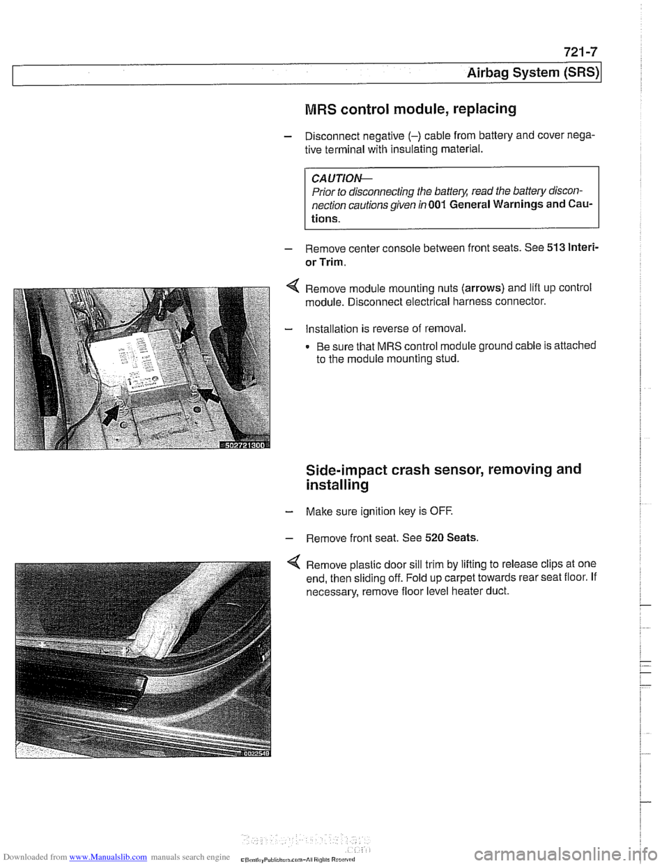
- Remove center console between front seats. See 513 lnteri-
or Trim.
Remove module mounting nuts (arrows) and lift up control
module. Disconnect electrical harness connector.
Installation is reverse of removal.
Be sure that MRS control module ground cable is attached
to the module mounting stud.
Side-impact crash sensor, removing and
installing
- Make sure ignition key is OFF.
- Remove front seat. See 520 Seats.
Remove plastic door sill trim by lifting to release clips at one
end, then sliding off. Fold up carpet towards rear seat floor. If
necessary, remove floor level heater duct.
Page 961 of 1002
Downloaded from www.Manualslib.com manuals search engine
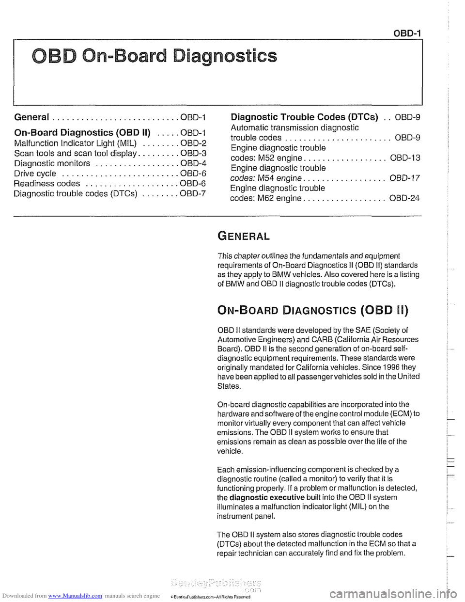
OBD On-Board Diagnostics
I I
General ........................... OBD-1 Diaqnostic Trouble Codes (DTCs) . . OBD-9
On-Board Diagnostics (OBD I!) ..... OBD-I
Malfunction Indicator Light (MIL)
........ OBD-2
Scan tools and scan tool display.
........ OBD-3
Diagnostic monitors
.................. OED-4
Drive cycle
......................... OED-6
Readiness codes
.................... OBD-6
Diagnostic trouble codes
(DTCs) ........ OBD-7
-
Automatic transmission diagnostic
trouble codes
....................... OBD-9
Engine diagnostic trouble
codes: M52 engine.
................. OED-13
Engine diagnostic trouble
codes: M54 engine.
................. OBD-17
Engine diagnostic trouble
codes: M62 engine.
................. OBD-24
This chapter outlines the fundamentals and equipment
requirements of On-Board Diagnostics
I1 (OBD 11) standards
as they apply to BMW vehicles. Also covered here is a listing
of BMW and OBD
I1 diagnostic trouble codes (DTCs).
ON-BOARD DIAGNOSTICS (QBD !I)
OBD II standards were developed by the SAE (Society of
Automotive Engineers) and CARB (California Air Resources
Board).
OED I1 is the second generation of on-board self-
diagnostic equipment requirements. These standards were
originally mandated for California vehicles. Since
1996 they
have been applied
toall passengervehicles sold in the United
States.
On-board diagnostic capabilities are incorporated into the
hardware and soflwareof the enginecontrol module
(ECM) to
monitor virtually every component that can affect vehicle
emissions. The
OED I1 system works to ensure that
emissions remain as clean as possible over the life of the
vehicle.
Each emission-influencing component is checked by a
diagnostic routine (called a monitor) to verify that it is
functioning properly.
If a problem or malfunction is detected,
the
diagnostic executive built into the OBD I1 system
illuminates a malfunction indicator light (MIL) on the
instrument panel.
The OBD
I1 system also stores diagnostic trouble codes
(DTCs) about the detected malfunction in the ECM so that a
repair technician can accurately find and fix the problem.
Page 962 of 1002
Downloaded from www.Manualslib.com manuals search engine
OED-2
On-Board Diagnostics
Specialized OED II scan tool equipment is needed to access
the fault memory and
OED I1 data.
The extra hardware needed to operate the OED
I1 system
consists mainly of the following:
* Additional oxygen sensors downstream of the catalytic
converters.
Fuel tank pressure sensor and device to pressurize
fuel
storage system.
Several engine and performance monitoring devices
Standardized 16-pin
OED II connector under the
dashboard.
Upgraded components for the federally required reliability
mandate.
Malfunction indicator light (MIL)
OED II software illuminates the malfunction indicator light
(MIL) when emission levels exceed 1.5 times Federal
standards.
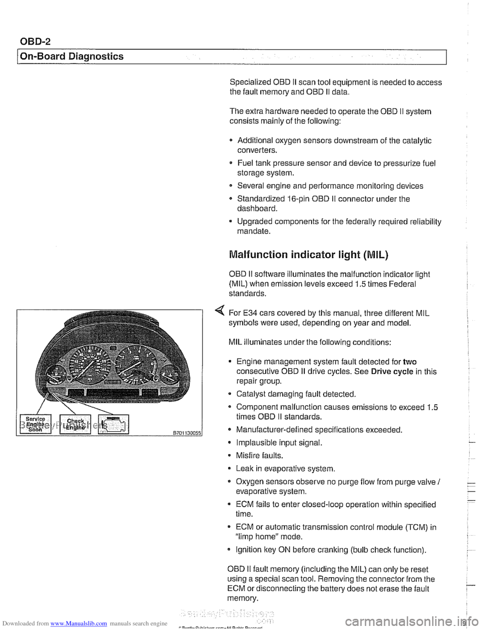
4 For E34 cars covered by this manual, three different MIL
symbols were used, depending on year and model.
MIL illuminates under the following conditions:
Engine management system fault detected for
two
consecutive OED iI drive cycles. See Drive cycle in this
repair group.
- Catalyst damaging fault detected.
Component malfunction causes emissions to exceed 1.5
times OED
II standards.
Manufacturer-defined specifications exceeded. Implausible input signal.
Misfire
faults.
Leak in evaporative system,
Oxygen sensors observe no purge
flow from purge valve 1
evaporative system.
ECM fails to enter closed-loop operation within specified
time.
ECM or automatic transmission control
module (TCM) in
"limp home" mode.
ignition key ON before cranking (bulb
check function).
OED
II fault memory (including the MIL) can only be reset
using a special scan tool. Removing the connector from the
ECM or disconnecting the battery does not erase the fault
memory.
Page 969 of 1002
Downloaded from www.Manualslib.com manuals search engine
On-Board Diagnostics
DIAGNOSTIC TROUBLE CODES
(DTCs)
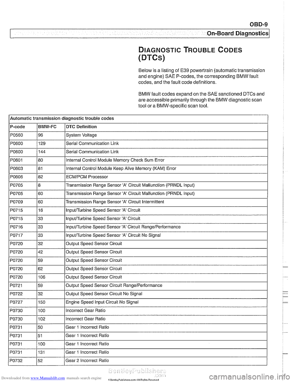
Below is a listing of E39 powertrain (automatic transmission
and engine)
SAE P-codes, the corresponding BMW fault
codes, and the fault code definitions.
BMW fault codes expand on the SAE sanctioned DTCs and
are accessible primarily through the BMW diagnostic scan
tool or a BMW-specific scan tool.
l~utomatic transmission diagnostic trouble codes
P-code
IBMW-FC I DTC Definition
Ip0560 196 ISystem Voltage I
IPO~OO I129 l~eriai Communication Link I
1~0715 116 I InpuVTurbine Speed Sensor 'A' Circuit I
PO600
PO601
PO603
PO606
PO705
PO705
PO709
144
80
81
82
8
60
60
PO71 5
PO71 6
PO717
PO720
PO720
PO720
I I
PO721 159 loutput Speed Sensor Circuit RangeIPerformance I
Serial Communication Link
Internal Control Module Memory Check Sum Error
Internal Control Module Keep Alive Memory (KAM) Error
ECMIPCM Processor
Transmission Range Sensor 'A' Circuit Maliunction (PRNDL Input)
Transmission Range Sensor
'A' Circuit Malfunction (PRNDL input)
Transmission Range Sensor
'A' Circuit Intermittent
I I'
1~0722 132 IOutput Speed Sensor Circuit No Signal I
33
33
33
32
42
59
PO720
I I
PO727 1150 I Engine Speed Input Circuit No Signal
InpuVTurbine Speed Sensor 'A' Circuit
inpuVTurbine Speed Sensor 'A' Circuit RangeiPerformance
InpuVTurbine Speed Sensor 'A' Circuit No Signal
Output Speed Sensor Circuit
Output Speed Sensor Circuit
Out~ut Speed Sensor Circuit
PO720 1106 /output Speed Sensor Circuit
62
Output Speed Sensor Circuit
PO730
PO730
PO731
PO731
PO731 I I
100
102
50
51
100
PO731
incorrect Gear Ratio
Incorrect Gear Ratio
Gear 1 incorrect Ratio
Gear 1 incorrect Ratio
Gear 1 Incorrect Ratio
PO732 152 /Gear 2 Incorrect Ratio
131
Gear
1 Incorrect Ratio
Page 971 of 1002
Downloaded from www.Manualslib.com manuals search engine
OBD-11
On-Board Diagnostics
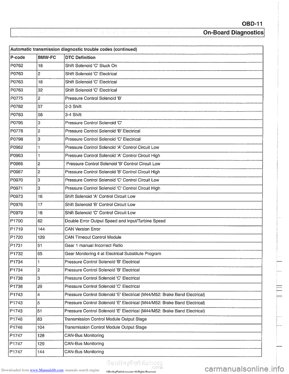
Automatic transmission diagnostic trouble codes (continued)
P-code
PO762
PO763
PO763
PO763
PO775
PO782
PO783 I I
PO795
PO798
PO962
PO963
PO966
PO967
PO970
PO971
BMW-FC
18
2 18
32
2
57
58
I I -
DTC Definition
Shift Solenoid 'C' Stuck On
Shift Solenoid
'C' Electrical
Shift Solenoid
'C' Electrical
Shift Solenoid
'C' Electrical
Pressure Control Solenoid
'B'
2-3 Shift
3-4 Shift
PO778 12 I Pressure Control Solenoid 'B' Electrical
3
3
1
1
2
2
3
3
PO973
PO979
PI 700
PI719
PI720
Pi731
PI732
PI734
Pressure Control Solenoid 'C'
Pressure Control Solenoid
'C' Electrical
Pressure Control Solenoid
'A' Control Circuit Low
Pressure Control Solenoid 'A' Control Circuit High
Pressure Control Solenoid
'6' Control Circuit Low
Pressure Control Solenoid
'0' Control Circuit High
Pressure Control Solenoid 'C' Control Circuit Low
Pressure Control Solenoid 'C' Control Circuit
High
PI734
PI738
Pi738
PO976 117 IShift Solenoid 'B' Control Circuit Low
16
18
62 144
129
51
65
1
PI743
PI743
PI743
PI746
PI746 - Pi747
Shift Solenoid 'A' Control Circuit Low
Shift Solenoid 'C' Control Circuit Low
Double Error Output Speed and
inputflurbine Speed
CAN Version Error
CAN
Timeout Control Module
Gear
1 manual Incorrect Ratio
Gear Monitoring 4 at Electrical Substitute Program
Pressure
Control Solenoid 'B' Eieclrical
2
3
29
PI747
PI747
Pressure Control Solenoid 'B' Electrical
Pressure Control Solenoid
'C' Electrical
Pressure Control Solenoid
'C' Electrical
4
5
51
83 104 Pressure Control Solenoid
'E' Electrical (M44lM52: Brake
Band Electrical)
Pressure Control Solenoid
'E' Electrical (M44lM52: Bralte Band Electrical)
Pressure Control Solenoid
'E' Electrical (M44lM52: Brake Band Electrical)
Transmission Control Module Output Stage
Transmission Control Module Output Stage
129 128 CAN-Bus Monitoring CAN-Bus Monitoring
144 CAN-Bus Monitoring
Page 972 of 1002
Downloaded from www.Manualslib.com manuals search engine
OBD-12
On-Board Diagnostics
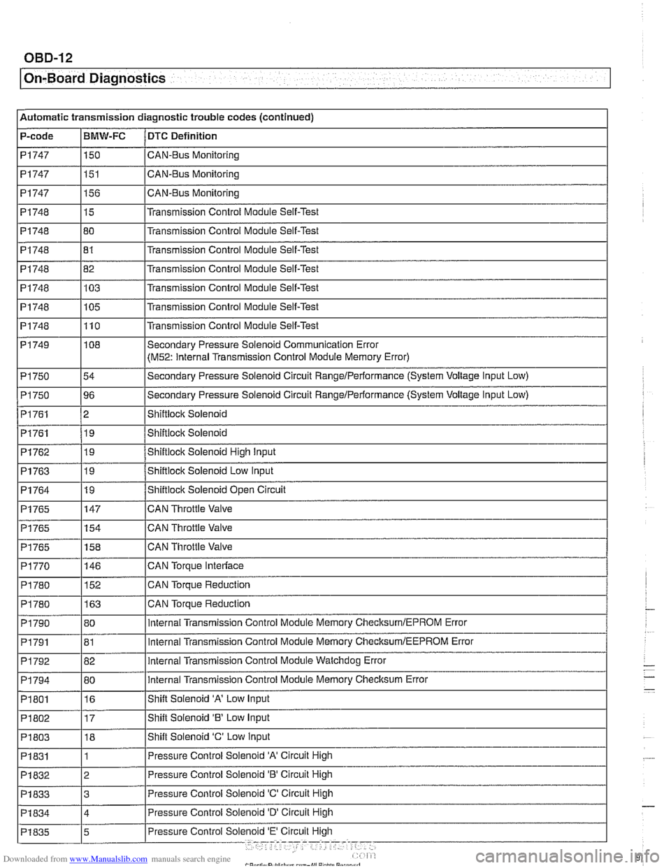
Automatic transmission diagnostic trouble codes (continued)
P-code
PI747
PI747
PI 747
PI748
PI748 I I
PI748
PI748
PI748
PI 748
PI 749
PI 750
P1750
PI761
PI761
BMW-FC
150
151
156
15
80
-- PI762
PI763
PI764
PI765
PI765
PI765
P1770
DTC Definition
CAN-BUS Monitoring
CAN-Bus Monitoring
CAN-Bus Monitoring
Transmission Control Module Self-Test
Transmission
Control Module Self-Test
PI748 182 l~ransmission Control Module Self-Test
81
103
105
110
I I
Transmission Control Module Self-Test
Transmission Control Module Self-Test
Transmission Control Module Self-Test
Transmission Control Module Self-Test
19
19
19
147
154
158
146
PI 790
PI791
P1792
PI 794
PI 801
P1802
PI 803
PI 831 Shiftiock Solenoid High input
Shiftlock Solenoid
Low Input
Shiftlock Solenoid Open Circuit
CAN Throttle Valve
CAN Throttle Valve
CAN Throttle Valve
CAN
Torpue Interlace
CAN Torque Reduction
PI 780
I I -
108
54
96
2 19
PI 780 1163 ICAN Torque Reduction
152
80
81
82
80
16
17 18
1 Secondary Pressure Solenoid Communication Error
(M52: Internal
Transmission Control Module Memory Error)
Secondary Pressure Solenoid Circuit
Rangelperformance (System Voltage Input Low)
Secondary Pressure Solenoid Circuit
RangeIPerformance (System Voltage Input Low)
Shiftioclc Solenoid
Shiftiocic Solenoid
internal Transmission Control Module Memory ChecksumlEPROM Error
internal Transmission Control Module Memory
ChecksumIEEPROM Error
internal Transmission Control Module Watchdog Error
internal Transmission Control Module Memory Checksum Error
Shift Solenoid
'A' Low Input
Shift Solenoid
'8' Low Input
Shift Solenoid
'C' Low input
Pressure Control Solenoid
'A' Circuit High
Pressure Control Solenoid 'B' Circuit High
PI832
PI833 13 IPressure Control Solenoid 'C' Circuit High
2
Page 975 of 1002
Downloaded from www.Manualslib.com manuals search engine
OBD-15
On-Board ~iagnosticsl
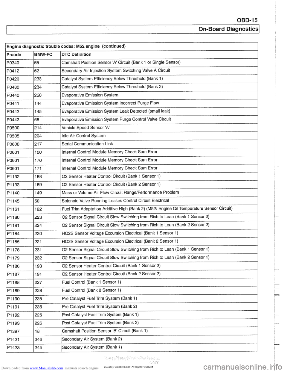
Engine diagnostic trouble codes: M52 engine (continued)
P-code
PO340
PO412
PO420
PO430
PO440
PO441
PO442
PO443
PO500
PO505
PO600
PO601
PO601
I PO601
~1132
~1133
BMW-FC
65
62
233
234
250 144
-
145
68
214
i I
DTC Definition
Camshalt Position Sensor 'A' Circuit (Bank 1 or Single Sensor)
Secondary Air Injection System Switching Valve A Circuit
Catalyst System Efficiency Below Threshold
(Bank 1)
Catalyst System Efficiency Below Threshold (Bank 2)
Evaporative Emission System
Eva~orative Emission Svstem Incorrect Purge Flow .
Evaporative Emission System Leak Detected (small leak)
Evaporative Emission System Purge Control Valve Circuit
Vehicle Speed Sensor 'A'
204
21 7
100
170
171
188
189
PI161
PI180
PI181
PI184
PI185
PI178
02 Sensor Heater Control Circuit (Bank 2 Sensor 2) I
idle Air Control System
Serial Communication
Link
Internal Control Module Memory Check Sum Error
Internal Control Module Memory
Check Sum Error
Internal Control Module Memory
Check Sum Error
02 Sensor Heater Control Circuit (Bank 1 Sensor
1)
02 Sensor Heater Control Circuit (Bank 2 Sensor 1)
Mass or Volume Air Flow Circuit RangeIPerlormance Problem PI140
I
I I
P1188 1227 I Fuel Control (Bank 1 Sensor 1)
PI145 150 /Solenoid Valve Running Losses Control Circuit Electrical
149
122
223
224
220 221
231
I I
P1189 1228 I Fuel Control (Banlc 2 Sensor 1)
Fuel Trim Adaptation Additive High (Bank 2) (M52: Engine Oil Temperature Sensor Circuit)
02 Sensor Signal Circuit Slow Switching from Rich to Lean
(Bank 1 Sensor 2)
02 Sensor Signal Circuit Slow Switching from Rich to Lean
(Bank 2 Sensor 2)
H02S Sensor Voltage Excursion Electrical (Banlc 1 Sensor 1)
HO2S Sensor Voltage Excursion Electrical (Banlc 2 Sensor 1)
02 Sensor Sianai Circuit Slow Switchina from Rich to Lean (Bank 1 Sensor 1)
02 Sensor Signal Circuit Slow Switching from Rich to Lean (Bank 2 Sensor 1) PI179
I I
PI190 1235 I Pre Catalyst Fuel Trim System (Banlc 1)
PI186 1190 102 Sensor Heater Control Circuit (Banlc 1 Sensor 2)
232
I I
PI191 1236 I Pre
Catalyst Fuel Trim System (Banlc 2)
PI192
. . -- - i Pi193 1226 I Post Catalvst Fuel Trim Svstem (Bank 2)
225
PI397
I I
Post Catalyst Fuel Trim System (Bank 1)
PI421 1246 /Secondarv Air System (Bank 2)
18
Secondary Air System (Bank
1) PI423
Camshaft Position Sensor '0' Circuit (Bank 1)
I 245