torque BMW 528i 1999 E39 User Guide
[x] Cancel search | Manufacturer: BMW, Model Year: 1999, Model line: 528i, Model: BMW 528i 1999 E39Pages: 1002
Page 46 of 1002
Downloaded from www.Manualslib.com manuals search engine
020-1 4
Maintenance
- When oil flow has diminished to an occasional drip, reinstall
drain plug with a new metal sealing washer and torque plug.
Tightening torque Engine oil drain plug to oil pan
25 Nrn (1.8 ft-lb)
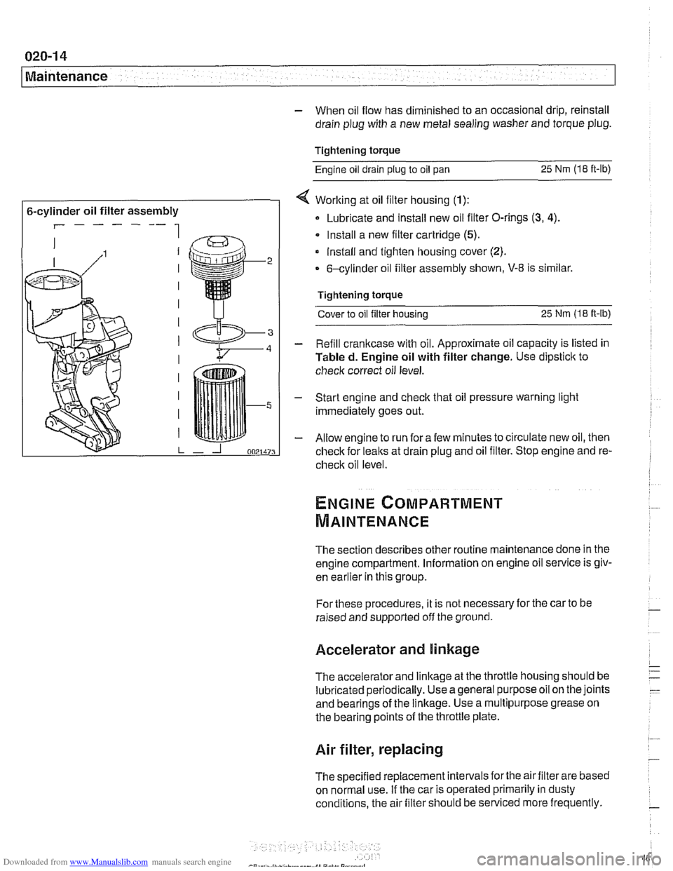
6-cylinder oil filter assembly
r------ 1
< Working at oil filter housing (1):
Lubricate and install new oil filter O-rings (3, 4).
Install a new filter cartridge (5).
lnstall and tighten housing cover (2).
6-cylinder oil filter assembly shown, V-8 is similar.
Tightening torque Cover to oil filter housing
25 Nm (1.8 it-lb)
- Refill crankcase with oil. Approximate oil capacity is listed in
Tabled. Engine oil with filter change. Use dipstick to
check correct oil level.
- Start engine and check that oil pressure warning light
immediately goes out.
- Allow engine to run fora few minutes to circulate new oil, then
check for leaks at drain plug and oil filter. Stop engine and re-
check oil level
The section describes other routine maintenance done in the
engine compartment. Information on engine oil service is
giv-
enkar~ier inthis group.
For these procedures, it is not necessary for the car to be
raised and supported off the ground.
Accelerator and linkage
The accelerator and linkage at the throttle housing should be
lubricated periodically. Use ageneral purposeoil on the joints
and bearings of the linkage. Use a multipurpose grease on
the bearing points of the throttle plate.
Air filter, replacing
The specified replacement intervals forthe air filter are based
on normal use. If the car is operated primarily in dusty
conditions, the air filter should be serviced more frequently.
Page 51 of 1002
Downloaded from www.Manualslib.com manuals search engine
Maintenance
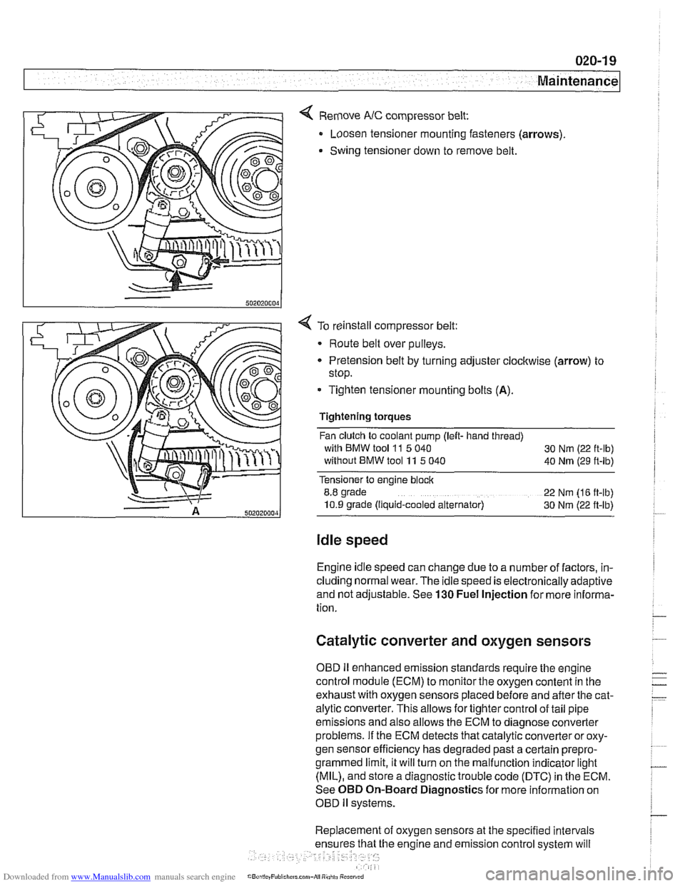
< Remove NC compressor belt:
Loosen tensioner mounting fasteners (arrows)
Swing tensioner down to remove belt.
4 To reinstall compressor belt:
Route belt over pulleys.
* Pretension belt by turning adjuster clockwise (arrow) to
stop.
- Tighten tensioner mounting bolts (A).
Tightening torques
Fan clutch to coolant pump (left- hand thread)
with BMW tool
11 5 040
30 Nm (22 ft-lb)
without BMW tool 11 5 040
40 Nm (29 ft-lb)
Tensioner to engine block
8.8 grade
22 Nm (16 ft-lb)
10.9 grade (Ilquid-cooled alternator) 30 Nm (22 ft-lb)
Idle speed
Engine idle speed can change due to a number of factors, in-
cluding normal wear. The idle speed is electronically adaptive
and not adjustable. See
130 Fuel Injection for more informa-
tion.
Catalytic converter and oxygen sensors
OBD II enhanced emission standards require the engine
control module (ECM) to monitor the oxygen content in the
exhaust with oxygen sensors placed before and after the cat-
alytic converter. This allows for tighter control of tail pipe
emissions and also allows the ECM to diagnose converter
problems. If the ECM detects that catalytic converter or oxy-
gen sensor efficiency has degraded past a certain
prepro-
grammed limit, it will turn on the malfunction indicator light
(MIL), and store a diagnostic trouble code (DTC) in the ECM.
See OBD On-Board Diagnostics for more information on
OBD
ll systems.
Replacement of oxygen sensors at the specified intervals
he engine and emission control system will
Page 52 of 1002
Downloaded from www.Manualslib.com manuals search engine
Maintenance
continue to operate as designed. Extending the replacement
interval may void the emission control warranty coverage.
See
180 Exhaust System for information on replacing the
oxygen sensors.
Tightening torque
Oxvoen sensor to exhaust
manifold 50 Nrn (37 ft-lb)
NOTE-
A special soclet for replacing the oxygen sensor is available
from most automotive parts stores. The soclet has
a groove
cut down one side to allow the sensor to be installed without
damaging the wire harness.
Power steering fluid, checking level
The power steering system is permanently filled and does not
have a drain. Routinely adding ATF is not required unless the
system is leaking.
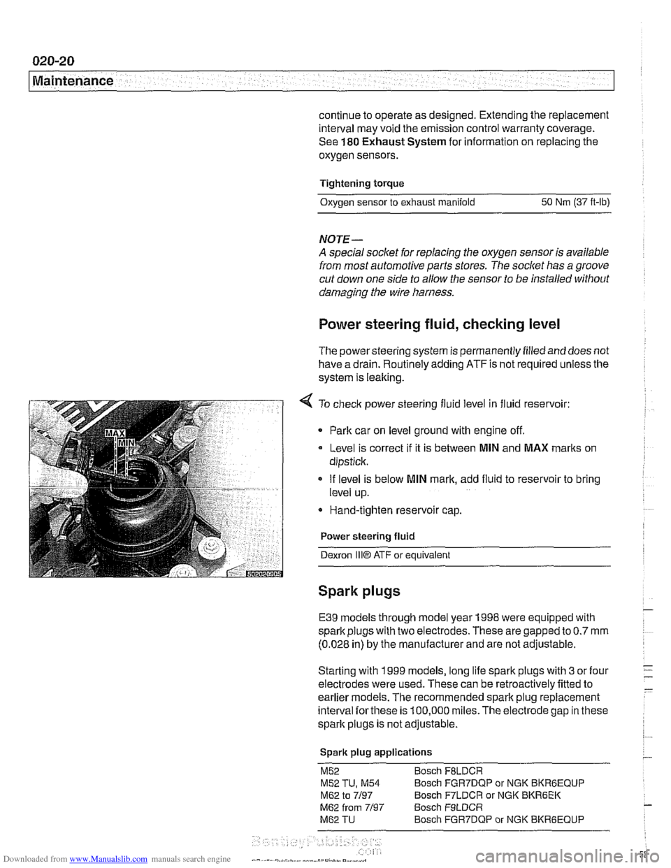
4 To check power steering fluid level in fluid reservoir:
Park car on level ground with engine off.
Level is correct
if it is between MlN and MAX marks on
dipstick.
If level is below
MlN mark, add fluid to reservoir to bring
level up.
* Hand-tighten reservoir cap.
Power steering fluid
Dexron
1iiO ATF or equivalent
Spark plugs
E39 models through model year 1998 were equipped with
spark plugs with two electrodes. These are gapped to
0.7 mm
(0.028 in) by the manufacturer and are not adjustable.
Starting with 1999 models, long life spark plugs with
3 or four
electrodes were used. These can be retroactively fitted to
earlier
models. The recommended spark plug replacement
interval
forthese is 100,000 miles.The electrode gap in these
spark plugs is not adjustable.
Spark plug applications
M52 Bosch FBLDCR
M52 TU, M54 Bosch FGR7DQP or NGK BKRBEQUP
M62 to 7/97 Bosch F7LDCR or NGK BKR6EK
M62 from 7/97 Bosch F9LDCR
M62 TU Bosch FGR7DQP or NGK BKRGEQUP
Page 54 of 1002
Downloaded from www.Manualslib.com manuals search engine
020-22 Maintenance
1
- Installation is reverse of removal, bearing in mind the
following:
Lightly lubricate new
spark plug threads with
copper-based anti-seize compound.
Thread plugs into cylinder head by hand to prevent
cross-threading.
. Be sure to reinstall and tighten coil grounds.
Tightening torque Spark plug
to cylinder head 25 Nm (18 It-lb)
Interior ventilation microfilter, replacing
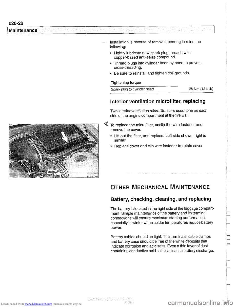
Two interior ventilation microfilters are used, one on each
side of the engine compartment at the fire wall.
< To replace the microfilter, unclip the wire fastener and
remove the cover.
Lift out the filter, and replace. Left side shown; right is
similar.
Replace cover and clip wire fastener to retain cover.
Battery, checking, cleaning, and replacing
The battery Is located in the right side of the luggage compart-
ment. Simple maintenance of the battery and its terminal
connections will ensure maximum starting periormance,
especially in winter when colder temperatures reduce battery
power.
Battery cables should be tight. The terminals, cable clamps
and battery case should be free of the white deposits that
indicate corrosion and acid salts. Even a thin layer of dust
containing conductive acid salts can cause battery discharge.
Page 58 of 1002
Downloaded from www.Manualslib.com manuals search engine
020-26
Maintenance
NOTE-
The parking brake may lose some of its effectiveness if it is
not used frequently This is due to corrosion build-up on the
parking brake drum. To remove corrosion, apply the parking
brake just until it begins to grip, then pull the lever up one
more stop (click). Drive the car approximately 400 meters
(1,300
ft.) and release the brake. To recheck the adjustment
of the parking brake see
340 Brakes.
Clutch fluid, checking
In cars equipped with manual transmission and clutch, the hy-
draulic clutch and the brake system share the same reservoir
and the same bralte fluid. Clutch fluid level and brake fluid lev-
el are checked at the same time.
NOTE-
* See 340 Brakes for more information.
See
210 Clutch for information on the clutch and the
hydraulic clutch operating system.
Differential oil level, checking
The E39 differential is filled with lifetime oil that ordinarily
does not need to be changed.
BMW recommends using only
a specially formulated synthetic gear oil
(SAF-XO) that is
available through an authorized
BM\N dealer parts depart-
ment. For additional information on this lubricant and any
other lubricants that may be compatible, contact an
authorized
BMW dealer service department.
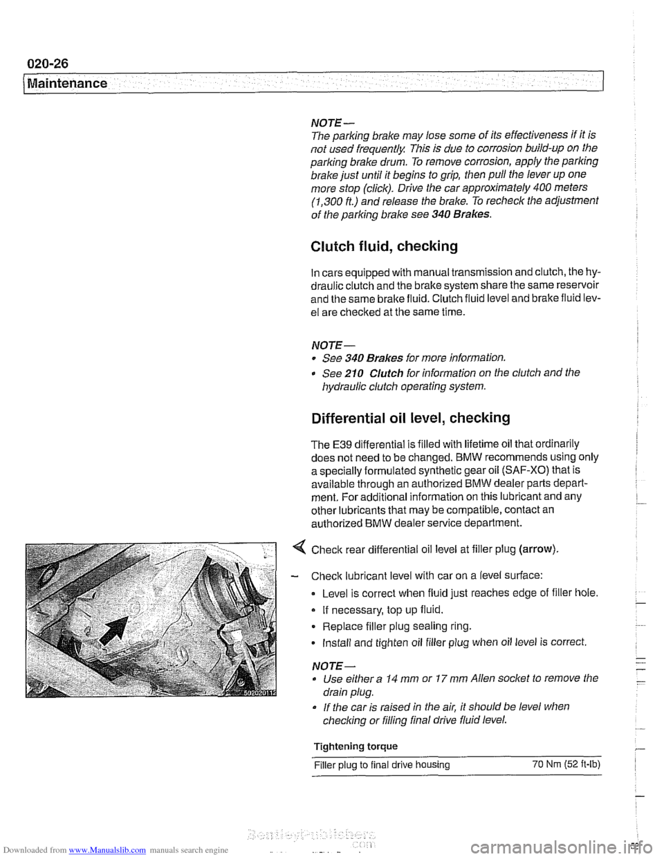
< Check rear differential oil level at filler plug (arrow).
- Check lubricant level with car on a level surface:
Level is correct when fluid just reaches edge of filler hole.
If necessary, top up fluid.
Replace filler plug sealing ring.
Install and tighten oil filler plug when oil level is correct.
NOTE-
Use either a 14 mm or 17 mm Allen socket to remove the
drain plug.
If the car is raised in the air, it should be level when
checking or filling final drive fluid level.
Tightening torque
Filler plug to final drive housing 70 Nrn (52 it-lb)
Page 87 of 1002
Downloaded from www.Manualslib.com manuals search engine
110-15
Engine Removal and lnstallation
- Installation is reverse of removal, noting the following:
Replace all gaskets. O-rings and seals.
Use new fuel injector seals
Check that engine drive belts properly engage pulley
grooves.
Inspect O-ring seal between mass air flow sensor and air
filter housing. To facilitate reassembly, coat seal with acid-
free grease.
Change engine oil and filter and
check all other fluid levels.
See
020 Maintenance.
Refill and bleed cooling system. See
170 Radiator and
Cooling System.
CAUTION--
When reattaching throttle assembly harness connectoc con-
nector is
fuNy tightened when arrows on connector and plug
line up.
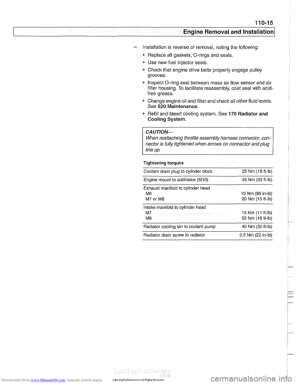
Tightening torques
Coolant drain plug to cylinder block
25 Nm (18 ft-lb)
Engine mount to
subframe (M10) 45 Nm (33 ft-ib)
Exhaust manifold to cylinder head
M6 10 Nm (89 in-lb)
M7 or ME 20 Nm (15 ft-lb)
Intake manifold to cylinder head
M7 15 Nm (I 1 ft-lb)
ME 22 Nm (16 ft-lb)
Radiator cooling fan to coolant pump
40 Nm (30 ft-lb)
Radiator drain screw to radiator
2.5 Nm (22 in-lb)
Page 89 of 1002
Downloaded from www.Manualslib.com manuals search engine
- .. -.
-. Engine Removal and in=/
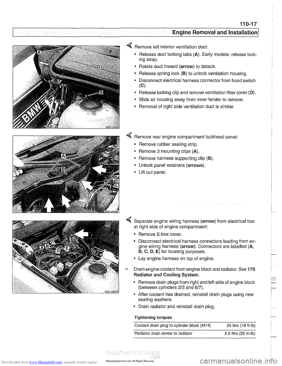
4 Remove left interior ventilation duct:
Release duct locking tabs (A). Early models: release
loclc
ing strap.
* Rotate duct inward (arrow) to detach.
Release spring
loclc (El) to unlock ventilation housing.
Disconnect electrical harness connector from hood switch
(C).
Release locking clip and remove ventilation filter cover (D).
Slide air housing away from inner fender to remove.
Removal
of right side ventilation duct is similar.
4 Remove rear engine compartment bulkhead panel:
Remove rubber sealing strip.
* Remove 3 mounting clips (A).
Remove harness supporting clip
(El).
Unlock panel retainers (arrows).
Lifl out panel.
< Separate engine wiring harness (arrow) from electrical box
at right side of engine compartment:
Remove E-box cover.
Disconnect electrical harness connectors leading from en-
gine wiring harness (arrow). Connectors are labelled (A,
El, C. D, E) for locating purposes.
Lay engine harness on top of engine.
- Drain engine coolant from engine block and radiator. See 170
Radiator and Cooling System.
Remove drain plugs from right and left side of engine
bloclc
(between cylinders 213 and 617).
Afler coolant has drained, reinstall drain plugs using new
sealing washers.
Drain radiator and reinstall drain plug.
Tightening
torques
Coolant drain plug to cylinder block (M14) 25 Nm (18 ft-ib)
Radiator drain screw to radiator 2.5
Nm (22 in-lb)
Page 94 of 1002
Downloaded from www.Manualslib.com manuals search engine
Engine Removal and Installation
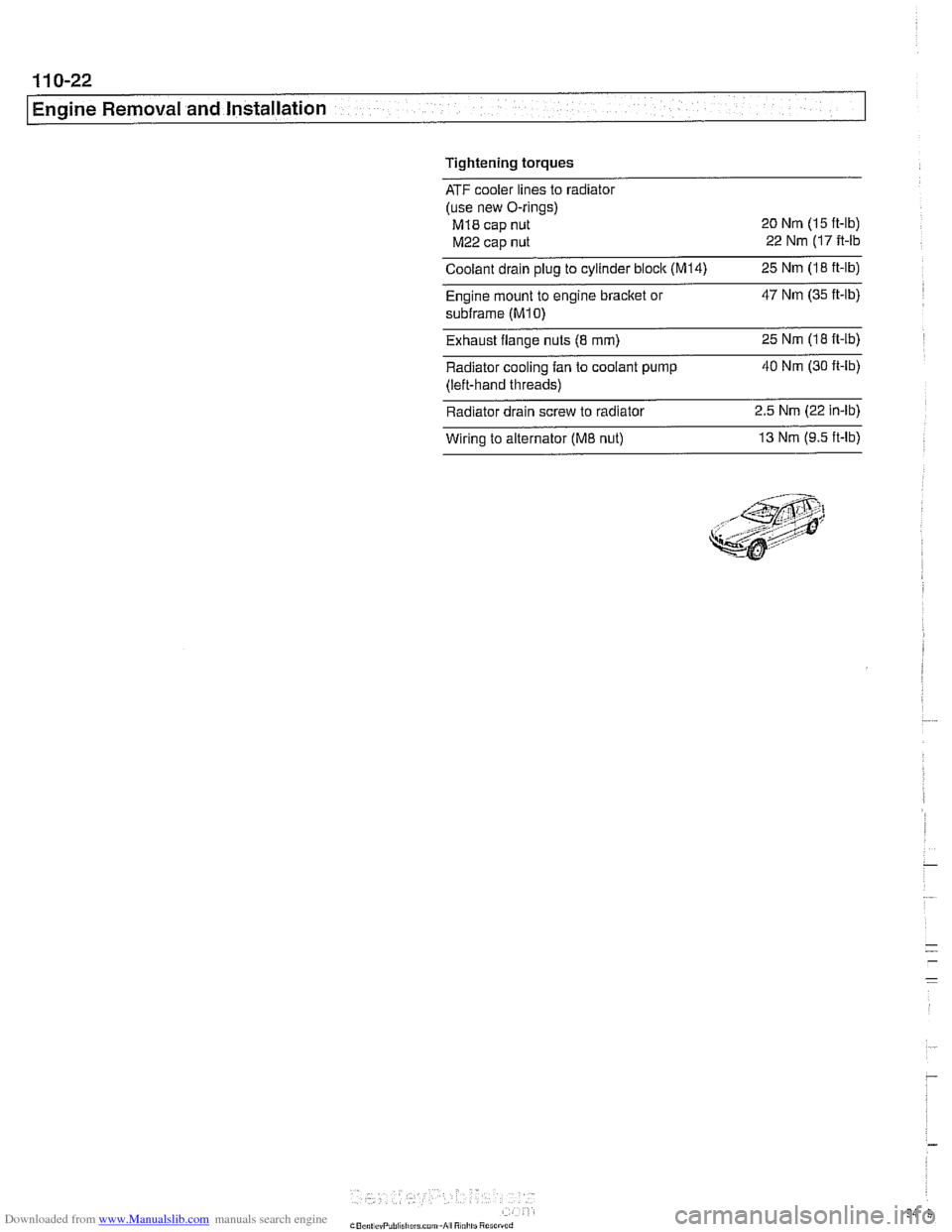
Tightening torques
ATF cooler lines to radiator
(use new O-rings)
MI8 cap nut 20 Nm (15 ft-lb)
M22 cap nut
22
Nm (17 ft-lb
Coolant drain plug to cylinder
blocic (M14) 25 Nm (18 ft-lb)
Engine mount to engine bracket or 47 Nm (35 ft-lb)
subframe (M10)
Exhaust flange nuts (8 mm) 25 Nm (18 ff-ib)
Radiator cooling fan to coolant pump 40 Nm (30 ft-lb)
(left-hand threads)
Radiator drain screw to radiator 2.5 Nm (22 in-lb)
Wirino to alternator
(ME nut) 13 Nm (9.5 ft-lb)
Page 97 of 1002
Downloaded from www.Manualslib.com manuals search engine
11 3-3
Cylinder Head Removal and Installation
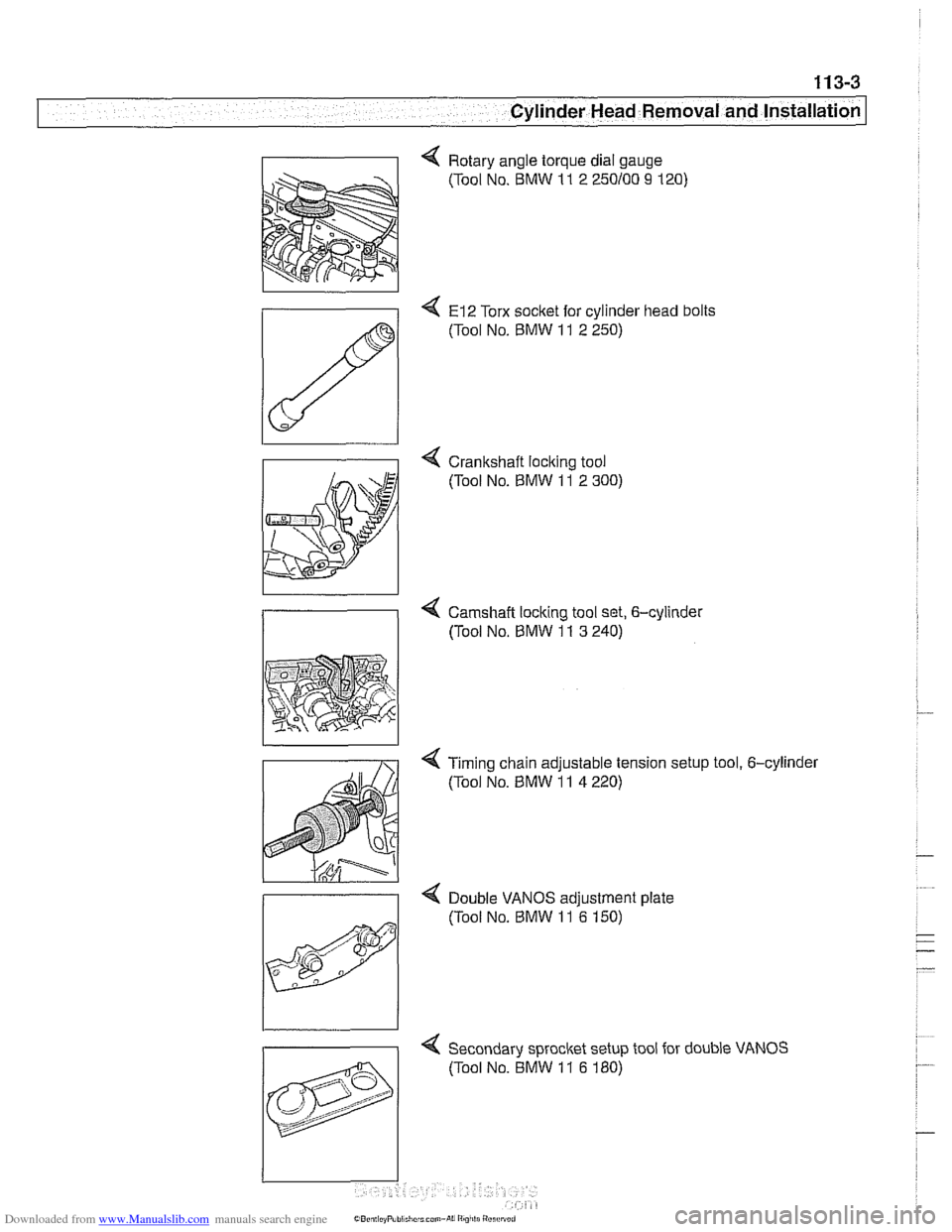
4 Rotary angle torque dial gauge
(Tool No. BMW
11 2 250100 9 120)
4 El2 Torx socket for cylinder head bolts
(Tool No.
BMW 11 2 250)
4 Crankshaft loclting tool
(Tool No.
BMW 11 2 300)
4 Camshaft locking tool set, 6-cylinder
/I (Tool No, BMW 11 3 240)
< Timing chain adjustable tension setup tool, 6-cylinder
(Tool No.
BMW 11 4 220)
>
Double VANOS adiustment date
4 Secondary sprocket setup tool for double VANOS
(Tool No. BMW
11 6 180)
Page 101 of 1002
Downloaded from www.Manualslib.com manuals search engine
. .- . --
Lr -- - - - -- Cylinder Head Removal and Installation I -
- Release pressure at compression gauge valve, then remove
gauge from spark plug hole. Repeat test for each cylinder
and compare results with values given in Table a.
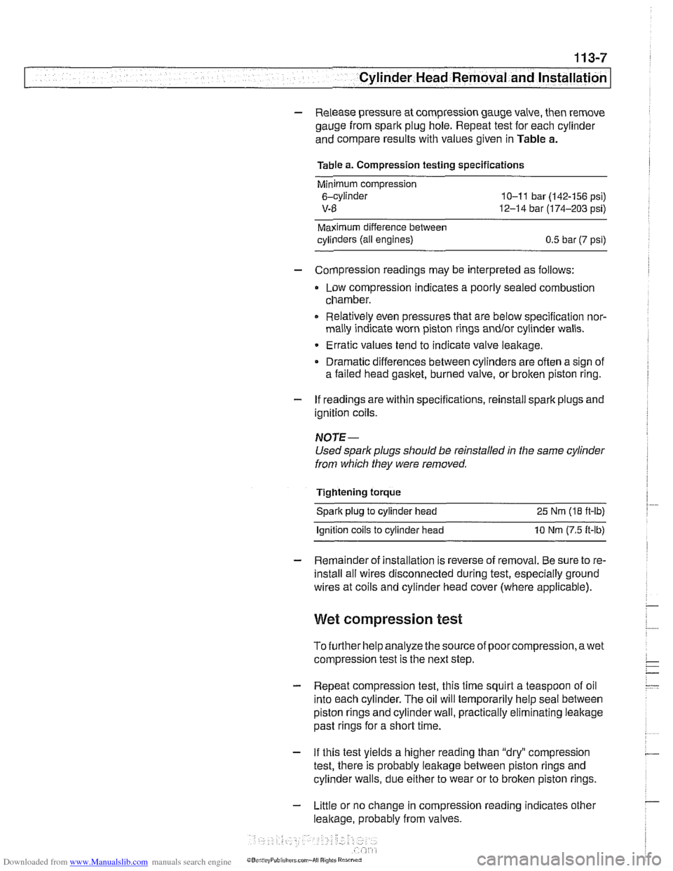
Table a. Compression testing specifications
Minimum compression
6-cylinder
10-1 1 bar (142-156 psi)
V-8 12-14 bar (174-203 psi)
Maximum difference between
cylinders (all engines)
0.5 bar (7 psi)
- Compression readings may be interpreted as follows:
Low compression indicates a poorly sealed combustion
chamber.
0 Relatively even pressures that are below specification nor-
mally indicate worn piston rings
andlor cylinder walls.
Erratic values tend to indicate valve leakage.
Dramatic differences between cylinders are often a sign of
a failed head
gasket, burned valve, or broken piston ring.
- If readings are within specifications, reinstall spark plugs and
ignition coils.
NOTE-
Used spark plugs should be reinstalled in the same cylinder
from which they were removed.
Tightening torque Spark plug to cylinder head 25 Nm
(18 ft-lb)
lanition coils to cylinder head 10 Nm (7.5 ft-lb)
- Remainder of installation is reverse of removal. Be sure to re-
install all wires disconnected during test, especially ground
wires at coils and cylinder head cover (where applicable).
Wet compression test
To further help analyze the source of poorcompression,awet
compression test is the next step.
- Repeat compression test, this time squirt a teaspoon of oil
into each cylinder. The oil will temporarily help seal between
piston rings and cylinder wall, practically eliminating leakage
past rings for a short time.
- If this test yields a higher reading than "dry" compression
test, there is probably leakage between piston rings and
cylinder walls, due either to wear or to broken piston rings.
- Little or no change in compression reading indicates other
leakage, probably from valves.