Ac control module BMW 528i 1999 E39 Repair Manual
[x] Cancel search | Manufacturer: BMW, Model Year: 1999, Model line: 528i, Model: BMW 528i 1999 E39Pages: 1002
Page 466 of 1002
Downloaded from www.Manualslib.com manuals search engine
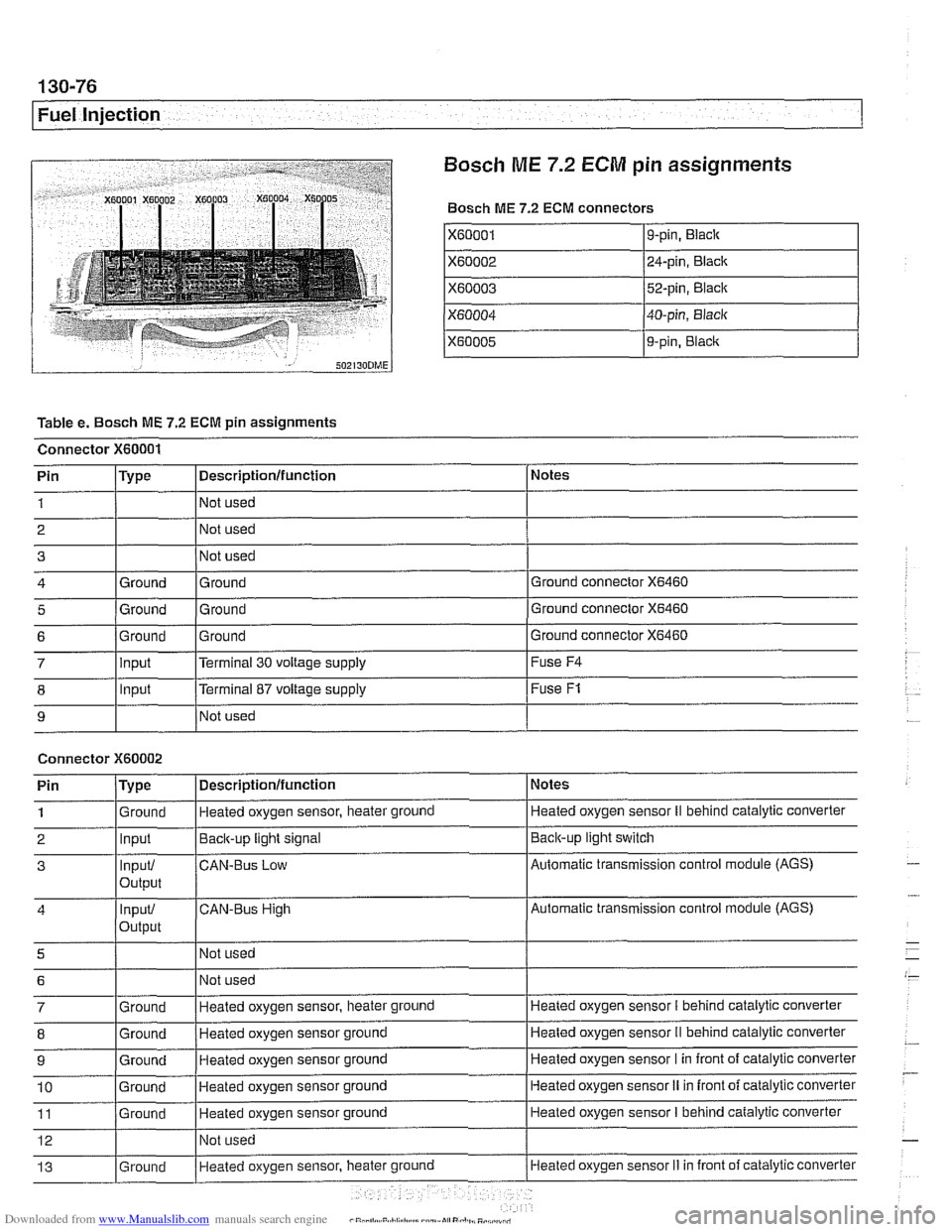
130-76
Fuel Injection
Bosch
ME 7.2 ECM pin assignments
Bosch ME 7.2 ECM connectors
X60001
X60002
X60003
X60004
X60005
Table e. Bosch ME 7.2 ECM pin assignments
Connector
X60001
I I I
8 1 lnput [Terminal 87 voltage supply I Fuse F1
9-pin, Black
24-pin, Black
52-pin, Black
40-pin, Black
9-pin,
Blaclc
I I I
9 I NO^ used I
Notes
Ground connector
X6460
Ground connector X6460
Pin 1
2 3
4
5
Connector X60002
Ground connector X6460 6
Pin
/Type I Descriptionlfunction 1 Notes
Type
Ground
Ground
7 llnput l~errninai 30 voltage supply I Fuse F4
Descriptionlfunction
Not used
Not used
Not used
Ground Ground
Ground Ground
1
2
3
4
5
6
7
8
9
10
11
12
13
. . - Ground Input
Input/
output
input/
Output
Ground
Ground
Ground
Ground
Ground
Ground Heated oxygen sensor, heater ground
Back-up
light signal
CAN-BUS Low
CAN-Bus High
Not used Not used
Heated oxygen sensor, heater ground
Heated oxygen sensor ground
Heated oxygen sensor ground
Heated oxygen sensor ground
Heated oxygen sensor ground
Not used
Heated oxvaen sensor, heater
ground
Heated oxygen sensor II behind catalylic converter
Baclcup light switch
Automatic transmission control module (AGS)
Automatic transmission control module (AGS)
Heated oxygen sensor
I behind catalytic converter
Heated oxygen sensor
II behind catalytic converter
Heated oxygen sensor I in front of catalytic converter
Heated oxygen sensor
II in front of catalytic converter
Heated oxygen sensor
I behind catalytic converter
Heated oxygen sensor
Ii in front of catalytic converter
Page 467 of 1002
Downloaded from www.Manualslib.com manuals search engine
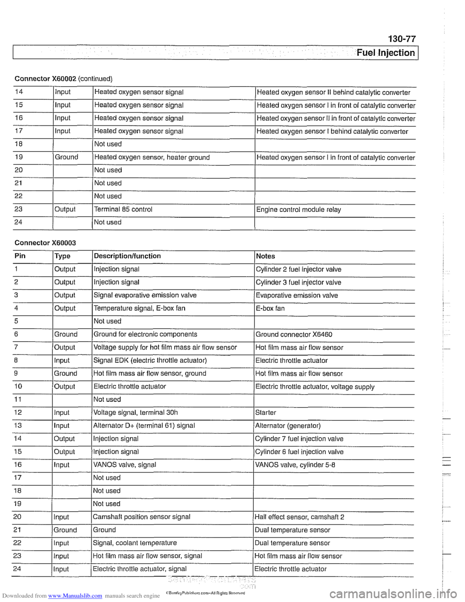
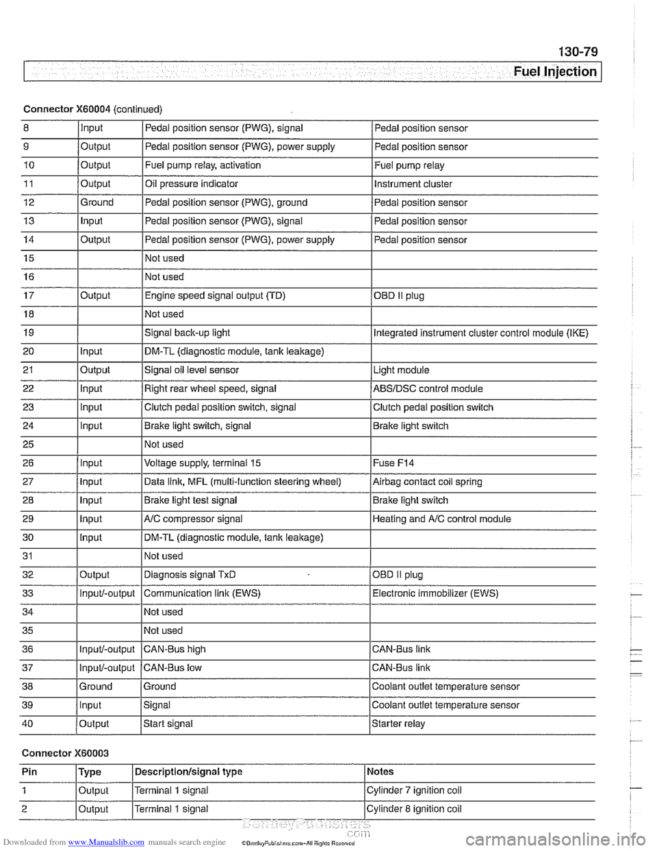
Fuel lnjection
I 1- I
4 /output l~em~erature signal. E-box fan I E-box fan
Connector
X60002 (continued)
14
15
16
17
18
19
20
21
22
23
24
5
6
7
8
9
10
11
12
13
14
15
16
Input
Input
Input
Input
Ground
Output Heated
oxygen sensor signal
Heated oxygen sensor signal
Heated oxygen sensor signal
Heated oxygen sensor signal
Not used
Heated oxygen sensor, heater ground
Not used
Not used
Not used
Terminal 85 control
Not used Heated oxygen sensor
II behind catalytic converter
Heated oxygen sensor
I in front of catalytic converter
Heated oxygen sensor
I1 in front of catalytic converter
Heated oxygen sensor
I behind catalytic converter
Heated oxygen sensor I in front of catalytic converter
Engine control module relay
Connector
X60003
Ground
Output Input
Ground
Output
Input
Input
Output
Output
Input
Pin 1
2
3
Not used
Ground for electronic components
Voltage supply for hot
film mass air flow sensor
Signal EDK (electric throttle actuator) Hot film mass air flow sensor, ground
Electric throttle actuator
Not used
Voltage signal, terminal 30h
Alternator
D+ (terminal 61) signal
Injection signal
Injection signal
VANOS valve, signal
Type
Output
Output
Output
Ground connector
X6460
Hot film mass air flow sensor
Electric throttle actuator
Hot film mass air flow sensor
Electric throttle actuator, voltage supply
Starter
Alternator (generator)
Cylinder
7 fuel injection valve
Cylinder 6 fuel injection valve
VANOS valve, cylinder
5-8
Descriptionlfunction
Injection signal
Injection signal
Signal evaporative emission valve Notes
Cylinder 2 fuel injector valve
Cylinder 3 fuel injector valve
Evaporative emission valve
Page 469 of 1002
Downloaded from www.Manualslib.com manuals search engine
Fuel Injection I
Connector X60004 (continued)
8 10
11
12
13
14
15
16
9
Output 0
Input
17
18
19
20
21
22
23
24
25
26
27
28
29
30
31
32
33
34
35
36
39
llnput lsignal l~oolant outlet temperature sensor
Output
Output
Ground
Input
Output
I I - I
40 /output Istart signal Istarter relay
Pedal position sensor (PWG), signal
Output Input
Output
input
Input
Input
Input
Input
Input
input
Input
Output
Input/-output
Input/-output
37
Connector X60003
Pedal position sensor
Fuel pump relay, activation
Oil pressure indicator Pedal position sensor (PWG), ground
Pedal position sensor (PWG), signal
Pedal position sensor (PWG), power supply
Not used
Not used Fuel
pump relay
Instrument cluster
Pedal position sensor
Pedal position sensor
Pedal position sensor
Engine speed signal output (TD)
Not used
Signal
back-up light
DM-TL (diagnostic module,
tank leakage)
Signal oil level sensor
Right rear wheel speed, signal
Clutch pedal position switch, signal
Brake light switch, signal
Not used
Voltage supply, terminal
15
Data link, MFL (multi-function steering wheel)
Brake light test signal
AJC compressor signal
DM-TL (diagnostic module, tank
leakage)
Not used
Diagnosis signal
TxD
Communication link (EWS)
Not used
Not used
CAN-BUS hiqh
38 1 Ground l~round I Coolant outlet temperature sensor
OED II plug
Integrated instrument cluster control module (IKE)
Light module
ABSIDSC control module
Clutch pedal position switch
Brake light switch
Fuse
F14
Airbag contact coil spring
Brake light switch
Heating and
A/C control module
OBD
II plug
Electronic immobilizer (EWS)
CAN-Bus link
CAN-Bus link
Input/-output CAN-Bus low
Page 473 of 1002
Downloaded from www.Manualslib.com manuals search engine
Fuel Tank and Fuel Pump
Fuel pump
The electric fuel pump is mounted in the fuel tank in tandem
with the right side fuel level sender. The fuel pump delivers
pressurized fuel to the fuel injection system.
A pressure regu-
lator maintains system pressure. The quantity of fuel supplied
exceeds demand, so excess fuel returns to the fuel tank via a
return line. See
130 Fuel Injection for more information.
NOTE-
Fuel pump removal procedures are given under Fuel level
sender (right side) and fuel pump, removing and install-
ing.
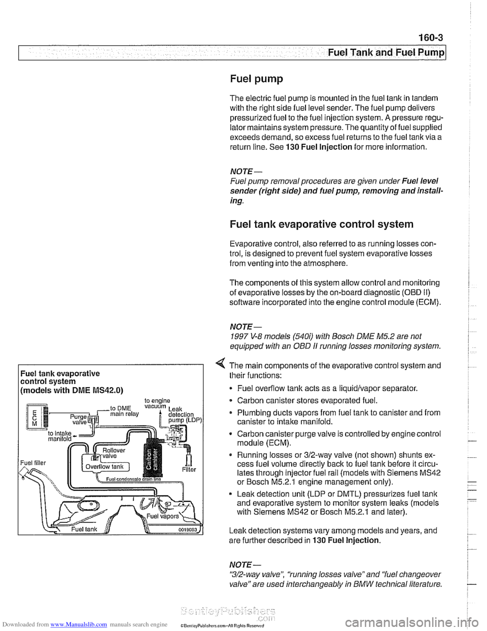
Fuel tank evaporative control system
Evaporative control, also referred to as running losses con-
trol, is designed to prevent fuel system evaporative losses
from venting into the atmosphere.
The components of this system allow control and monitoring
of evaporative losses by the on-board diagnostic
(OED II)
software incorporated into the engine control module (ECM).
NOTE-
1997 V-8 models (540i) with Bosch DME M5.2 are not
equipped with an
OBD I1 running losses monitoring system.
Fuel tank evaporative
control system
(models with
DME MS42.0)
4 The main components of the evaporative control system and
their functions:
Fuel overflow
tank acts as a liquidlvapor separator
Carbon canister stores evaporated fuel.
Plumbing ducts vapors from fuel tank to canister and from
canister to intake
manifold.
- Carbon canister purge valve is controlled by enginecontrol
module (ECM).
Running losses or 312-way valve (not shown) shunts ex-
cess fuel volume directly
back to fuel tank before it circu-
lates through injector fuel rail (models with Siemens MS42
or Bosch M5.2.1 engine management only).
Leak detection unit (LDP or DMTL) pressurizes fuel
tank
and evaporative system to monitor system leaks (models
with Siemens MS42 or Bosch M5.2.1 and later).
Leak detection systems vary among models and years, and
are further described in
130 Fuel Injection.
NOTE -
"3/2-way valve", 'tunning losses valve" and "fuel changeover
valve" are used interchangeably
in BMW technical literature.
Page 475 of 1002
Downloaded from www.Manualslib.com manuals search engine
Fuel Tank and Fuel Pump
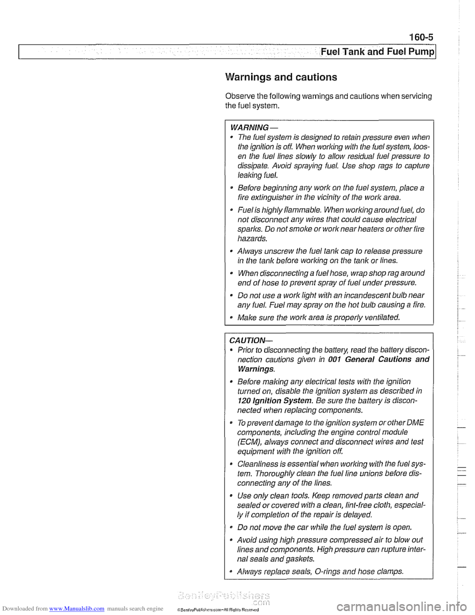
Warnings and cautions
Observe the following warnings and cautions when servicing
the fuel system.
WARNING-
* The fuel system is designed to retain pressure even when
the ignition is off. When working with the fuelsystem, loos-
en the fuel lines slowly to allow residual
fuel pressure to
dissipate. Avoid spraying fuel. Use shop rags to capture
leaking fuel.
Before beginning any work on the fuel system, place a
fire extinguisher in the vicinity of the work area.
Fuel is highly flammable. When working around fuel, do
not disconnect any wires that could cause electrical
sparks. Do not smoke or worknearheaters or other fire
hazards.
* Always unscrew the fuel tank cap to release pressure
in the
tanlc before working on the tank or lines.
When disconnecting a fuel hose, wrap shop rag around
end of hose to prevent spray of fuel under pressure.
Do not use a work light with an incandescent bulb near
any fuel. Fuel may spray on the hot bulb causing a fire.
0 Make sure the worlc area is properly ventilated.
CAUTION-
- Prior to disconnecting the battery, read the battery discon-
nection cautions given in
001 General Cautions an4
Warnings.
Before
making any electrical tests with the ignition
turned on, disable the ignition system as described in
120 Ignition System. Be sure the battery is discon-
nected when replacing components.
To prevent damage to the ignition system or other DME
components, including the engine control module
(ECM), always connect and disconnect wires and test
equipment with the ignition off.
Cleanliness is essential when
worl~ing with the fuel sys-
tem. Thoroughly clean the fuel line unions before dis-
connecting any of the lines.
Use only clean tools. Keep removed parts clean and
sealed or covered with a clean, lint-free cloth, especial-
ly if completion of the repair is delayed.
Do not move the car while the fuel system is open.
Avoid using high pressure compressed air to blow out
lines and components. High pressure can rupture inter-
nal seals and gaskets.
Always replace seals, O-rings and hose clamps.
Page 476 of 1002
Downloaded from www.Manualslib.com manuals search engine
.-- -
/ Fuel Tank and Fuel Pump - .. -. -- 1
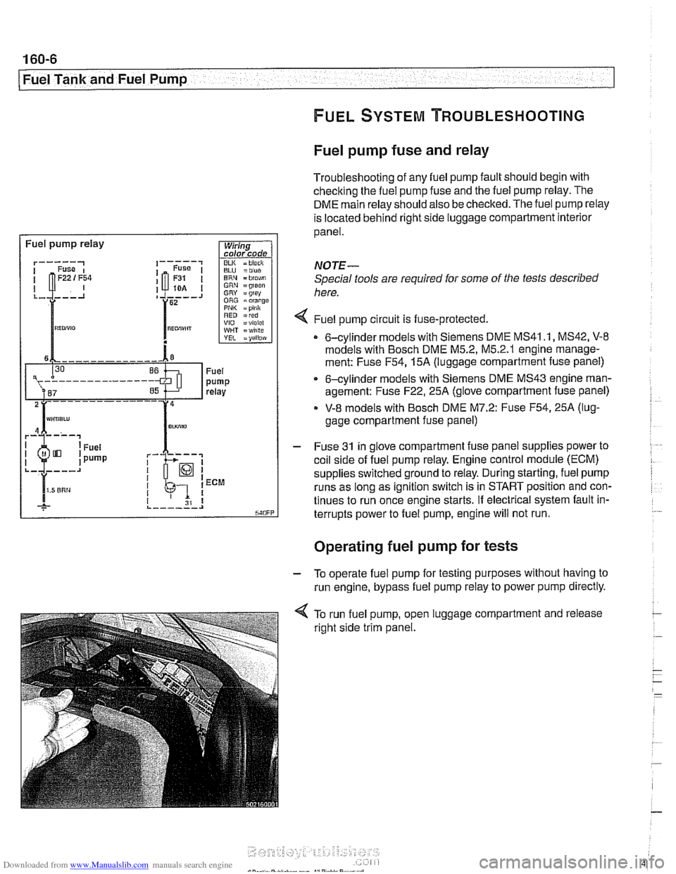
Fuel pump fuse and relay
Troubleshooting of any fuel pump fault should begin with
checking the fuel pump fuse and the fuel pump relay. The
DME main relay should also be checked. The fuel pump relay
is located behind right side luggage compartment interior
panel.
I Fuel pump relay
BLU =blue ERN = blo$,m GRN =groan GRY = grsy ORG =orange PNI< =pink RED =red VIO =violel WHT = wlilte
rk-; I I 1 ECM
I I I 31 8 ,._--___.I
NOTE-
Special tools are required for some of the tests described
here.
4 Fuel pump circu~t is fuse-protected.
0 6-cylinder models with Siemens DME MS41 .I, MS42, V-8
models with Bosch DME M5.2, M5.2.1 englne manage-
ment: Fuse
F54,15A (luggage compartment fuse panel)
6-cylinder models with Siemens DME MS43 engine man-
agement: Fuse
F22,25A (glove compartment fuse panel)
V-8 models with Bosch DME M7.2: Fuse F54,25A (lug-
gage compartment fuse panel)
- Fuse 31 in glove compartment fuse panel supplies power to
coil side of fuel pump relay. Engine control module (ECM)
supplies switched ground to relay. During starting, fuel pump
runs as long as ignition switch is in START position and con-
tinues to run once engine starts. If electrical system fault in-
terrupts power to fuel pump, engine will not run.
. .
Operating fuel pump for tests
- To operate fuel pump for testing purposes without having to
run engine, bypass fuel pump relay to power pump directly.
< To run fuel pump, open luggage compartment and release
right side trim panel.
Page 494 of 1002
Downloaded from www.Manualslib.com manuals search engine
Fuel Tank and Fuel Pump 1
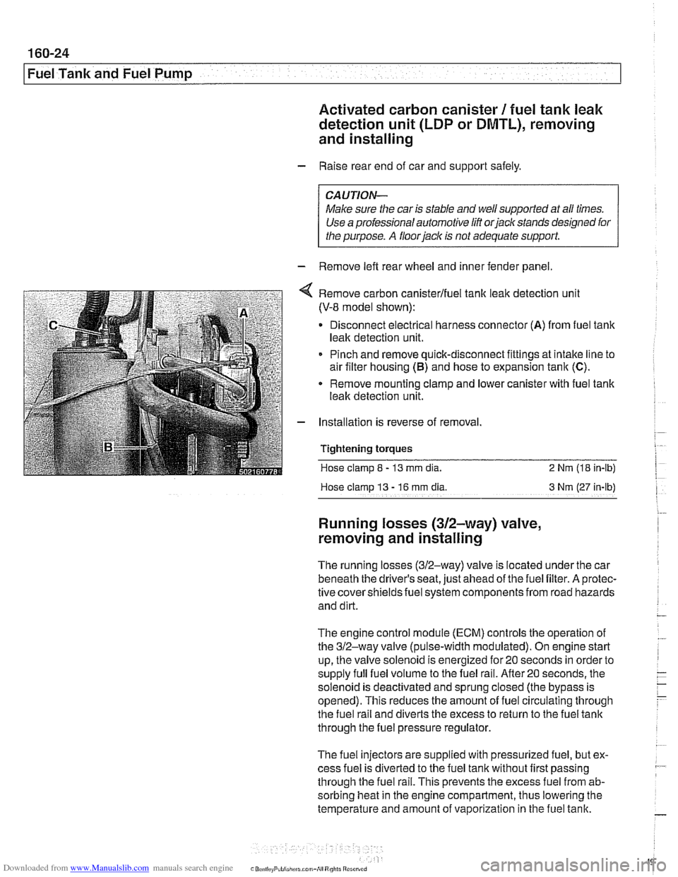
Activated carbon canister I fuel tank leak
detection unit
(LDP or DMTL), removing . . -
and installing
- Raise rear end of car and support safely.
CAUTION-
Make sure the car is stable and well supported at all times.
Use a professional automotive lift
orjack stands designed for
the purpose.
A floor jack is not adequate support.
- Remove left rear wheel and inner fender panel
Remove carbon canisterlfuel tank leak detection unit
(V-8 model shown):
Disconnect electrical harness connector
(A) from fuel tank
leak detection unit.
Pinch and remove quick-disconnect fittings at intake line to
air filter housing
(5) and hose to expansion tank (C).
* Remove mounting clamp and lower canister with fuel tank
leak detection unit.
Installation is reverse of removal.
Tightening
torques
Hose clamp 8 - 13 mm dia. 2 Nrn (18 in-lb)
Hose clamp
13 - 16 rnm dia 3 Nm (27 in-lb)
Running losses (312-way) valve,
removing and installing
The running losses (312-way) valve is located under the car
beneath the driver's seat, just ahead of the fuel filter. A protec-
tive covershieldsfuel system components from road hazards
and dirt.
The engine control module
(ECM) controls the operation of
the 312-way valve (pulse-width modulated). On engine start
up, the valve solenoid is energized for 20 seconds in order to
supply full fuel volume to the fuel rail.
After20 seconds, the
solenoid is deactivated and sprung closed (the bypass is
opened). This reduces the amount of fuel circulating through
the fuel rail and diverts the excess to return to the fuel tank
through the fuel pressure regulator.
The fuel injectors are supplied with pressurized fuel, but ex-
cess fuel is diverted to the fuel tank without first passing
through the fuel rail. This prevents the excess fuel from ab-
sorbing heat in the engine compartment, thus lowering the
temperature and amount of vaporization in the fuel tank.
Page 500 of 1002
Downloaded from www.Manualslib.com manuals search engine
-
I Radiator and Cooling System
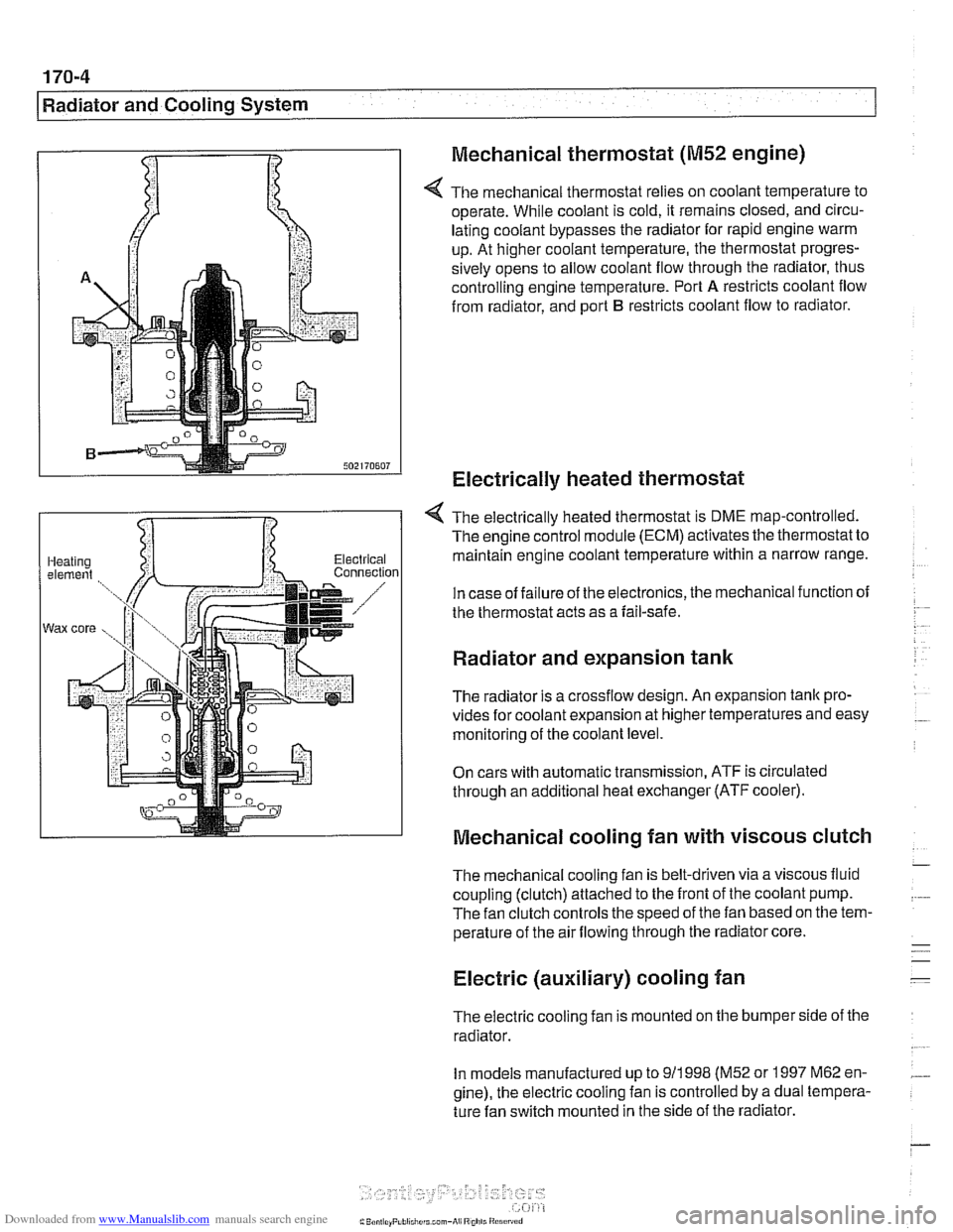
Mechanical thermostat
(M52 engine)
4 The mechanical thermostat relies on coolant temperature to
operate. While coolant is cold, it remains closed, and circu-
lating coolant bypasses the radiator for rapid engine warm
up. At higher coolant temperature, the thermostat progres-
sively opens to allow coolant flow through the radiator, thus
controlling engine temperature. Port
A restricts coolant flow
from radiator, and port
B restricts coolant flow to radiator.
Electrically heated thermostat
4 The electrically heated thermostat is DME map-controlled.
The engine control module (ECM) activates the thermostat to
maintain engine coolant temperature within a narrow range.
In case of failure of the electronics, the mechanical function of
the thermostat acts as a fail-safe.
Radiator and expansion tank
The radiator is a crossflow design. An expansion tank pro-
vides for coolant expansion at higher temperatures and easy
monitoring of the coolant level.
On cars with automatic transmission, ATF is circulated
through an additional heat exchanger (ATF cooler).
Mechanical cooling fan with viscous clutch
The mechanical cooling fan is belt-driven via a viscous fluid
coupling (clutch) attached to the front of the coolant pump.
The fan clutch controls the speed of the fan based on the tem-
perature of the air flowing through the radiator core.
Electric (auxiliary) cooling fan
The electric cooling fan is mounted on the bumper side of the
radiator.
In models manufactured up to
911 998 (M52 or 1997 M62 en-
gine), the electric cooling fan is controlled by a dual tempera-
ture fan switch mounted in the side of the radiator.
Page 501 of 1002
Downloaded from www.Manualslib.com manuals search engine
170-5
Radiator and Cooling System
Fan switch calibration (M52, M62 engine)
coniprairoi OUt rlgnal
Auto. ciimilte ~ontioi inpuls via CAN bus
Electric fan activation:
Low speed
91°C (196°F)
High speed 104' C (21 9' F)
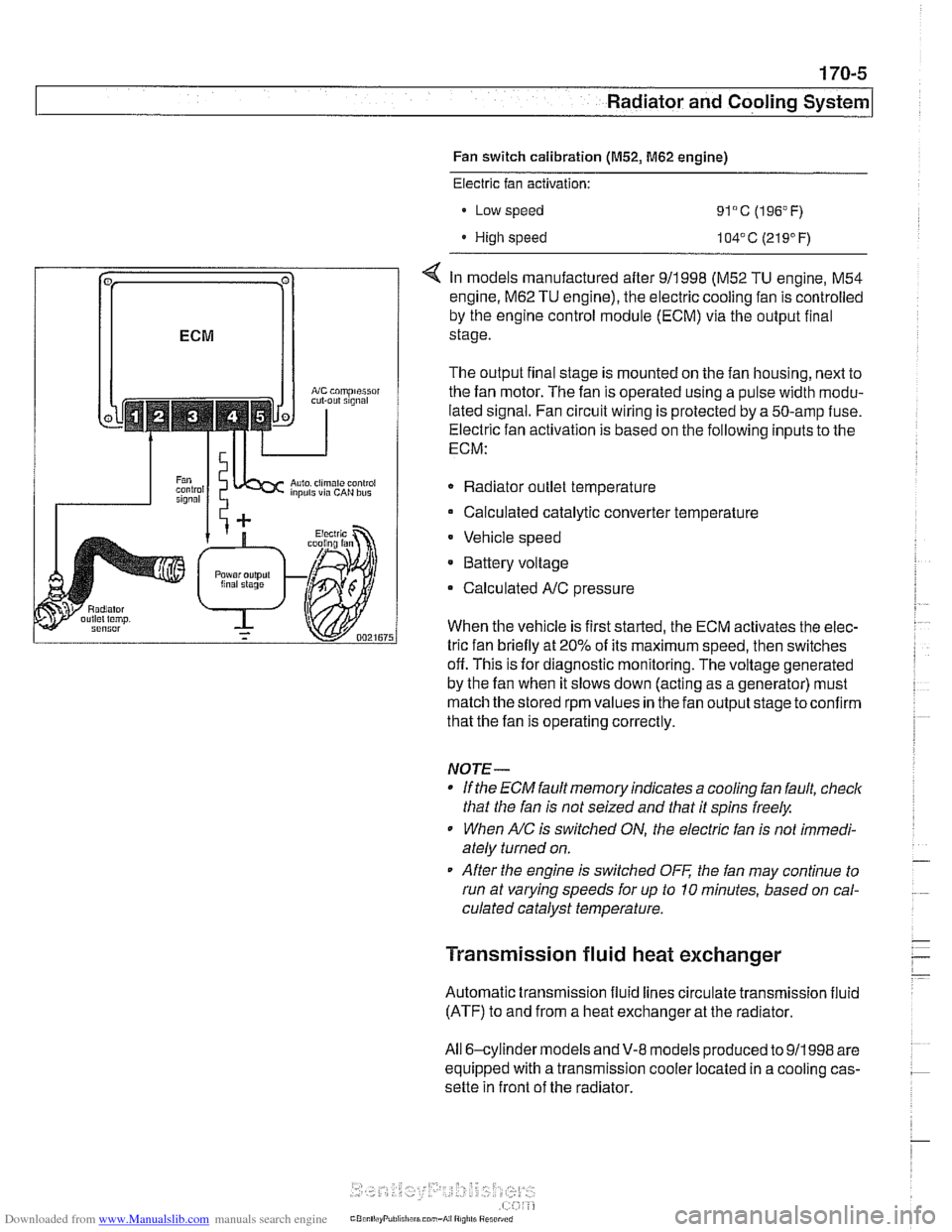
< In models manufactured after 911998 (M52 TU engine, M54
engine.
M62 TU engine), the electric cooling fan is controlled
by the engine control module (ECM) via the output final
stage.
The output final stage is mounted on the fan housing, next to
the fan motor. The fan is operated using a pulse width modu-
lated signal. Fan circuit wiring is protected by a 50-amp fuse.
Electric fan activation is based on the following inputs to the
ECM:
Radiator outlet temperature
Calculated catalytic converter temperature
Vehicle speed
* Battery voltage
Calculated
A/C pressure
When the vehicle is first started, the ECM activates the elec-
tric fan briefly at 20% of its maximum speed, then switches
off. This is for diagnostic monitoring. The voltage generated
by the fan when it slows down (acting as a generator) must
match the stored rpm values in the fan output stage toconfirm
that the fan is operating correctly.
NOTE-
If the ECM fault memory indicates a cooling fan fault, check
that the fan is not seized and that it spins freely.
When
A/C is switched ON, the electric fan is not immedi-
ately turned on.
After the engine is switched
OFF the fan may continue to
run at varying speeds for up to 10 minutes, based on cal-
culated catalyst temperature.
Transmission fluid heat exchanger
Automatic transmission fluid lines circulate transmission fluid
(ATF) to and from a heat exchanger at the radiator.
All 6-cylinder
models andV-8 models produced to 911998 are
equipped with a transmission cooler located in a cooling cas-
sette in front of the radiator.
Page 503 of 1002
Downloaded from www.Manualslib.com manuals search engine
Warnings and cautions
Obse~e the following warnings and cautions when worlting
on the cooling system.
WARNING -
. At normal operating temperature the cooling system is
pressurized. Allow the system to cool as long as possible
before opening (a minimum of one hour), then release the
cap slowly to allow safe release ofpressure.
a Releasing the coolant system pressure lowers the cool-
ant boilingpoint and the coolant may boil suddenly. Use
1 heavy and wear eye and face protection to
guard against scalding.
Use extreme care when draining and disposing of en-
gine coolant. Coolant is poisonous and lethal to hu-
mans andpets. Pets are attracted to coolant because
of its sweet smell and taste. Seek medical attention im-
mediately if coolant is ingested.
CAUTIOG
Avoid adding cold water to the coolant while the engine is
hot or overheated. If it is necessary to add coolant to a
hol
system, do so only with the engine running and coolanl
pump turning.
To avoid excess silicate gel precipitation in the cooling
system and loss of cooling capacity, use BMW coolant
or equivalent low silicate antifreeze.
a If oil enters the cooling system, the radiator, expansion
tank and heating circuit must be flushed with cleaning
agent. BMW recommends removal of the radiator and
expansion
tank to flush.
When
worlcing on the cooling system, cover the alter-
nator to protect it against coolant drips.
Prior to disconnecting the battery, read the battery dis-
connection cautions given in
001 General Warnings
and Cautions.
Begin the diagnosis of cooling system problems with a thor-
ough visual inspection.
If no visual faults are found, it is rec-
ommend that the engine control module (ECM) fault memory
be checked for stored diagnostic trouble codes
(DTCs) using
BMW scan tool
DlSplus or equivalent.