130 BMW 528i 1999 E39 Workshop Manual
[x] Cancel search | Manufacturer: BMW, Model Year: 1999, Model line: 528i, Model: BMW 528i 1999 E39Pages: 1002
Page 3 of 1002

Downloaded from www.Manualslib.com manuals search engine
YOU are now in Volume I
I
Foreword ................... .. ........................................................................\
.......... v
Index
........................ .. ................................................................ rear of manual
General, 001 General Warnings and Cautions 002 Vehicle Identification and VIN Decoder
Maintenance OiO 020 Maintenance
Engine
100 Engine-General 110 Engine Removal and Installation
113 Cylinder Head Removal and
Installation
116 Cyiinder Head and Valvetrain 117 Camshaft Timing Chain
119 Lubrication System
200 Transmission-General
2 Transmission 210 clutch 230 ManualTransmission
I20 Ignition System
121 Battery, Starter, Alternator
130 Fuel Injection
160 Fuel Tank and Fuel Pump 170 Radiator and Cooling System
180 Exhaust System
240 Automatic Transmission
250 Gearshift Linkage 260 Driveshaft
Suspension, 300 Suspension, Steering and 330 Rear Suspension
Brakes-General 331 Final Drive
Steering and No Front Suspension 340 Brakes
320 Steering and Wheel Alignment
400 Body-General
410 Fenders, Engine Hood 411 Doors
412 Trunk Lid, Tailgate
510 Exterior Trim, Bumpers 512 Door Windows
Equipment 513 Interior Trim
7
Equipment and 720 seat Belts
Accessories 721 Airbag System (SRS)
OBD On-Board Diagnostics
. ............ ..
515 Central Lociting and
Anti-Theft
520 Seats 540 Sunroof
.................................................................... Foreword .............................. .. v
Index ................... .. ................................................................ rear of manual
Electrical
6 system
600 Electrical System-General 620 Instruments
610 Electrical Comoonent Locations 630 Liohts
611 wipers and washers 612 Switches eati in^ and Air Conditioning
Radio
. ........... ........ .........................
Electrical Wiring Diagrams
Page 39 of 1002
Downloaded from www.Manualslib.com manuals search engine
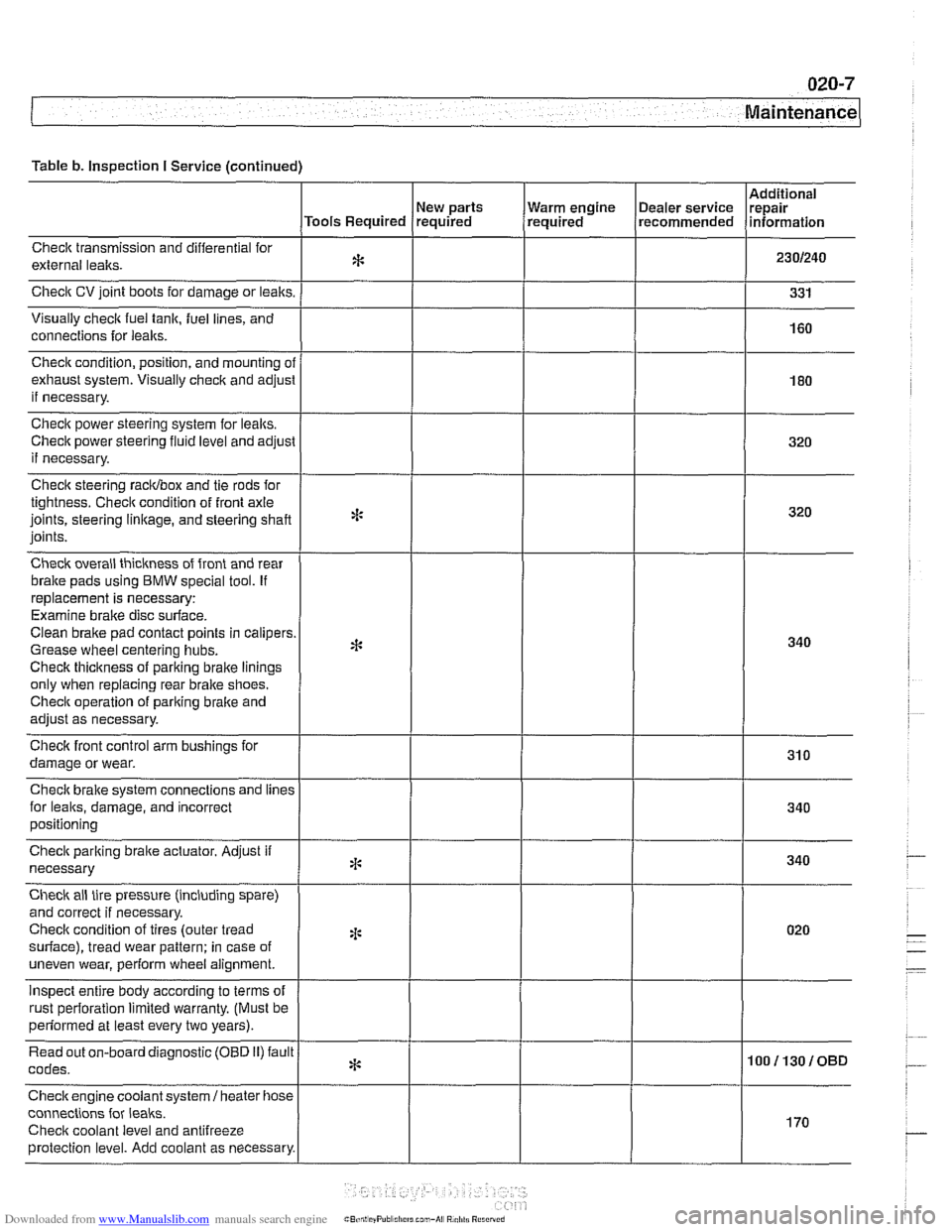
Table b. Inspection I Service (continued)
Checlt transmission and differential for
external lealts.
Check CV joint boots for damage or leaks.
Visually
check fuel tank, fuel lines, and
connections for
leaks.
New parts
Tools Required required
Check condition, position, and mounting
ol
exhaust system. Visually check and adjusl
if necessary.
Check power steering system for lealts.
Check power steering
fluid level and adjust
if necessary.
Check steering racidbox and tie rods for
tightness. Checit condition of front axle
joints, steering
linkage, and steering shaft
joints.
Check overall thickness of front and rear
bralte pads using
BMW special tool. If
replacement is necessary:
Examine brake disc surface.
Clean brake pad contact points in calipers
Grease wheel centering hubs.
Checlt thickness of parking brake linings
only when replacing rear brake shoes.
Checit operation of pariting brake and
adjust as necessary.
Checlt front control arm bushings for
damage or wear.
Check brake system connections and
lines
for leaks, damage, and incorrect
positioning Warm
engine
(~ealer service Irepair , required recommended lnformat~on
Check parking braite actuator. Adjust if
necessary
Check ail tire pressure (including spare)
and correct if necessary.
Checlt condition of tires (outer tread
surface), tread wear pattern: in case of
uneven wear, perform wheel alignment.
inspect entire body according to terms of
rust oerforation limited warrantv. (Must be
*:
4:
2 ~ perfdrmed at least every two years). I
Read out on-board diagnostic (OBD 11) fault
codes.
Checkengine coolant
system1 heater hose
connections for
leaks.
Checit coolant level and antifreeze
protection level. Add coolant as necessary.
* 100113010BD
I
170
Page 51 of 1002
Downloaded from www.Manualslib.com manuals search engine
Maintenance
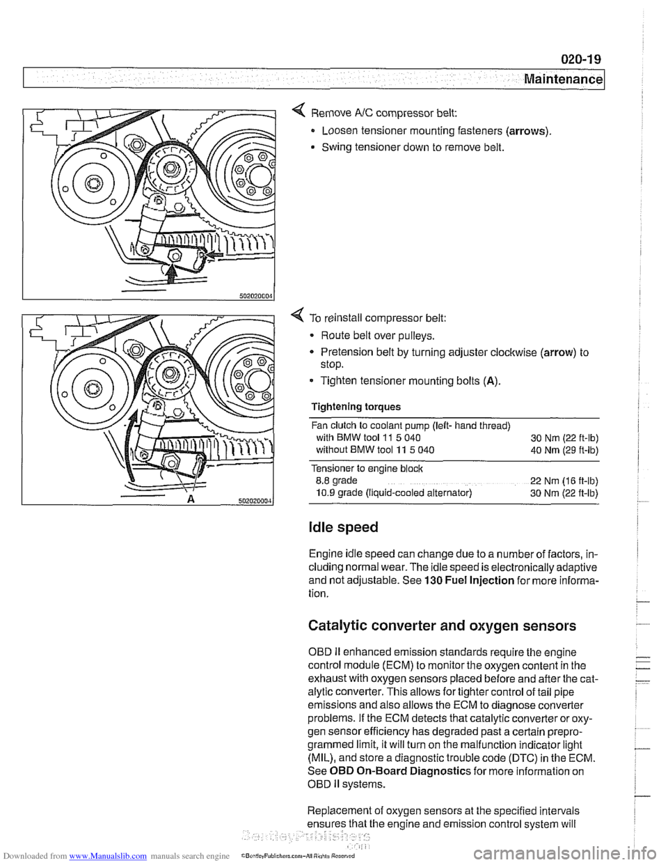
< Remove NC compressor belt:
Loosen tensioner mounting fasteners (arrows)
Swing tensioner down to remove belt.
4 To reinstall compressor belt:
Route belt over pulleys.
* Pretension belt by turning adjuster clockwise (arrow) to
stop.
- Tighten tensioner mounting bolts (A).
Tightening torques
Fan clutch to coolant pump (left- hand thread)
with BMW tool
11 5 040
30 Nm (22 ft-lb)
without BMW tool 11 5 040
40 Nm (29 ft-lb)
Tensioner to engine block
8.8 grade
22 Nm (16 ft-lb)
10.9 grade (Ilquid-cooled alternator) 30 Nm (22 ft-lb)
Idle speed
Engine idle speed can change due to a number of factors, in-
cluding normal wear. The idle speed is electronically adaptive
and not adjustable. See
130 Fuel Injection for more informa-
tion.
Catalytic converter and oxygen sensors
OBD II enhanced emission standards require the engine
control module (ECM) to monitor the oxygen content in the
exhaust with oxygen sensors placed before and after the cat-
alytic converter. This allows for tighter control of tail pipe
emissions and also allows the ECM to diagnose converter
problems. If the ECM detects that catalytic converter or oxy-
gen sensor efficiency has degraded past a certain
prepro-
grammed limit, it will turn on the malfunction indicator light
(MIL), and store a diagnostic trouble code (DTC) in the ECM.
See OBD On-Board Diagnostics for more information on
OBD
ll systems.
Replacement of oxygen sensors at the specified intervals
he engine and emission control system will
Page 60 of 1002
Downloaded from www.Manualslib.com manuals search engine
020-28
1 Maintenance
- When replacing fuel filter:
Use appropriate hose clamping device to clamp off filter
inlet and outlet hoses to lessen fuel spillage.
Loosen center clamping bracket and hose clamps on
either end of filter.
Note arrow or markings indicating direction of flow on
new filter.
Install new filter using new hose clamps
- Drain fuel filter from inlet side into a container and inspect
drained fuel.
Checlc for rust, moisture and contamination.
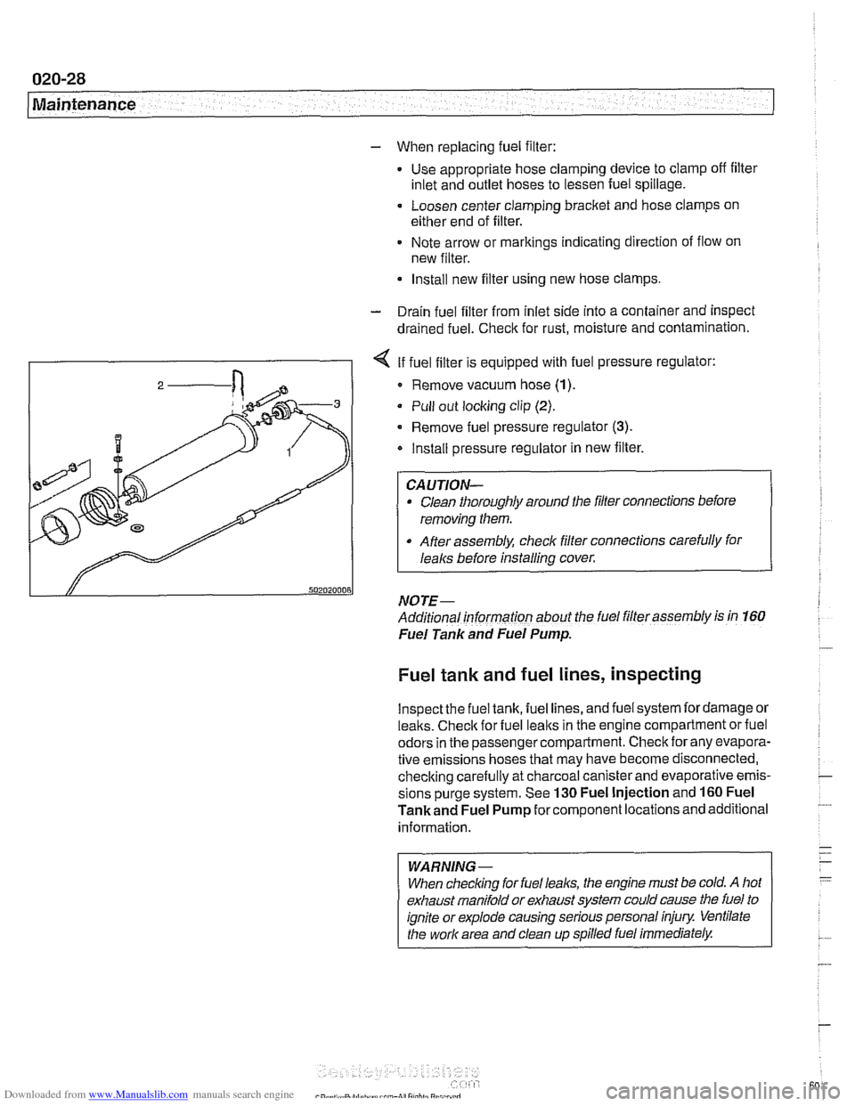
I - I < If fuel filter is equipped with fuel pressure regulator:
I 2 / Remove vacuum hose (1)
Pull out locking clip (2).
- Remove fuel pressure regulator (3).
Install pressure regulator in new filter.
Clean thoroughly around the filler connections before
removing them.
After assembly, check filter connections carefully for
I
I lealcs before installing cover.
NOTE- ~-
Additional informarion about the fuel filler assembly is in 160
Fuel Tank and Fuel Pump.
Fuel tank and fuel lines, inspecting
lnspectthe fuel tank, fuel lines, and fuel system fordamage or
lealts. Checlc for fuel lealts in the engine compartment or fuel
odors in the passenger compartment. Check for any evapora-
tive emissions hoses that may have become disconnected,
checking carefully at charcoal canister and evaporative emis-
sions purge system. See
130 Fuel Injection and 160 Fuel
Tankand Fuel Pump for component locations and additional
information.
WARNING-
When checlcing for fuel leal(s, the engine must be cold. A hot
exhaust manifold or exhaust system could cause the fuel to
ignite or explode causing serious personal injury Ventilate
the work area and clean up spilled fuel immediately.
Page 68 of 1002
Downloaded from www.Manualslib.com manuals search engine
Engine-General
This section covers system descriptions and general informa-
tion on engines and engine management systems. Also cov-
ered is basic engine troubleshooting.
For specific repair procedures, refer to the appropriate repair
group:
110 Engine Removal and Installation
0 113 Cylinder Head Removal and Installation
116 Cylinder Head and Valvetrain
0 117 Camshaft Timing Chain
119 Lubrication System
120 Ignition System
130 Fuel Injection
0 170 Radiator and Cooling System
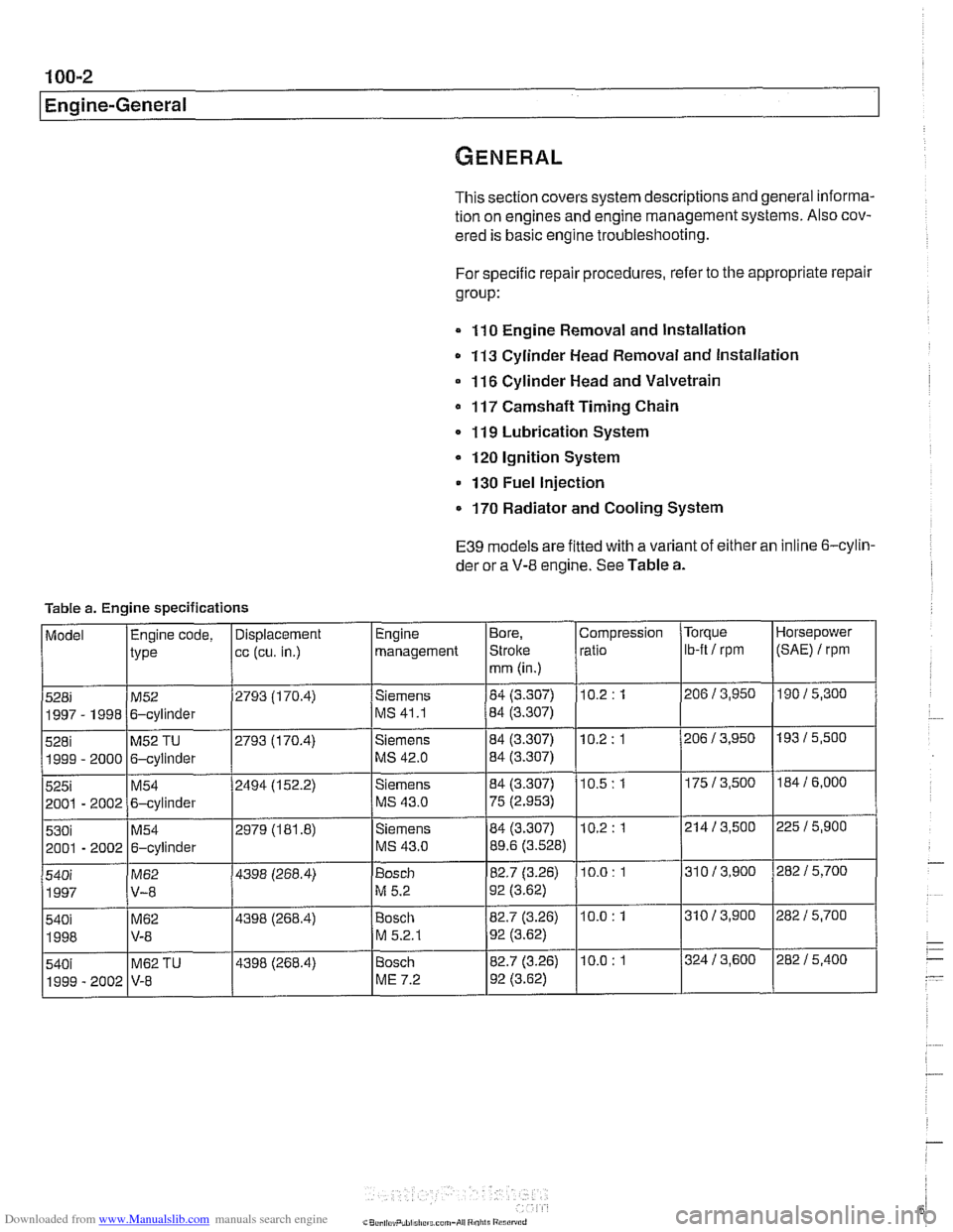
E39 models are fitted with a variant of either an inline 6-cylin-
der or a
V-8 engine. See Table a.
Table a. Engine specifications
Page 350 of 1002
Downloaded from www.Manualslib.com manuals search engine
Ignition System
This repair group covers component troubleshooting and re-
placement information for the ignition system.
When diagnosing engine management problems, including
on-board diagnostics (OBD
11) fault code analysis, also refer
to these repair groups:
* 130 Fuel Injection
* ELE Electrical Wiring Diagrams
OED On-Board Diagnostics
Special tools
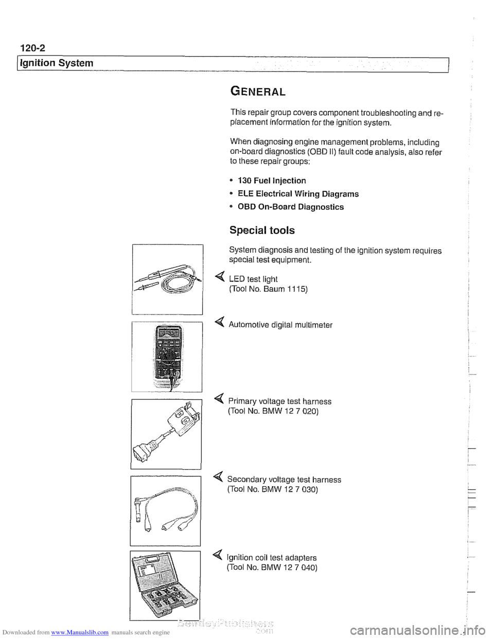
System diagnosis and testing of the ignition system requires
special test equipment.
4 LED test light
(Tool No. Baum
1 1 15)
4 Automotive digital multimeter
4 Primary voltage test harness
(Tool No. BMW 12
7 020)
-
4 Secondary voltage test harness
(Tool No. BMW 12
7 030)
Page 391 of 1002
Downloaded from www.Manualslib.com manuals search engine
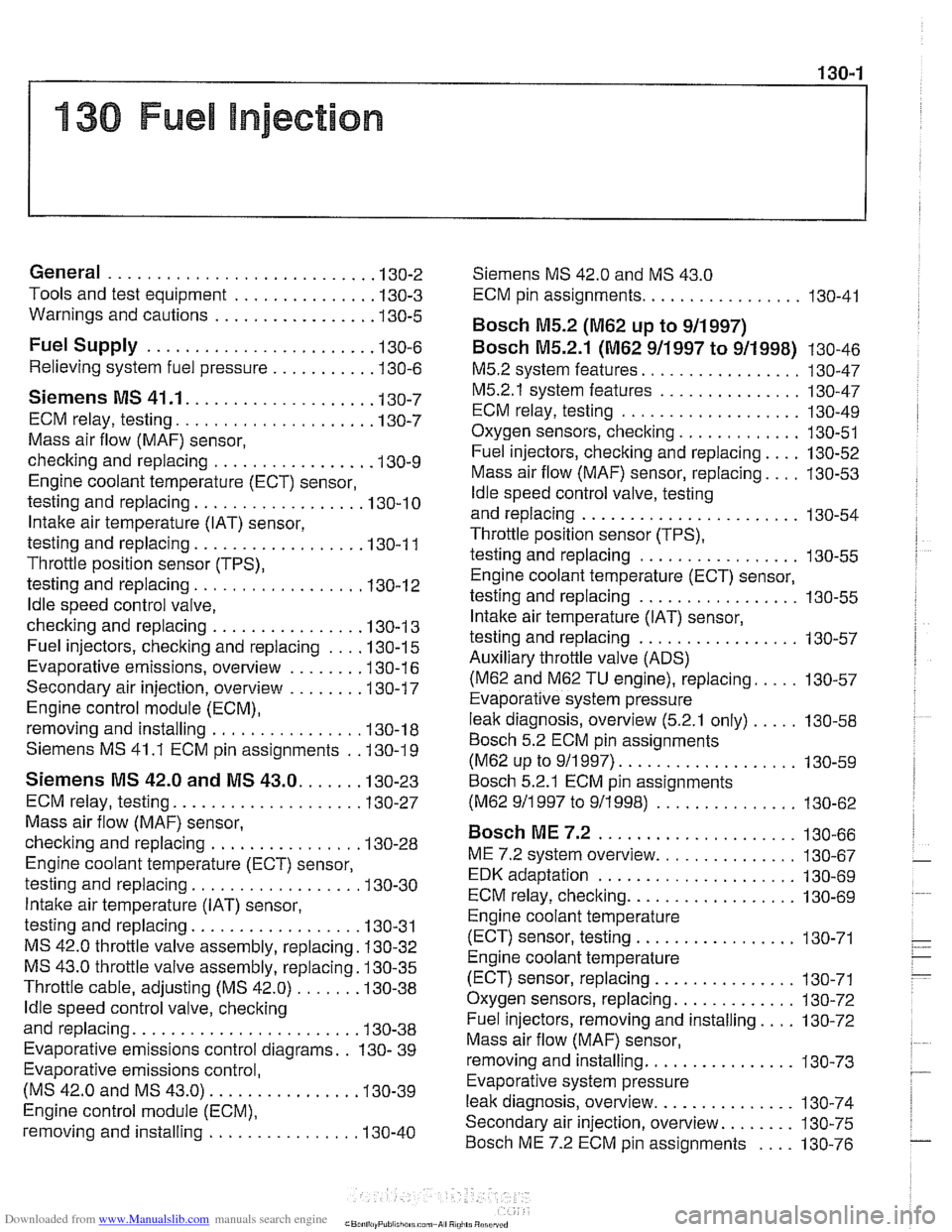
130-1
130 Fuel injection
General ........................... .I3 0.2
Tools and test equipment .............. .I3 0.3
Warnings and cautions ................ .I3 0.5
Fuel Supply ....................... .I3 0.6
Relieving system fuel pressure .......... .I3 0.6
Siemens MS 41 . 1. ................... 1 30-7
ECM relay. testing .................... .I3 0.7
Mass air flow (MAF) sensor.
checking and replacing
................ .I3 0.9
Engine coolant temperature (ECT) sensor.
testing and replacing
.................. 130-10
Intake air temperature (IAT) sensor.
testing and replacing
................. .I3 0.1 1
Throttle position sensor (TPS).
testing and replacing
.................. 130-1 2
ldle speed control valve.
checking and replacing
............... .I3 0.1 3
Fuel injectors. checking and replacing .... 130-15
Evaporative emissions. overview ....... .I3 0.1 6
Secondary air injection. overview ....... .I3 0-17
Engine control module (ECM).
removing and installing
................ 130-18
Siemens MS 41.1 ECM pin assignments . .I3 0.19
Siemens MS 42.0 and MS 43.0. ..... .I3 0.23
ECM relay. testing ................... .I3 0.27
Mass air flow (MAF) sensor.
checking and replacing
............... .I3 0.28
Engine coolant temperature (ECT) sensor.
testing and replacing
................. .I3 0.30
Intake air temperature (IAT) sensor.
testing and replacing
................. .I3 0.31
MS 42.0 throttle valve assembly. replacing . 130-32
MS 43.0 throttle valve assembly. replacing . 130-35
Throttle cable. adjusting (MS 42.0) ...... .I3 0.38
ldle speed control valve. checking
and replacing
....................... .I3 0.38
Evaporative emissions control diagrams . . 130- 39
Evaporative emissions control.
(MS
42.0 and MS 43.0). .............. .I3 0.39
Engine control module (ECM).
removing and installing
................ 130-40
Siemens MS 42.0 and MS 43.0
ECM pin assignments ................. 130-41
Bosch M5.2 (M62 up to 911997)
BOSC~ M5.2.1 (M62 911997 to 911998) 130-46
M5.2 system features ................. 130-47
M5.2.1 system features ............... 130-47
ECM relay. testing ................... 130-49
Oxygen sensors. checking ............. 130-51
Fuel injectors. checking and replacing .... 130-52
Mass air flow (MAF) sensor. replacing .... 130-53
ldle speed control valve. testing
and replacing
....................... 130-54
Throttle position sensor (TPS).
testing and replacing
................. 130-55
Engine coolant temperature (ECT) sensor.
testing and replacing
................. 130-55
Intake air temperature (IAT) sensor.
testing and replacing
................. 130-57
Auxiliary throttle valve (ADS) (M62 and
M62 TU engine). replacing ..... 130-57
Evaporative system pressure
leak diagnosis. overview
(5.2.1 only) ..... 130-58
Bosch 5.2 ECM pin assignments
(M62 UP to 911 997) ................... 130-59
~osch 5.2.1 ECM pin assignments
(M62 911 997 to 911 998) ............... 130-62
BOSC~ ME 7.2 ..................... 1 30-66
ME 7.2 system overview ............... 130-67
EDK adaptation ..................... 130-69
ECM relay. checking .................. 130-69
Engine coolant temperature
(ECT) sensor. testing
................. 130-71
Engine coolant temperature
(ECT) sensor. replacing
............... 130-71
Oxygen sensors. replacing ............. 130-72
Fuel injectors. removing and installing .... 130-72
Mass air flow (MAF) sensor.
removing and installing
................ 130-73
Evaporative system pressure
leak diagnosis. overview
............... 130-74
Secondary air injection. overview ........ 130-75
Bosch ME 7.2 ECM pin assignments .... 130-76
Page 392 of 1002
Downloaded from www.Manualslib.com manuals search engine
130-2
/Fuel Injection
This repair group covers service and repair of the Bosch and
Siemens engine management systems used on
1997
through 2002 E39 models. Additional engine management
service and repair information may also be found in the fol-
lowing repair groups:
0 020 Maintenance
120 Ignition System
160 Fuel Tank and Fuel Pump
610 Electrical Component Locations
OBD On Board Diagnostics
NOTE-
Camshaft position sensor, crankshaft speed sensor and
knoclc sensors are covered in 120 Ignition System.
Table a. Engine management system applications
- - ~ ~
1 ~odellmodel year / Engine IDME system I - I
5281, 1997-1 998 IM52. 2.8 liter ISiemens MS 41 .I I 1
528i. 1999ZO00 1~52 TU, 2.8 liter ]siemens MS 42.0 I I
5251, 2001-2002 1~54, 2.5 liter 1 Siemens MS 43.0 I I
530i, 2001-2002 1~54, 3.0 liter ISiemens MS 43.0
5401 1999-2001 1~62 TU, 4.4 liter l~osch ME 7.2
I
OBI) II software and hardware is incorporated in the engine
management control systems. The
OED II system monitors
components that influence exhaust and evaporative emis-
sions. If a problem is detected, the
OED I1 system stores the
associated fault code and condition.
540i. 1997
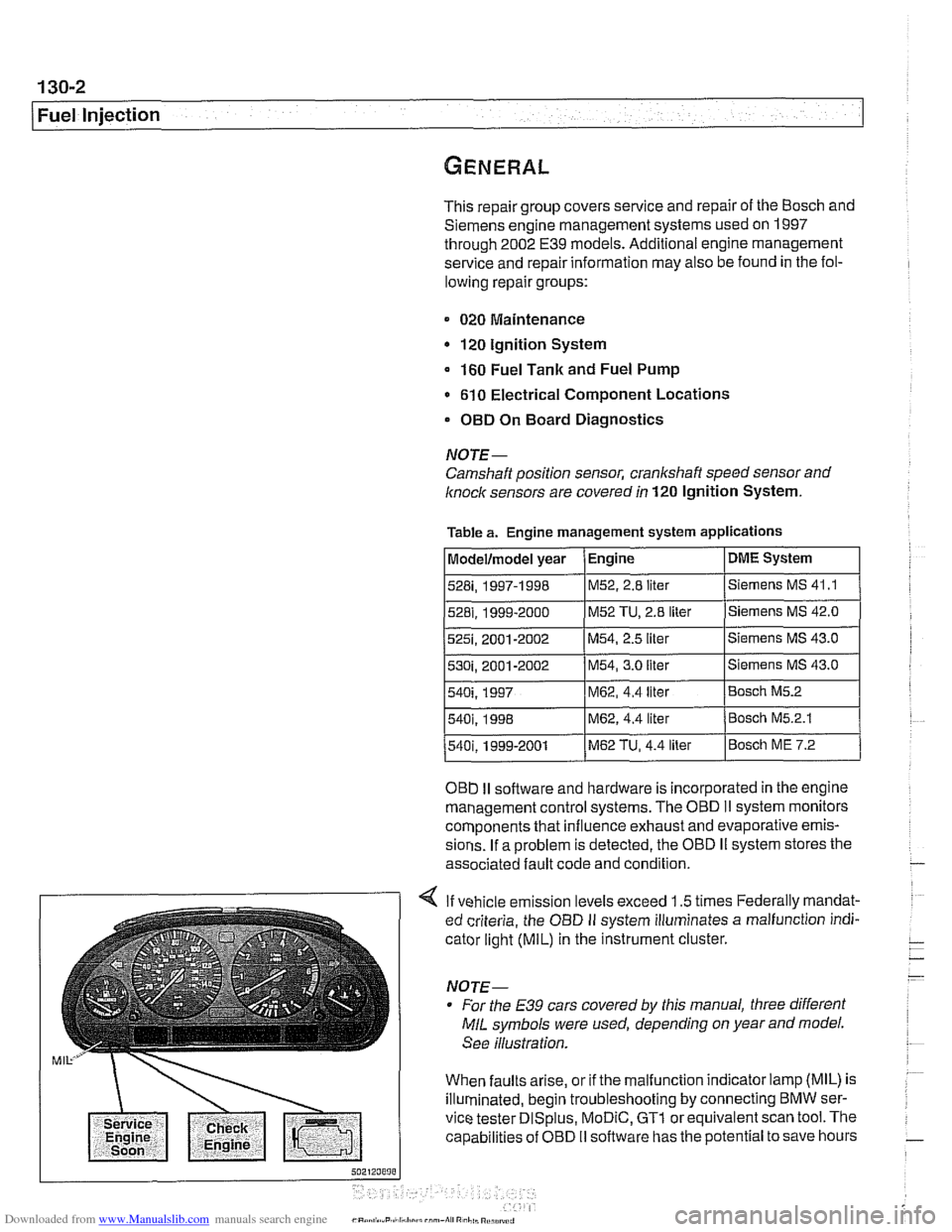
4 If vehicle emission levels exceed 1.5 times Federally mandat-
ed criteria, the
OED II system illuminates a malfunction indi-
cator light
(MIL) in the instrument cluster.
For the
E39 cars covered by this manual, three different
MIL symbols were used, depending on year and model.
See illustration.
When faults arise, or if the malfunction indicator lamp (MIL) is
illuminated, begin troubleshooting by connecting BMW ser-
vice tester
DISplus, MoDiC, GTl or equivalent scan tool. The
capabilities of OBD
II software has the potential to save hours
540i. 1998 IM62, 4.4 liter /Bosch M5.2.1
M62, 4.4 liter Bosch M5.2
Page 396 of 1002
Downloaded from www.Manualslib.com manuals search engine
130-6
Fuel Injection
Fuel supply to the injection system is provided by a high pres-
sure electric pump mounted inside the fuel tank. The pump is
powered via the fuel pump relay. If the relay is faulty, the fuel
pump will not run and the engine will not start.
NOTE-
* Fuel delivery volume and fuel pressure are critical to prop-
er operation. Fuel pressure direcfly influences fuel deliv-
ery
Fuel pump relay, fuel pressure and fuel volume tests are
given in 160 Fuel Tank and Fuel Pump.
Relieving system fuel pressure
The fuel system retains fuel pressure in the system when the
engine is off. To prevent fuel from spraying on a hot engine,
system fuel pressure should be relieved beforedisconnecting
fuel lines. One method is to tightly wrap
ashop towel around a
fuel line fitting and loosen or disconnect the fitting. Cleanli-
ness is essential when working with fuel components. Thor-
oughly clean the unions before disconnecting fuel lines.
When system faults are detected, a diagnostic trouble code
(DTC) is stored in the engine control module (ECM). The MIL
also iiluminates if an emissions-related fault is detected
When faults arise, or if the malfunction indicator lamp (MIL) is
illuminated, begin troubleshooting by connecting BMW ser-
vice tester
DISplus. MoDiC, GTI or equivalent scan tool. The
capabilities of OBD
II software has the potential to save hours
of diagnostic time and to help avoid incorrect component re-
placement and possible damage to system components.
CAUTION-
- The tests in this section may set fault codes (DTCs) in the
ECM and illuminate the
MIL. Affer all testing is completed,
access and clear DJC fault memory using an
OED I1 or
BMW compatible scan tool. See OBD On-Board Diag-
nostics.
0 Only use a digital multimeter for electrical tests.
. Relay positions can vary Be sure to confirm relay posi-
tion by identifying the wiring in the socket using the wir-
ing diagrams found in ELE Electrical Wiring
Diagrams.
Page 397 of 1002
Downloaded from www.Manualslib.com manuals search engine
Fuel Injection 1
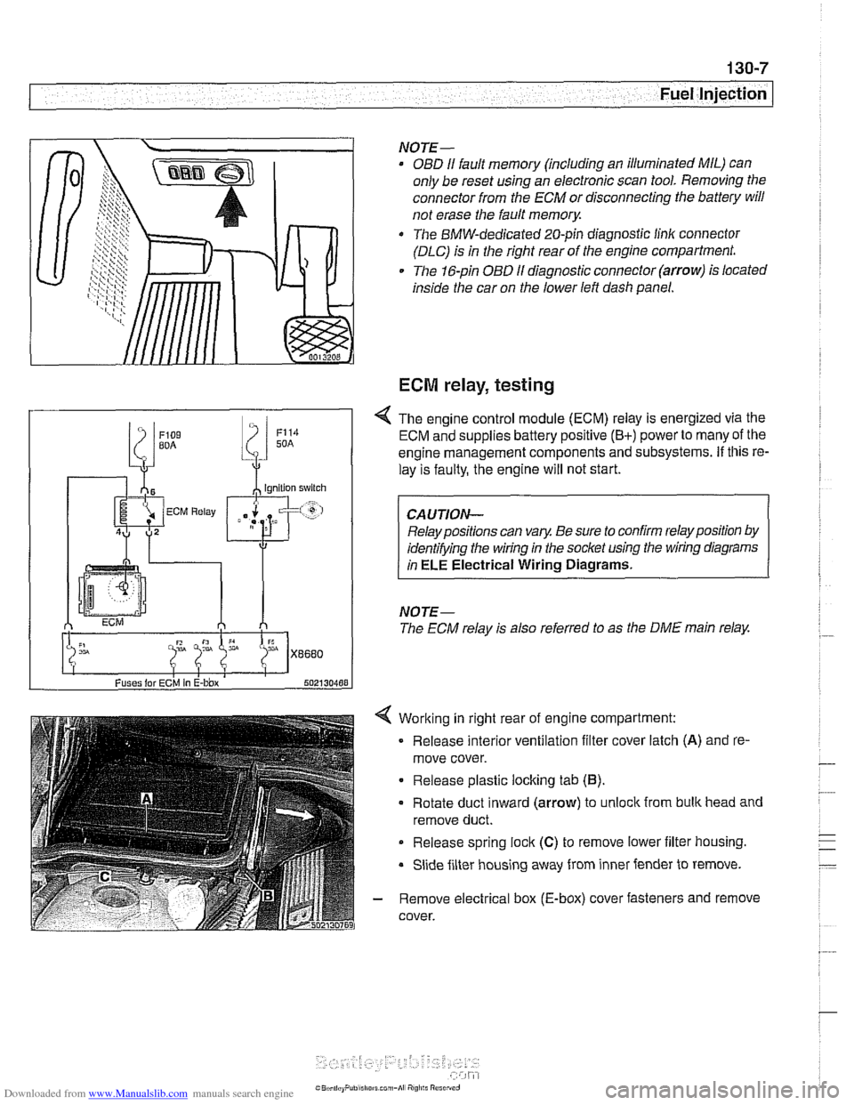
Working in right rear of engine compartment:
Release interior ventilation filter cover latch
(A) and re-
move cover.
Release plastic locking tab
(6).
Rotate duct inward (arrow) to unlock from bulk head and
remove duct.
Release spring
lock (C) to remove lower iilter housing.
Slide filter housing away from inner fender to remove.
- Remove electrical box (E-box) cover fasteners and remove
cover.
NOTE-
OBD I1 fault memory (including an illuminated MIL) can
only be reset using an electronic scan tool. Removing the
connector from the ECM or disconnecting the battery will
not erase the fault
memory.
The BMW-dedicated 20-pin diagnostic linlc connector
(DLC) is in the right rear of the engine compartment.
The 16-pin OBD
I1 diagnostic connector (arrow) is located
inside the car on the lower left dash panel.
ECM relay, testing
Fuses lor ECM In E-bbx 502130488
4 The engine control module (ECM) relay is energized via the
ECM and supplies battery positive
(B+) power to many of the
engine management components and subsystems.
If this re-
lay is faulty, the engine will not start.
Relay positions can vary. Be sure to confirm relay position by
identifying the wiring in the socket using the wiring diagrams
in
ELE Electrical Wiring Diagrams.
NOTE-
The ECM relay is also referred to as the DME main relay.