Vol 2 BMW 528i 2000 E39 Owners Manual
[x] Cancel search | Manufacturer: BMW, Model Year: 2000, Model line: 528i, Model: BMW 528i 2000 E39Pages: 1002
Page 896 of 1002
Downloaded from www.Manualslib.com manuals search engine
51 5-2
/Central Locking and Anti-Theft
This section covers repair information for door, trunk and car-
go compartment locks, central locking, electronic
immob~liza-
tion (EWS) and anti-theft alarm (DWA).
€39 cars are equipped with sophisticated self-diagnostic elec-
trical systems. When experiencing malfunctions relating to
central locking. EWS or anti-theft systems, start the diagnosis
process using the
BMW service tester DIS, GT 1, MoDiC or
equivalent scan tool. An advanced diagnostic scan tool can
usually pinpoint electrical faults quickly and safely.
Additional electrical information can be found in:
610 Electrical Component Locations
ELE Electrical Wiring Diagrams
Central locking in E39 vehicles controls the door
locks, trunk
or tailgate lock and fuel filler flap lock. The control module for
the Central Body Electronics system (ZKE
Ill), lknown as the
General Module (GM
Ill), controls central locking.
ZKE
Ill manages the following central locking related func-
tions:
Central locking
* Keyless entry
Key memory
Power trunk release
Electric opening of tailgate
DWA alarm system
Diagnosis
General Module
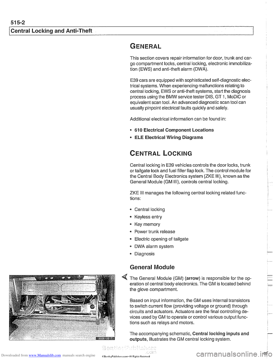
4 The General Module (GM) (arrow) is responsible for the op-
eration of central body electronics. The GM is located behind
the glove compartment.
Based on input information, the GM uses internal transistors
to switch current flow (providing voltage or ground) through
circuits and actuators. Actuators are the final controlling de-
vices used by GM to operate or control various output func-
tions such as relays and motors.
The accompanying schematic, Central locking inputs and
outputs, illustrates the GM central locking system.
Page 904 of 1002
Downloaded from www.Manualslib.com manuals search engine
1 Central Locking and Anti-Theft
NOJE-
A single unlock request from the driver's door with the FZV
key unlocks the driver's door only.
A second unlock request
unlocls the remaining doors and trunk. This feature can be
modified for individual users with the Key Memory capabil-
ities to activate all lock actuators simultaneously See Car
Memory
/ Key Memory later in this section.
Starting with 2000 models, the battery in the FZV ignition
Icey is recharged by the ignition switch ring antenna while
the ley is in the ignition switch.
Transmitter self-test (models to
1999)
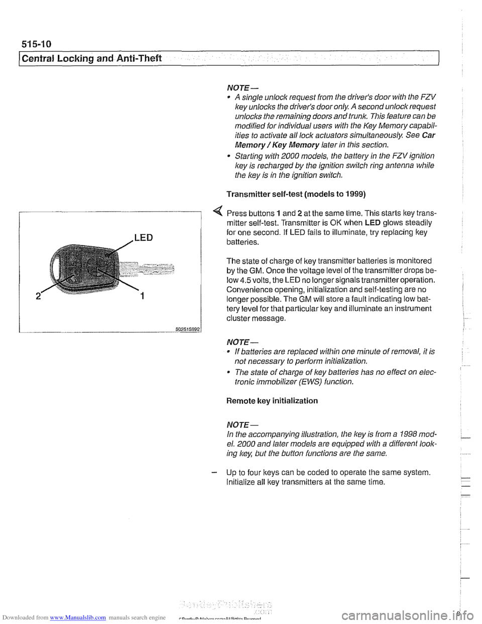
Press buttons 1 and 2 at the same time. This starts ltey trans-
/ mitter self-test. Transmitter is OK when LED glows steadily
te{le"el for that particular key and illuminate an instrument
cluster message.
-- 502515092 J
NO JE-
If batteries are replaced within one minute of removal, it is
not necessary to
periorm initialization.
Tlie state of charge of key batteries has no effect on elec-
tronic immobilizer (EWS) function.
2
Remote key initialization
for one second. If LED fails to illuminate, try replacing ltey~
batteries.
The state of charge of key transmitter batteries is monitored
by the
GM. Once the voltage level of the transmitter drops be-
low
4.5volts, the LED no longersignals transmitteroperation.
Convenience opening, initialization and self-testing are no
lonaer ~ossible. The GM will store a fault indicatina low bat-
NOJE-
In the accompanying illustration, the key is from a 1998 mod-
el. 2000 and later models are equipped with a different look-
ing
/
Initialize all key transmitters at the same time.
Page 936 of 1002
Downloaded from www.Manualslib.com manuals search engine
1 Sunroof
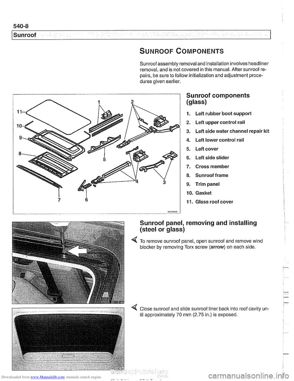
Sunroof assembly removal and installation involves headliner
removal, and is not covered in this manual. After sunroof re-
pairs, be sure to follow initialization and adjustment proce-
dures given earlier.
I Sunroof comDonents
1. Left rubber boot suppori
2. Left upper control rail
3. Left side water channel repair ltit
4. Left lower control rail
5. Left cover
6. Left side slider
7. Cross member
8. Sunroof frame
9. Trim panel
10. Gasket
11. Glass roof cover
m5sm.7 - -.
Sunroof panel, removing and installing
(steel or glass)
4 To remove sunroof panel, open sunroof and remove wind
blocker
by removing Tom screw (arrow) on each side.
Page 969 of 1002
Downloaded from www.Manualslib.com manuals search engine
On-Board Diagnostics
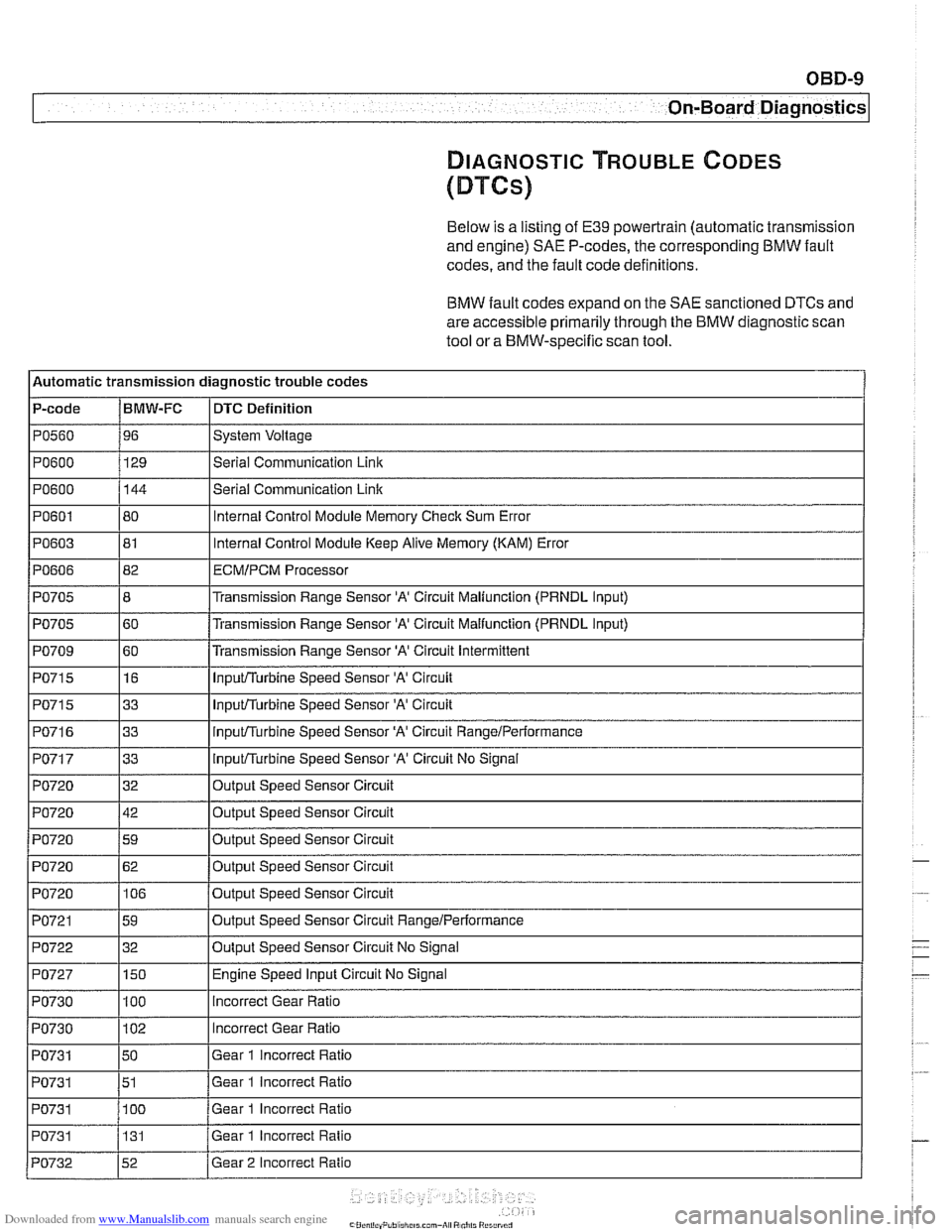
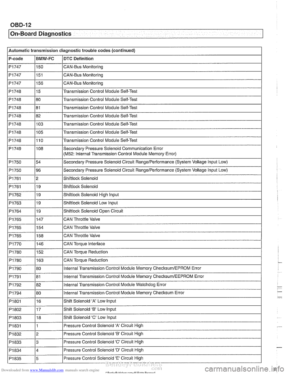
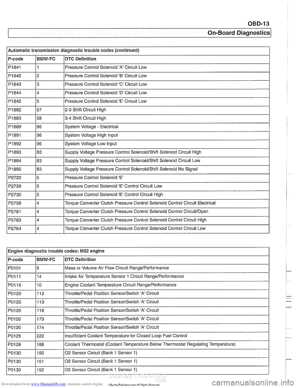
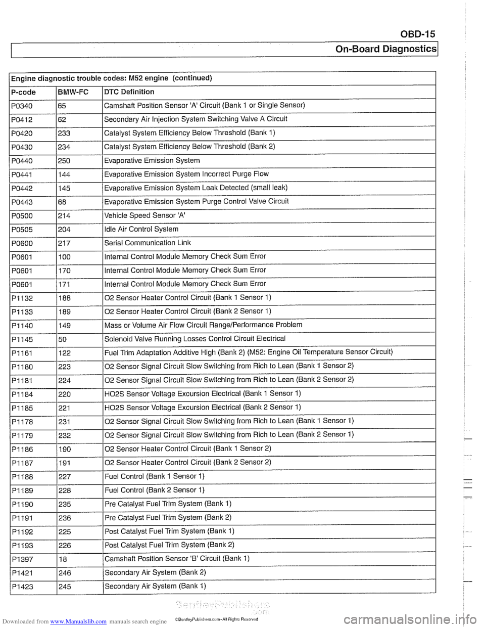
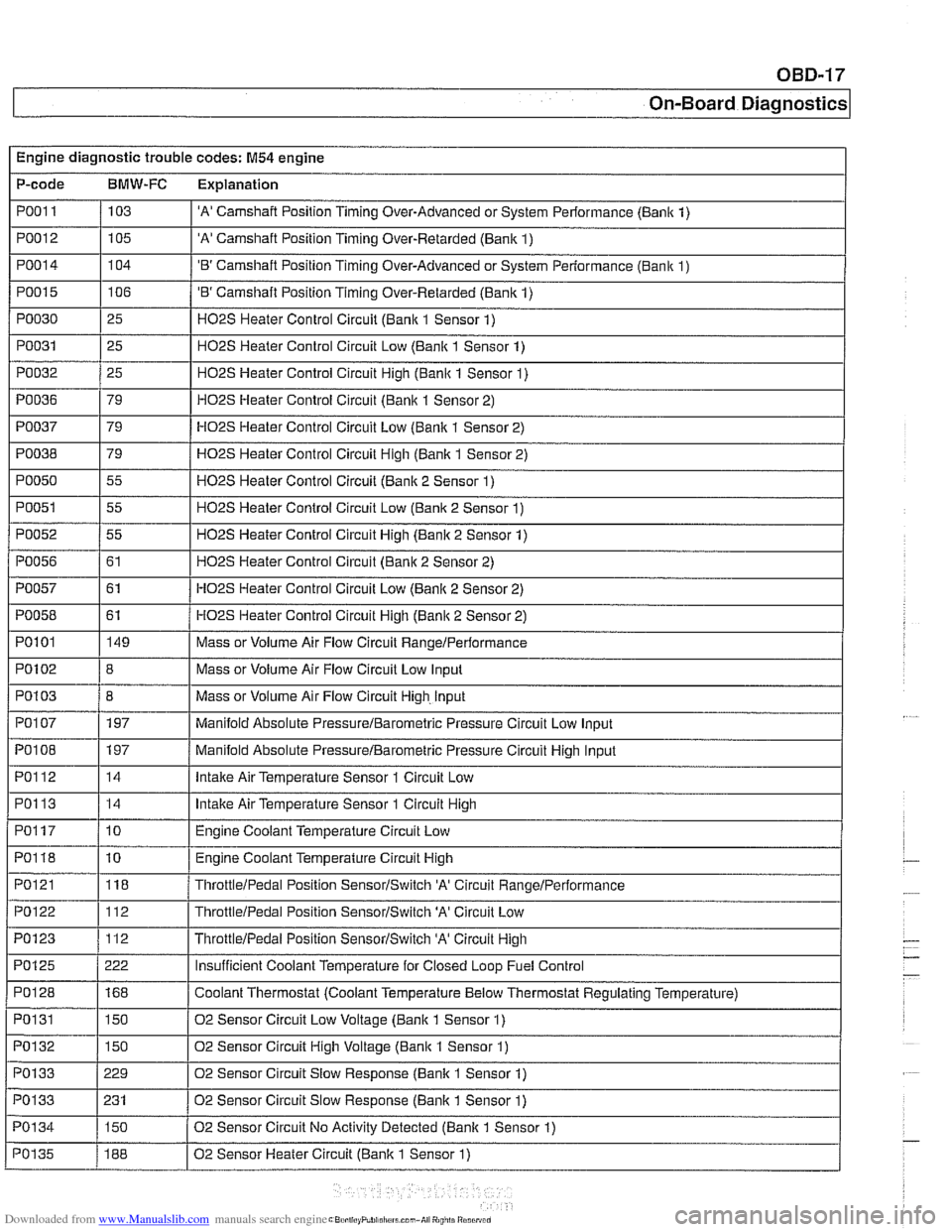
DIAGNOSTIC TROUBLE CODES
(DTCs)
Below is a listing of E39 powertrain (automatic transmission
and engine)
SAE P-codes, the corresponding BMW fault
codes, and the fault code definitions.
BMW fault codes expand on the SAE sanctioned DTCs and
are accessible primarily through the BMW diagnostic scan
tool or a BMW-specific scan tool.
l~utomatic transmission diagnostic trouble codes
P-code
IBMW-FC I DTC Definition
Ip0560 196 ISystem Voltage I
IPO~OO I129 l~eriai Communication Link I
1~0715 116 I InpuVTurbine Speed Sensor 'A' Circuit I
PO600
PO601
PO603
PO606
PO705
PO705
PO709
144
80
81
82
8
60
60
PO71 5
PO71 6
PO717
PO720
PO720
PO720
I I
PO721 159 loutput Speed Sensor Circuit RangeIPerformance I
Serial Communication Link
Internal Control Module Memory Check Sum Error
Internal Control Module Keep Alive Memory (KAM) Error
ECMIPCM Processor
Transmission Range Sensor 'A' Circuit Maliunction (PRNDL Input)
Transmission Range Sensor
'A' Circuit Malfunction (PRNDL input)
Transmission Range Sensor
'A' Circuit Intermittent
I I'
1~0722 132 IOutput Speed Sensor Circuit No Signal I
33
33
33
32
42
59
PO720
I I
PO727 1150 I Engine Speed Input Circuit No Signal
InpuVTurbine Speed Sensor 'A' Circuit
inpuVTurbine Speed Sensor 'A' Circuit RangeiPerformance
InpuVTurbine Speed Sensor 'A' Circuit No Signal
Output Speed Sensor Circuit
Output Speed Sensor Circuit
Out~ut Speed Sensor Circuit
PO720 1106 /output Speed Sensor Circuit
62
Output Speed Sensor Circuit
PO730
PO730
PO731
PO731
PO731 I I
100
102
50
51
100
PO731
incorrect Gear Ratio
Incorrect Gear Ratio
Gear 1 incorrect Ratio
Gear 1 incorrect Ratio
Gear 1 Incorrect Ratio
PO732 152 /Gear 2 Incorrect Ratio
131
Gear
1 Incorrect Ratio
Page 972 of 1002
Downloaded from www.Manualslib.com manuals search engine
OBD-12
On-Board Diagnostics
Automatic transmission diagnostic trouble codes (continued)
P-code
PI747
PI747
PI 747
PI748
PI748 I I
PI748
PI748
PI748
PI 748
PI 749
PI 750
P1750
PI761
PI761
BMW-FC
150
151
156
15
80
-- PI762
PI763
PI764
PI765
PI765
PI765
P1770
DTC Definition
CAN-BUS Monitoring
CAN-Bus Monitoring
CAN-Bus Monitoring
Transmission Control Module Self-Test
Transmission
Control Module Self-Test
PI748 182 l~ransmission Control Module Self-Test
81
103
105
110
I I
Transmission Control Module Self-Test
Transmission Control Module Self-Test
Transmission Control Module Self-Test
Transmission Control Module Self-Test
19
19
19
147
154
158
146
PI 790
PI791
P1792
PI 794
PI 801
P1802
PI 803
PI 831 Shiftiock Solenoid High input
Shiftlock Solenoid
Low Input
Shiftlock Solenoid Open Circuit
CAN Throttle Valve
CAN Throttle Valve
CAN Throttle Valve
CAN
Torpue Interlace
CAN Torque Reduction
PI 780
I I -
108
54
96
2 19
PI 780 1163 ICAN Torque Reduction
152
80
81
82
80
16
17 18
1 Secondary Pressure Solenoid Communication Error
(M52: Internal
Transmission Control Module Memory Error)
Secondary Pressure Solenoid Circuit
Rangelperformance (System Voltage Input Low)
Secondary Pressure Solenoid Circuit
RangeIPerformance (System Voltage Input Low)
Shiftioclc Solenoid
Shiftiocic Solenoid
internal Transmission Control Module Memory ChecksumlEPROM Error
internal Transmission Control Module Memory
ChecksumIEEPROM Error
internal Transmission Control Module Watchdog Error
internal Transmission Control Module Memory Checksum Error
Shift Solenoid
'A' Low Input
Shift Solenoid
'8' Low Input
Shift Solenoid
'C' Low input
Pressure Control Solenoid
'A' Circuit High
Pressure Control Solenoid 'B' Circuit High
PI832
PI833 13 IPressure Control Solenoid 'C' Circuit High
2
Page 973 of 1002
Downloaded from www.Manualslib.com manuals search engine
On-Board Diagnostics
l~utomatic transmission diagnostic trouble codes (continued)
P-code
1 Pi844
I I
14 /Pressure Control Solenoid 'D' Circuit Low
I I PI841 11 /Pressure Control Solenoid 'A' Circuit Low
BMW-FC
Pi842
I
P2722 15 I Pressure Control Solenoid 'E' I
DTC
Definition
Pi 845
Pi 882
Pi 883
PI 889
PI891
PI 892
PI 893
Pi 843 3 8
2 Pressure Control Solenoid '0' Circuit Low
5
57
58
96
96
96
83
P2729
P2730
P2759
P2761
P2763
P2764
Pressure Control Solenoid 'E' Circuit Low
2-3 Shift Circuit High
3-4 Shift Circuit High
System Voltage
- Electrical
System Voltage High Input
System Voltage Low Input
SUDP~V Voltaqe Pressure Control SoienoidIShift Solenoid Circuit High
~~ ~~ ~ Engine diagnostic trouble codes: M52 engine
5
5
4
4
4
4
I I
Pressure Control Solenoid 'E' Control Circuit Low
Pressure Control Solenoid
'E' Control Circuit High
Torque Converter Clutch Pressure Control
Solenoid Control Circuit Electrical
Torque Converter Clutch Pressure Control Solenoid Control
Circuitlopen
Torque Converter Clutch Pressure Control Solenoid Control Circuit High
Torque Converter Clutch Pressure Control Solenoid Control Circuit Low
DTC Definition
Mass or Volume Air
Flow Circuit RangeIPerformance
lntalte Air Temperature Sensor 1 Circuit Rangelperformance
Engine Coolant Temperature Circuit RangeIPerformance
ThrottieIPedai Position SensorISwitch 'A' Circuit
ThrottleIPedai Position SensorISwitch 'A' Circuit
P-code
PO1
01
PO1 11
PO116
PO120
PO120
PO1 20 BMW-FC
8 14
10
112
113
POI 20 1173 /~hrottie/~edal Position SensorISwitch 'A' Circuit
118
ThrottieIPedai Position SensorISwitch 'A' Circuit
Page 975 of 1002
Downloaded from www.Manualslib.com manuals search engine
OBD-15
On-Board ~iagnosticsl
Engine diagnostic trouble codes: M52 engine (continued)
P-code
PO340
PO412
PO420
PO430
PO440
PO441
PO442
PO443
PO500
PO505
PO600
PO601
PO601
I PO601
~1132
~1133
BMW-FC
65
62
233
234
250 144
-
145
68
214
i I
DTC Definition
Camshalt Position Sensor 'A' Circuit (Bank 1 or Single Sensor)
Secondary Air Injection System Switching Valve A Circuit
Catalyst System Efficiency Below Threshold
(Bank 1)
Catalyst System Efficiency Below Threshold (Bank 2)
Evaporative Emission System
Eva~orative Emission Svstem Incorrect Purge Flow .
Evaporative Emission System Leak Detected (small leak)
Evaporative Emission System Purge Control Valve Circuit
Vehicle Speed Sensor 'A'
204
21 7
100
170
171
188
189
PI161
PI180
PI181
PI184
PI185
PI178
02 Sensor Heater Control Circuit (Bank 2 Sensor 2) I
idle Air Control System
Serial Communication
Link
Internal Control Module Memory Check Sum Error
Internal Control Module Memory
Check Sum Error
Internal Control Module Memory
Check Sum Error
02 Sensor Heater Control Circuit (Bank 1 Sensor
1)
02 Sensor Heater Control Circuit (Bank 2 Sensor 1)
Mass or Volume Air Flow Circuit RangeIPerlormance Problem PI140
I
I I
P1188 1227 I Fuel Control (Bank 1 Sensor 1)
PI145 150 /Solenoid Valve Running Losses Control Circuit Electrical
149
122
223
224
220 221
231
I I
P1189 1228 I Fuel Control (Banlc 2 Sensor 1)
Fuel Trim Adaptation Additive High (Bank 2) (M52: Engine Oil Temperature Sensor Circuit)
02 Sensor Signal Circuit Slow Switching from Rich to Lean
(Bank 1 Sensor 2)
02 Sensor Signal Circuit Slow Switching from Rich to Lean
(Bank 2 Sensor 2)
H02S Sensor Voltage Excursion Electrical (Banlc 1 Sensor 1)
HO2S Sensor Voltage Excursion Electrical (Banlc 2 Sensor 1)
02 Sensor Sianai Circuit Slow Switchina from Rich to Lean (Bank 1 Sensor 1)
02 Sensor Signal Circuit Slow Switching from Rich to Lean (Bank 2 Sensor 1) PI179
I I
PI190 1235 I Pre Catalyst Fuel Trim System (Banlc 1)
PI186 1190 102 Sensor Heater Control Circuit (Banlc 1 Sensor 2)
232
I I
PI191 1236 I Pre
Catalyst Fuel Trim System (Banlc 2)
PI192
. . -- - i Pi193 1226 I Post Catalvst Fuel Trim Svstem (Bank 2)
225
PI397
I I
Post Catalyst Fuel Trim System (Bank 1)
PI421 1246 /Secondarv Air System (Bank 2)
18
Secondary Air System (Bank
1) PI423
Camshaft Position Sensor '0' Circuit (Bank 1)
I 245
Page 977 of 1002
Downloaded from www.Manualslib.com manuals search engine
On-Board ~iaanosticsl
Engine diagnostic trouble codes: M54 engine
P-code
BMW-FC Explanation
PO01 I / 103 I 'A' Camshaft Position Timing Over-Advanced or System Performance (Banlc 1) I I
PO012 1105 I 'A' Camshaft Position Timing Over-Retarded (Bank 1) I I
PO01 4 1104 I 'B' Camshaft Position Timing Over-Advanced or System Performance (Bank 1)
PO01 5
PO030
PO031
PO032
I 1
PO038 179 / HO2S Heater Control Circuit High (Bank 1 Sensor 2)
I I -.
I I
PO050 1 55 I H02S Heater Control Circuit (Bank 2 Sensor 1)
106
25
25
25
PO036
I I
PO051 1 55 I H02S Heater Control Circuit Low (Bank 2 Sensor 1)
'B' Camshaft Position Timing Over-Retarded (Bank 1)
H02S Heater Control Circuit (Bank 1 Sensor 1)
H02S Heater Control Circuit Low (Bank 1 Sensor 1)
H02S Heater Control Circuit Hiqh (Bank 1 Sensor 1)
PO037 1 79 I HO2S Heater Control Circuit Low (Bank 1 Sensor 2)
79
HOPS Heater
Control Circuit (Banlc 1 Sensor 2)
PO052
PO056
PO057
PO058
I I
PO1 03 / 8 I Mass or Volume Air Flow Circuit High. Input
I I -.
I I
PO1 07 1 197 I Manifold Absolute PressureIBarometric Pressure Circuit Low Input
55
61
61
61
PO101
I I
POI08 1197 / Manifold Absolute PressureIBarometric Pressure Circuit High Input
H02S Heater Control Circuit High (Bank 2 Sensor 1)
H02S Heater Control Circuit (Bank 2 Sensor 2)
HO2S Heater Control Circuit Low (Bank 2 Sensor 2)
HO2S Heater Control Circuit Hiqh (Banlc 2 Sensor 2)
PO102 18 I Mass or Volume Air Flow Circuit Low Input
149
I I -
PO122 112 ThrottleIPedai Position SensorISwitch 'A' Circuit Low
PO123 1112 I ThrottleIPedal Position SensorISwitch 'A' Circuit High
Mass
or Volume Air Flow Circuit
RangeIPerformance
PO112
PO113
PO1 17
PO118
PO121
14
14
10
10
118
PO128
PO1 31
PO132
PO133
PO133
PO1 34 Intake
Air Temperature Sensor 1 Circuit Low
Intake Air Temperature Sensor 1 Circuit High
Engine Coolant Temperature Circuit Low
Engine Coolant Temperature Circuit High
ThrottleIPedal Position SensorISwitch 'A' Circuit RanqeIPerformance
I I
168
150
150
229
231
150
PO135
Coolant Thermostat (Coolant Temperature Below Thermostat Regulating Temperature)
02 Sensor Circuit Low Voltage (Bank 1 Sensor 1)
02 Sensor Circuit High Voltage (Bank 1 Sensor 1)
02 Sensor Circuit Slow Response (Bank
1 Sensor 1)
02 Sensor Circuit Slow Response
(Banlc 1 Sensor 1)
02 Sensor Circuit No Activitv Detected
(Banlc 1 Sensor 1)
188 02 Sensor Heater Circuit (Bank 1 Sensor 1)
Page 980 of 1002
Downloaded from www.Manualslib.com manuals search engine
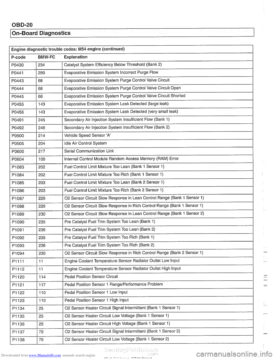
I On-Board Diagnostics
Engine diagnostic trouble codes: M54 engine (continued)
P-code
BMW-FC Explanation
Catalyst System Efficiency Below Threshold (Bank 2)
PO430
PO443
PO444
PO445
PO455
PO456
PO491
PO492
PO500
PO441 1250 / Evaporative Emission System Incorrect Purge Flow
234
I I
68
68
68 143
143
245
246
214
PO604
PI083
PI084
PI085
PI086
Evaporative Emission System Purge Control Valve Circuit
Evaporative Emission System Purge Control Valve Circuit Open
Evaporative Emission System Purge Control Valve Circuit Shorted
Evaporative Emission System Leak Detected (large leak)
Evaporative Emission System Leak Detected (very
small leak)
Secondary Air injection System Insufficient Flow (Bani( 1)
Secondary Air Injection System insufficient Flow
(Banic 2)
Vehicle Speed Sensor
'A'
Idle Air Control System PO505
.
PI 087
PI 088
PI089
PI090
PO600 / 217 I Serial Communication Link
204
100
202
202
203
203
PI091
PI092
PI093
PI094
Pllll
PI112
PI120
Internal Control Module Random Access Memory (RAM) Error
Fuel Control Limit Mixture Too Lean (Bank 1 Sensor
1)
Fuel Control Limit Mixture Too Rich (Bank 1 Sensor 1)
Fuel Control Limit Mixture Too Lean (Bank 2 Sensor 1)
Fuel Control Limit Mixture Too Rich (Banic 2 Sensor 1) ~ ~
229
229
230 235
PI121
PI122
PI123
02 Sensor Circuit Slow Response in Lean Control Range (Bank 1 Sensor 1)
02 Sensor Circuit Slow Response in Rich Control Range (Bank 1 Sensor
1)
02 Sensor Circuit Slow Response in Lean Control Range (Banlc 1 Sensor 2)
Pre Catalyst Fuel Trim System Too Lean
(Bank 1)
236
235
236
230
11
11
114
PI134
PI135
PI136
PI137
PI138
Pre Catalyst Fuel Trim System Too Lean (Banic 2)
Pre Catalyst Fuel Trim System Too Rich
(Bank 1)
Pre Catalyst Fuel Trim System Too Rich (Bank 2)
02 Sensor Circuit Slow Response in Rich Control Range (Banic 2 Sensor 1)
Engine Coolant Temperature Sensor Radiator Outlet Low Input
Engine Coolant Temperature Sensor Radiator Outlet High Input
Pedal Position Sensor Circuit
117
110
110
25
25
25
79
79 Pedal Position Sensor 1
RangeIPerformance Problem
Pedal Position Sensor 1 Low Input
Pedal Position Sensor 1 High Input
02 Sensor Heater Circuit Signal Intermittent (Bank 1 Sensor 1)
02 Sensor Heater Circuit Low Voltage (Bank 1 Sensor
1)
02 Sensor Heater Circuit High Voltage (Bank 1 Sensor 1)
02 Sensor Heater Circuit Signal Intermittent (Bank 1 Sensor 2)
02 Sensor Heater Circuit Low Voltage
(Banic 1 Sensor 2)
-
-
Page 981 of 1002
Downloaded from www.Manualslib.com manuals search engine
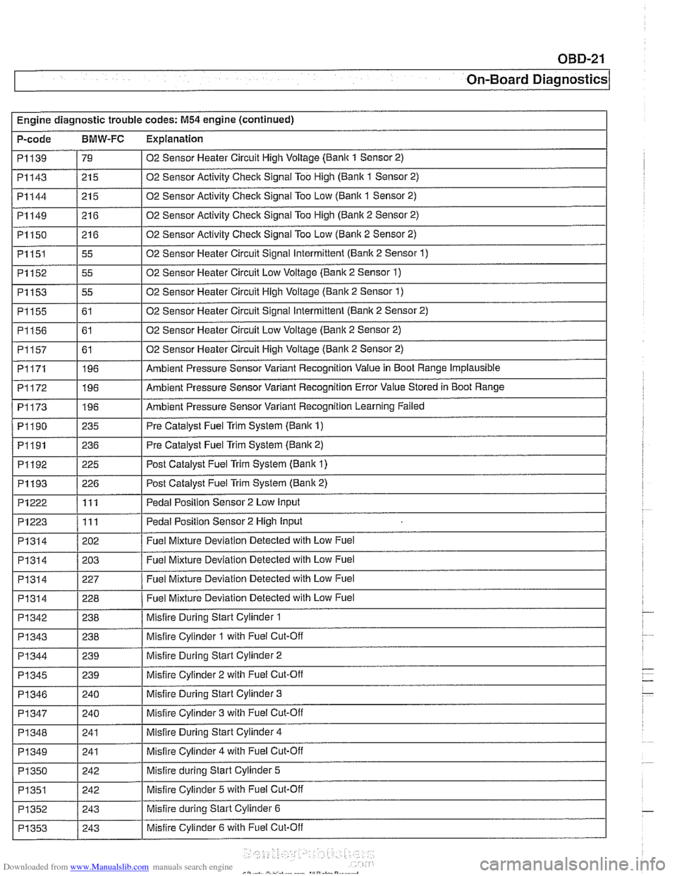
OBD-21
On-Board
~ia~nosticsl
Engine diagnostic trouble codes: M54 engine (continued)
P-code
BMW-FC Explanation
I I
PI314 / 202 / Fuel Mixture Deviation Detected with Low Fuel
I I
02 Sensor Heater Circuit High Voltage (Bank 1 Sensor 2)
02 Sensor Activity Check Signal Too High (Banlc 1 Sensor 2)
02 Sensor Activity Check Signal Too Low (Bank 1 Sensor 2)
02 Sensor Activity Check Signal Too High (Banlc 2 Sensor 2)
02 Sensor Activity Check Signal Too Low (Bank 2 Sensor 2)
02 Sensor Heater Circuit Signal Intermittent (Bank 2 Sensor
1)
02 Sensor Heater Circuit Low Voltage (Bank 2 Sensor 1)
02 Sensor Heater Circuit High Voltage (Bank 2 Sensor 1)
02 Sensor Heater Circuit Signal Intermittent (Banlc 2 Sensor 2)
02 Sensor Heater Circuit Low Voltage (Bank 2 Sensor 2)
02 Sensor Heater Circuit High Voltage (Bank 2 Sensor 2)
Ambient Pressure Sensor Variant Recognition Value in Boot Range Implausible
Ambient Pressure Sensor Variant Recognition Error Value Stored in Boot Range
Ambient Pressure Sensor Variant Recognition Learning Failed
Pre Catalyst Fuel Trim System (Bank 1)
Pre Catalyst Fuel Trim System (Bank 2)
PI139
PI143
PI144
PI149
PI150
PI151
PI152
PI153
PI155
P1156
PI157
PI171
PI172
PI173
PI 190
PI191
79
21 5
21 5
21 6
21 6
55
55
55
61
61
61 196
196
196
235
236
Pedal Position Sensor 2 Low
Input PI222
-~~~~~~~~~ PI314
PI314
PI314
PI342 - PI343
PI 344
PI192
PI193
PI223 /I11 I Pedal Position Sensor 2 High Input
111
PI 345
PI 346
PI 347
PI348
PI 349
PI350
PI351
PI352
PI353
225 Post Catalyst Fuel Trim System (Bank 1)
226 Post Catalyst Fuel Trim Svstem (Bank 2)
203
227
228
238
238
239 Fuel Mixture Deviation Detected with Low Fuel
Fuel Mixture Deviation Detected with Low Fuel
Fuel Mixture Deviation Detected with Low Fuel
Misfire During Start Cylinder 1
Misfire Cylinder 1 with Fuel Cut-Off
Misfire Durina Start Cylinder 2
239
240
240
241
241
242
242
243
243
-
Misfire Cylinder 2 with Fuel Cut-Off
Misfire During Start Cylinder 3
Misfire Cylinder 3 with Fuel Cut-Off
Misfire During Start Cylinder 4
Misfire Cylinder 4 with Fuel Cut-Off
Misfire during Start Cylinder 5
Misfire Cylinder 5 with Fuel Cut-Off
Misfire during Start Cylinder 6
Misfire Cylinder 6 with Fuel Cut-Off