Ignition systems BMW 528i 2000 E39 User Guide
[x] Cancel search | Manufacturer: BMW, Model Year: 2000, Model line: 528i, Model: BMW 528i 2000 E39Pages: 1002
Page 379 of 1002
Downloaded from www.Manualslib.com manuals search engine
Battery, Starter, ~lternatorl
Charging system quick-check
Use a digital multimeter to measure voltage across the bat-
tery terminals with key off and then again with engine running.
Battery voltage should be about 12.6 volts with key off and be-
tween 13.5 and 14.5 volts with engine running.
NOTE-
The regulated voltage (engine running) should be between
13.2 and 14.5, depending on temperature andoperating con-
ditions.
If the voltage is higher than 14.8, the voltage regula-
tor or
mulitfunction controller is most likely faulty
Check for clean and tight battery cables. Check ground cable
running from negative
(-) battery terminal to chassis and
ground cable running from engine to chassis. Check alterna-
tor drive belt condition and tension.
Charging system, checking
CAUTIOI\C
* Do not disconnect the battery while the engine is running.
Damage to the alternator and/or engine electronic systems
may result.
Only use a digital multimeter when testing charging
system components.
--7
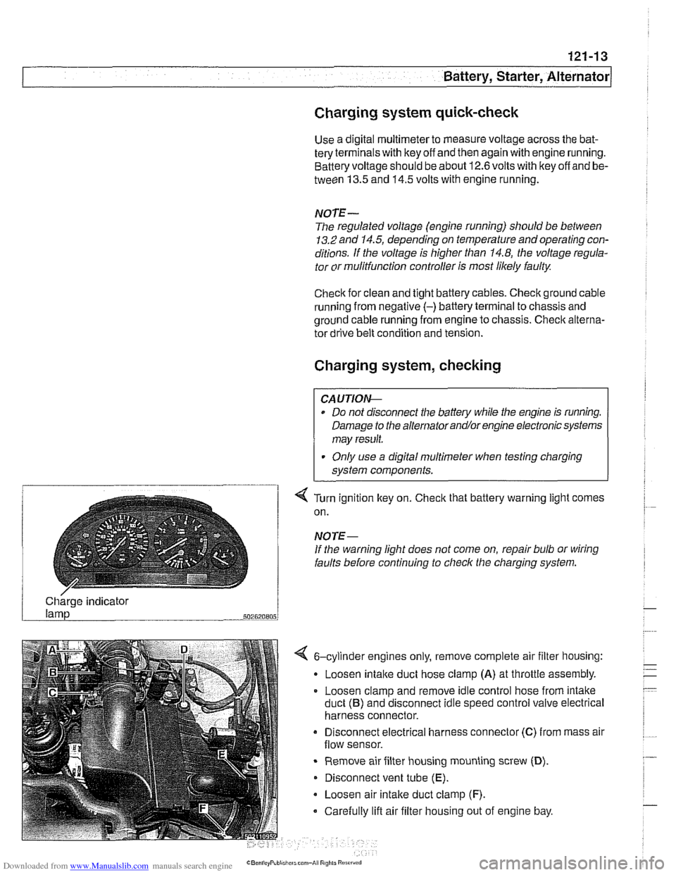
4 Turn ignition key on. Check that battery warning light comes
on.
NOTE-
If the warning light does not come on, repair bulb or wiring
faults before continuing to checlc the charging system.
/ Charge indicator
502820805
4 6-cylinder engines only, remove complete air filter housing:
Loosen
intake duct hose clamp (A) at throttle assembly.
Loosen clamp and remove idle control hose from intake
duct
(B) and disconnect idle speed control valve electrical
harness connector.
Disconnect electrical harness connector
(C) from mass air
flow sensor.
Remove air filter housing mounting screw
(D).
Disconnect vent tube (E).
Loosen air intake duct clamp (F).
Carefully lift air filter housing out of engine bay.
Page 392 of 1002
Downloaded from www.Manualslib.com manuals search engine
130-2
/Fuel Injection
This repair group covers service and repair of the Bosch and
Siemens engine management systems used on
1997
through 2002 E39 models. Additional engine management
service and repair information may also be found in the fol-
lowing repair groups:
0 020 Maintenance
120 Ignition System
160 Fuel Tank and Fuel Pump
610 Electrical Component Locations
OBD On Board Diagnostics
NOTE-
Camshaft position sensor, crankshaft speed sensor and
knoclc sensors are covered in 120 Ignition System.
Table a. Engine management system applications
- - ~ ~
1 ~odellmodel year / Engine IDME system I - I
5281, 1997-1 998 IM52. 2.8 liter ISiemens MS 41 .I I 1
528i. 1999ZO00 1~52 TU, 2.8 liter ]siemens MS 42.0 I I
5251, 2001-2002 1~54, 2.5 liter 1 Siemens MS 43.0 I I
530i, 2001-2002 1~54, 3.0 liter ISiemens MS 43.0
5401 1999-2001 1~62 TU, 4.4 liter l~osch ME 7.2
I
OBI) II software and hardware is incorporated in the engine
management control systems. The
OED II system monitors
components that influence exhaust and evaporative emis-
sions. If a problem is detected, the
OED I1 system stores the
associated fault code and condition.
540i. 1997
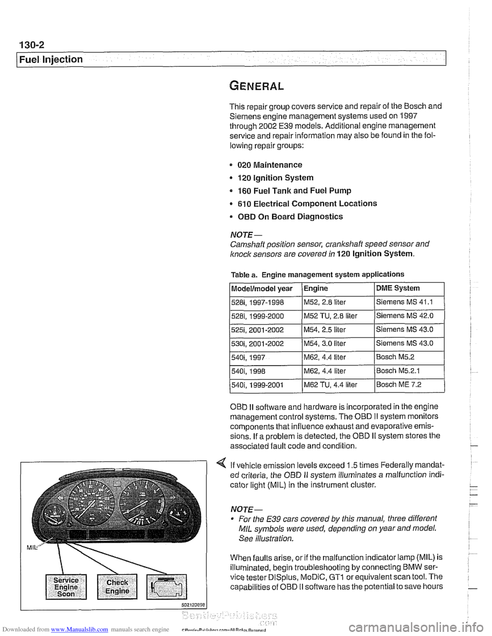
4 If vehicle emission levels exceed 1.5 times Federally mandat-
ed criteria, the
OED II system illuminates a malfunction indi-
cator light
(MIL) in the instrument cluster.
For the
E39 cars covered by this manual, three different
MIL symbols were used, depending on year and model.
See illustration.
When faults arise, or if the malfunction indicator lamp (MIL) is
illuminated, begin troubleshooting by connecting BMW ser-
vice tester
DISplus, MoDiC, GTl or equivalent scan tool. The
capabilities of OBD
II software has the potential to save hours
540i. 1998 IM62, 4.4 liter /Bosch M5.2.1
M62, 4.4 liter Bosch M5.2
Page 417 of 1002
Downloaded from www.Manualslib.com manuals search engine
-
Fuel Injection
ECM relay, testing
The engine control module (ECM) relay is energized via the
ECM and supplies battery positive
(Bc) power to many of the
engine management components and subsystems. If this re-
lay is faulty, the engine will not start.
NOTE-
The ECM relay is also referred to as the DME main relay
ECM relay powers:
ECM
Ignition coils
* Fuel injection
Evaporative leak detection pump
Idle air actuator
- Camshaft sensors Evaporative emissions valve
Hot film mass air flow sensor
Fuel pump relay
Oxygen sensor heaters
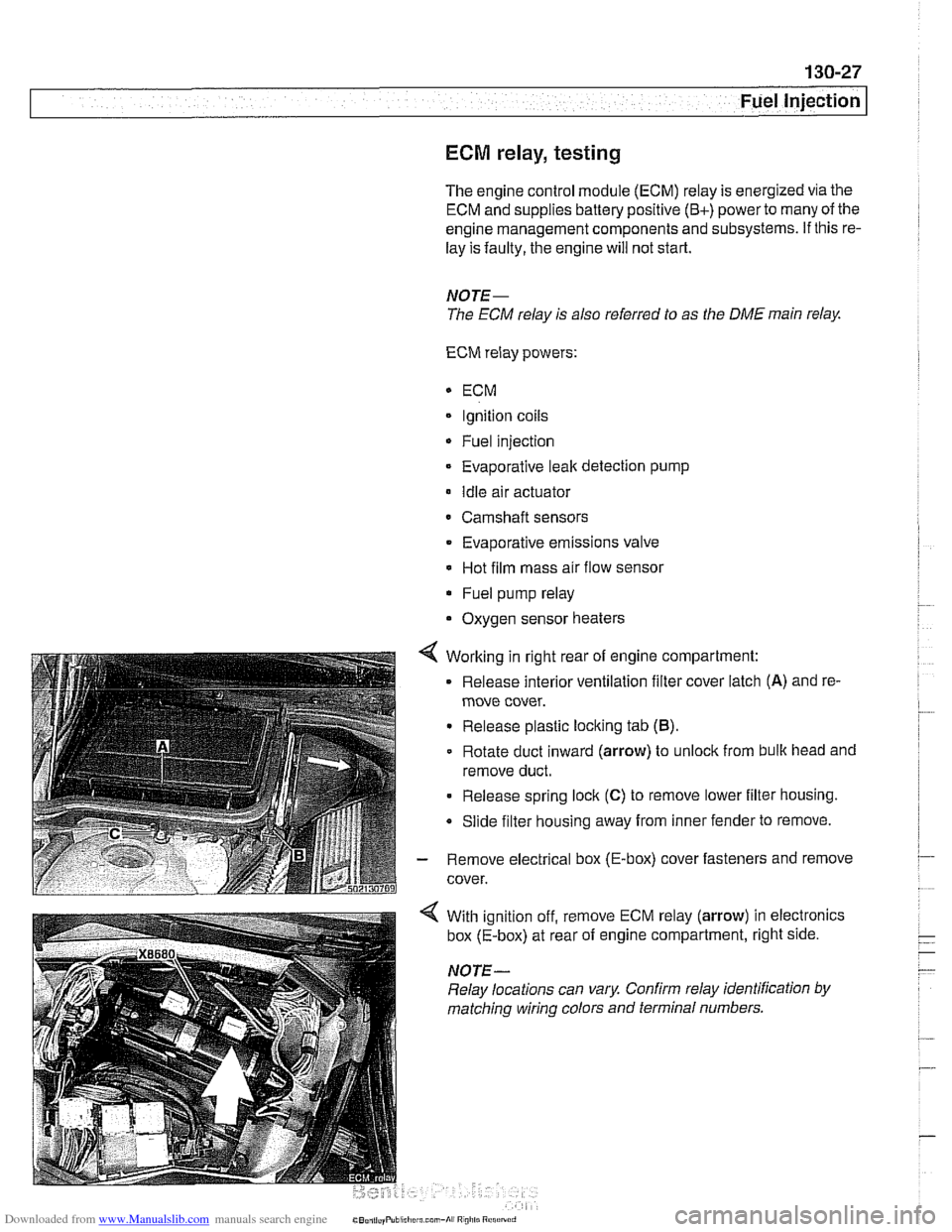
4 Working in right rear of engine compartment:
Release interior ventilation filter cover latch
(A) and re-
move cover.
Release plastic locking tab
(B).
Rotate duct inward (arrow) to unlock from bulk head and
remove duct.
Release spring lock
(C) to remove lower filter housing.
Slide filter housing away from inner fender to remove.
- Remove electrical box (E-box) cover fasteners and remove
cover.
With ignition off, remove ECM relay (arrow) in electronics
box (E-box) at rear of engine compartment, right side.
NOTE-
Relay locations can vary Confirm relay identification by
matching wiring colors and terminal numbers.
Page 439 of 1002
Downloaded from www.Manualslib.com manuals search engine
- Fuel Injection
ECM relay, testing
The engine control module (ECM) relay is energized via the
ECM and supplies battery positive
(B+) power to many of the
engine
management components and subsystems. If this re-
lay is faulty, the engine will not start.
CAUTIOI\C
Relay positions can vary. Be sure to confirm relay position by
identifying the wiring
in the socket using the wiring diagrams
in ELE Electrical Wiring Diagrams.
NOTE-
The ECM relay is also referred to as the DME main relay.
ECM relay powers:
* ECM
Ignition coils
Fuel injection
Evaporative leak detection pump
(5.2.1 only)
Idle air actuator
Camshaft sensors Evaporative emissions valve
Hot film mass air flow sensor
Fuel pump relay
Oxygen sensor heaters
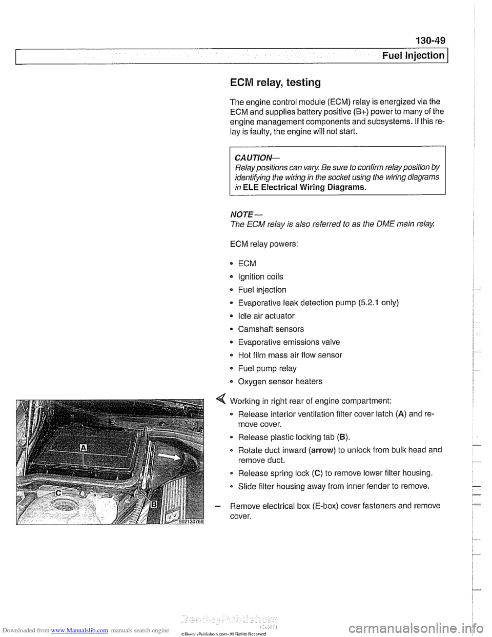
4 Working in right rear of engine compartment:
Release interior ventilation filter cover latch
(A) and re-
move cover.
Release plastic locking tab
(B).
Rotate duct inward (arrow) to unloclc from bulk head and
remove duct.
0 Release spring lock (C) to remove lower filter housing.
Slide filter housing away from inner fender to remove.
- Remove electrical box (E-box) cover fasteners and remove
cover.
Page 459 of 1002
Downloaded from www.Manualslib.com manuals search engine
--
Fuel Injection I
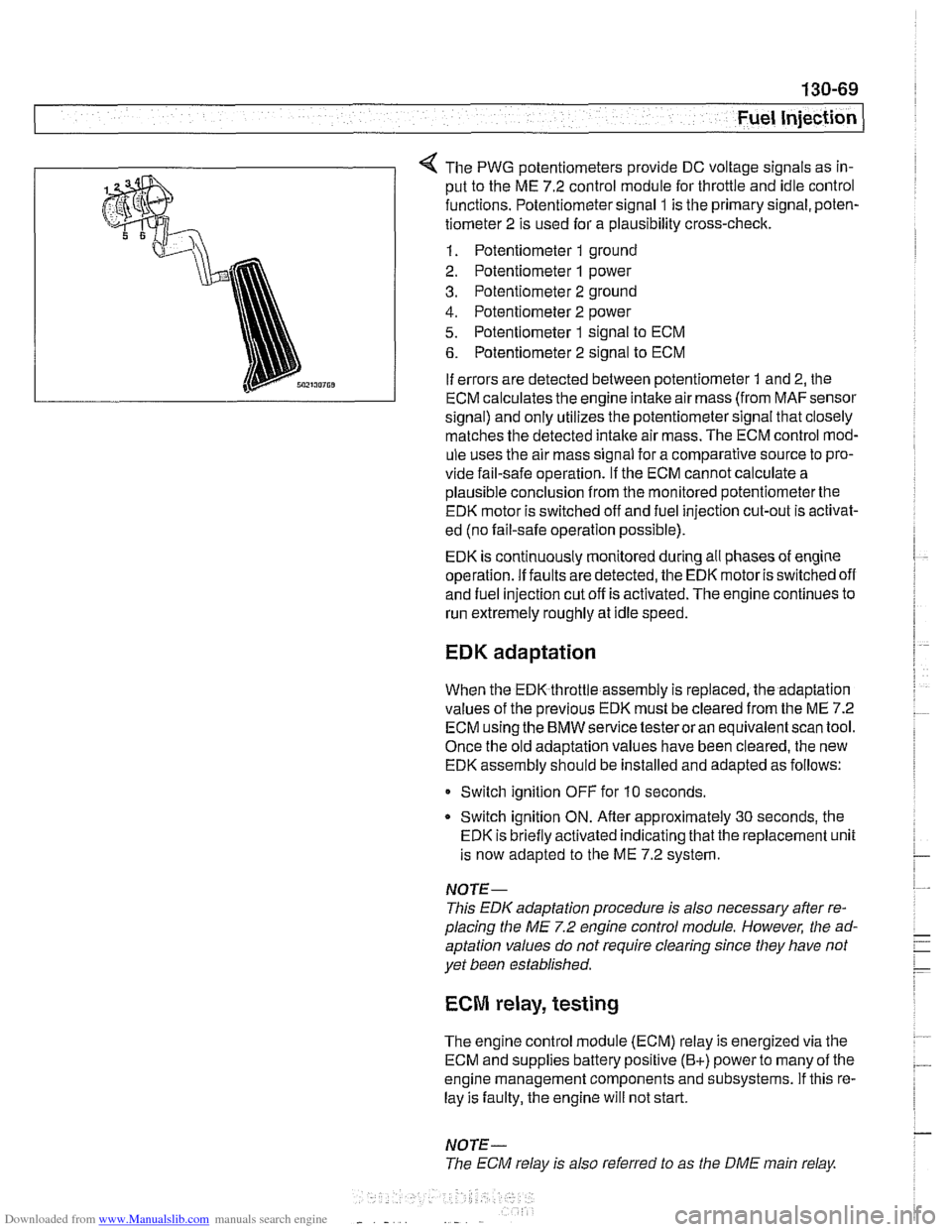
The PWG potentiometers provide DC voltage signals as in-
put to the ME 7.2 control module for throttle and idle control
functions. Potentiometer signal
1 is the primary signal, poten-
tiometer 2 is used for a plausibility cross-check.
1. Potentiometer 1 ground
2. Potentiometer
1 power
3. Potentiometer 2 ground
4. Potentiometer 2 power
5. Potentiometer 1 signal to ECM
6. Potentiometer 2 signal to ECM
If errors are detected between potentiometer
1 and 2, the
ECM calculates the engine intake air mass (from
MAFsensor
signal) and only utilizes the potentiometer signal that closely
matches the detected
intake air mass. The ECM control mod-
ule uses the air mass signal for a comparative source to pro-
vide fail-safe operation.
If the ECM cannot calculate a
plausible conclusion from the monitored potentiometerthe
EDK motor is switched off and fuel injection cut-out is activat-
ed (no fail-safe operation possible).
EDK is continuously monitored during all phases of engine
operation. If faults are detected, the EDK motor is switched off
and fuel injection cut off is activated. The engine continues to
run extremely roughly at idle speed.
EDK adaptation
When the EDK throttle assembly is replaced, the adaptation
values of the previous EDK must be cleared from the ME 7.2
ECM using the BMW service testeroran equivalentscan tool.
Once the old adaptation values have been cleared, the new
EDK assembly should be installed and adapted as follows:
0 Switch ignition OFF for 10 seconds.
* Switch ignition ON. Afler approximately 30 seconds, the
EDK is briefly activated indicating that the replacement unit
is now adapted to the ME 7.2 system.
NOTE-
This EDK adaptation procedure is also necessary after re-
placing the
ME 7.2 engine control module. However, the ad-
aptation values do not require clearing since they have not
yet been established.
ECM relay, testing
The engine control module (ECM) relay is energized via the
ECM and supplies battery positive
(B+) power to many of the
engine management components and subsystems. If this re-
lay is faulty, the engine will not start.
NOTE-
The ECM relay is also referred to as the DME main relay
Page 792 of 1002
Downloaded from www.Manualslib.com manuals search engine
1 Brakes
- Remove precharge pump mounting bracket fasteners and re-
move pump.
- Installation is reverse of removal, noting the following:
Be sure to replace rubber pump mounts if damaged
01
worn.
Bleed brakes as described earlier.
Tightening torque Brake line
to precharge pump 18 Nrn (13 ft-lb)
DSC pressure sensor (1 999 - 2002 models)
On 1999 and later DSC systems, the DSC pressure sensor is
screwed into the DSC hydraulic unit (right rear of engine com-
partment).
WARNING-
* €39 cars require special BMW service equipment to prop-
erly bleed the brakes. Removal of the
DSCpressure sensor
is not recommended unless this equipment is available. For
safety reasons, the brake system on cars with ABS must be
bled using the procedures described in this repair group.
Switch off ignition and remove
key to male sure brake
system cannot be activated.
- Disconnect electrical harness connector at switch.
- Use BMW special tool 34 5 160 to remove and install sensor.
Inspect threads and sealing surfaces for damage.
* Work quicltly to avoid excessive brake fluid leakage.
Tightening torque
Pressure sensor
to hydraulic 19 Nrn (14ft-lb)
unit
- Reconnect harness connector
- Bleed front brakes as described earlier.
- Press on brakes and check for leaks at sensor.
- Turn on ignition and firmly depress brake pedal. Check that
DSC warning light does not come on.
Page 994 of 1002
Downloaded from www.Manualslib.com manuals search engine
4 INDEX
Door window anti-trap
512-4 convenience openinglclosing 512.4
regulator and motor 512-1 1
service
512-5 switches 512-3
see also Switches
Double
VANOS see VANOS
Drive
axle
CV joint 331-15 CV joint boot 331-15
rernovinglinstalling 331-14
Drive belt
see Maintenance
Driveabiiity troubleshooting
100-4
Driveaway protection
see EWS (eiectronic immobilization)
Driveshaft aligning
260-7
center bearing, replacing 260-12 CV joint, replacing 260-14
itex-disc, replacing 260-1 1
iront centering guide, replacing 260-13
rernovinglinstailing 260-6
lroubleshooting 260-3
U-joint 260-3
DSC
see Braires
DTC (diagnostic trouble code)
OBD-8
DWA
see Anti-theft alarm
ECM (engine control module)
see 130 under appropriate
iuei
injection system
ECT (engine coolant temperature)
sensor see 130 under appropriate
iuei
injection system
EDK adaptation
130-69
MS 43.0 130-35
EHC see Electronic iieigiit control (EHC)
Electric cooling fan
see Cooling system, cooling
fan
see also Cooiing system, eiectric fan
Electrical switches
see Switches
Electrical system abbreviations
600-14 bus System 600-4
component location table 610-3
components
photos
610-36
Sport Wagon 610-81 engine 121-2
troubleshooting 600-15
voltage and polarily 600-5 wire color codes 600-12
wiring diagrams 600-12
Electrical wiring diagrams
ELE-1
Eiectricaliy heated thermostat
(characteristic map)
170-4
Eiectronic height control (EHC)
300-8, 330-44
Eiectronic immobilization
see EWS (electronic immobilization)
Eiectronics box
(E-box)
610-37
Emergencies
010-18
Emergency brake see
BraBes, parking brake Engine
see also Cylinder head and valvetrain
applications
100-2
compression, testing 113-5
cooling see Cooiing system
crankshaft front oil seai
see Crankshaft oil seals
cyiinder leak-down test 113-8
diagnostic testing 113-1
drive belts
see Maintenance
driveability troubleshooting
100-4
engine management systems 100-2
see also Ignition
see also Fuel injection
fuel supply
130-6
ground connections 100-5
see also 61 0 identilying ieatures 100-3
lubrication svstem
see
~ubricetion system
mount
on-board diagnostics
OBD-I
oxygensensor
see Fuel injection
see also Exhaust system
Dreventive maintenance
see Maintenance
removal/installation
Engine control module (ECM)
see 130 under appropriate iuel
injection system
Engine cooiant temperature (ECT)
sensor see 130 under appropriate iuel
injection
system
Engine cooling fan
see Cooiing system, electric fan
Engine hood
41
0-6 raising to service position 410-6
Engine troubleshooting
see Engine, driveability troubleshooting
EVa~oratiVe control svstem
160-3 see also 130 under aDDroDriate iuel
injection system
Evaporator see
NC
Evaporator temperature sensor see
NC