compressor BMW 528i 2000 E39 User Guide
[x] Cancel search | Manufacturer: BMW, Model Year: 2000, Model line: 528i, Model: BMW 528i 2000 E39Pages: 1002
Page 455 of 1002
Downloaded from www.Manualslib.com manuals search engine
Fuel Injection
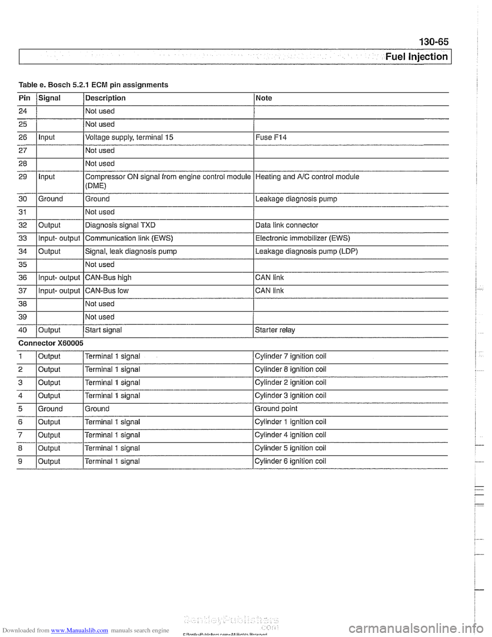
Table Pin
24
25
26
27
28
29
30
31
32
33
34
35
36
37
38
39
40
1
2
3
4
5
6
7
8
9
e. Bosch 5.2.1
Signal
Input
Input
Ground
Output Input- output
Output
Input- output
Input- output
Output
Connector
X60005
Output
Output
Output
Output
Ground
Output
Output
Output
Output
ECM pin assignments
Description
Not used
Not used
Voltage supply, terminal
15
Not used
Not used
Compressor ON signal from engine control module
(DME)
Ground
Not used
Diagnosis signal TXD
Communication
link (EWS)
Signal, leak diagnosis pump
Not used
CAN-Bus high
CAN-Bus low Not used
Not used
Start
signal
Terminal 1 signal
Terminal
1 signal
Terminal
1 signal
Terminal
1 signal
Ground
Terminal
1 signal
Terminal
1 signal
Terminal
1 signal
Terminal 1 signal Note
Fuse
F14
Heating
and AIC control module
Lealtage diagnosis pump
Data
iinit connector
Electronic immobilizer (EWS)
Leakage diagnosis pump (LDP)
CAN link
CAN link
Starter relay
Cylinder
7 ignition coil
Cylinder 8 ignition coil
Cylinder
2 ignition coil
Cylinder
3 ignition coil
Ground point
Cylinder
1 ignition coil
Cylinder
4 ignition coil
Cylinder 5 ignition coil
Cylinder
6 ignition coil
Page 469 of 1002
Downloaded from www.Manualslib.com manuals search engine
Fuel Injection I
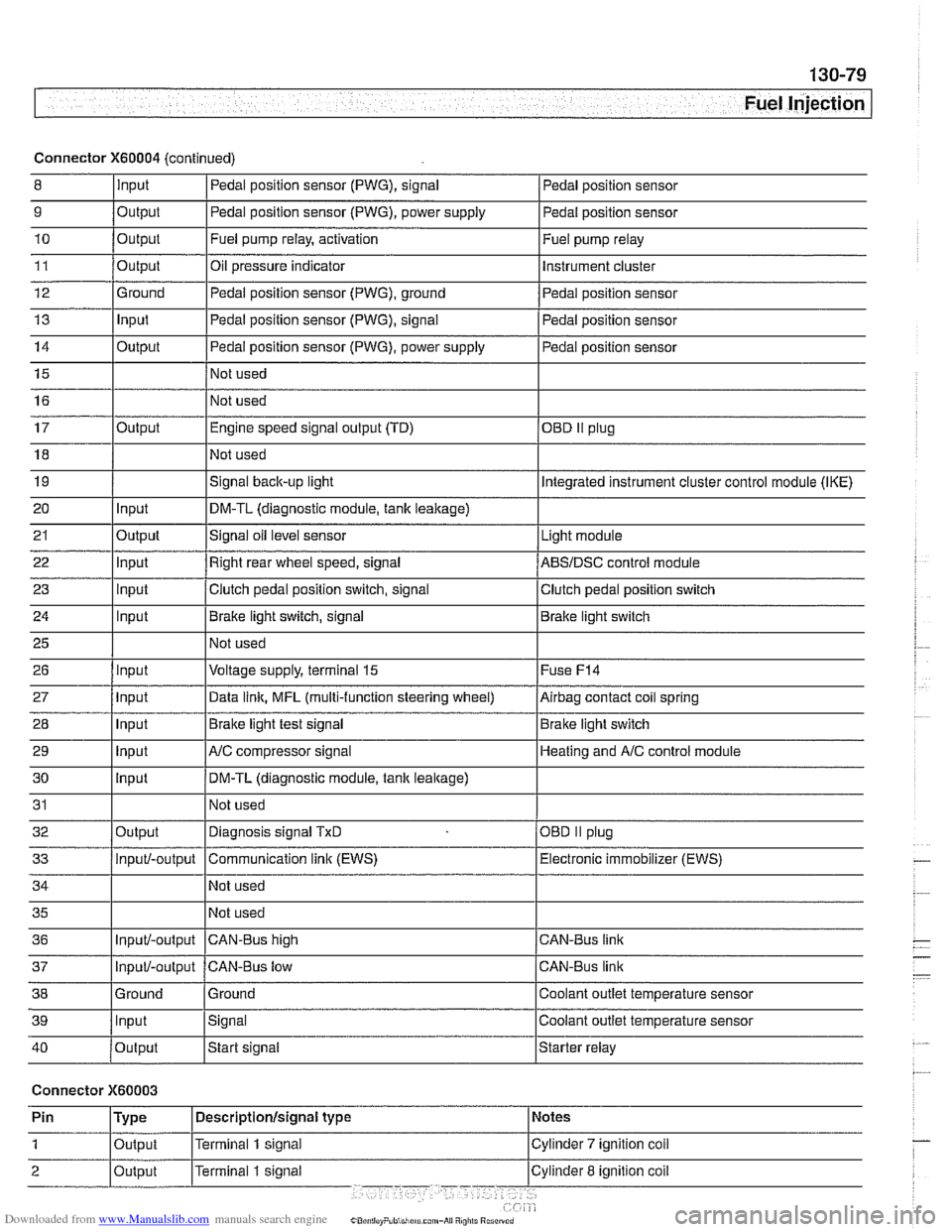
Connector X60004 (continued)
8 10
11
12
13
14
15
16
9
Output 0
Input
17
18
19
20
21
22
23
24
25
26
27
28
29
30
31
32
33
34
35
36
39
llnput lsignal l~oolant outlet temperature sensor
Output
Output
Ground
Input
Output
I I - I
40 /output Istart signal Istarter relay
Pedal position sensor (PWG), signal
Output Input
Output
input
Input
Input
Input
Input
Input
input
Input
Output
Input/-output
Input/-output
37
Connector X60003
Pedal position sensor
Fuel pump relay, activation
Oil pressure indicator Pedal position sensor (PWG), ground
Pedal position sensor (PWG), signal
Pedal position sensor (PWG), power supply
Not used
Not used Fuel
pump relay
Instrument cluster
Pedal position sensor
Pedal position sensor
Pedal position sensor
Engine speed signal output (TD)
Not used
Signal
back-up light
DM-TL (diagnostic module,
tank leakage)
Signal oil level sensor
Right rear wheel speed, signal
Clutch pedal position switch, signal
Brake light switch, signal
Not used
Voltage supply, terminal
15
Data link, MFL (multi-function steering wheel)
Brake light test signal
AJC compressor signal
DM-TL (diagnostic module, tank
leakage)
Not used
Diagnosis signal
TxD
Communication link (EWS)
Not used
Not used
CAN-BUS hiqh
38 1 Ground l~round I Coolant outlet temperature sensor
OED II plug
Integrated instrument cluster control module (IKE)
Light module
ABSIDSC control module
Clutch pedal position switch
Brake light switch
Fuse
F14
Airbag contact coil spring
Brake light switch
Heating and
A/C control module
OBD
II plug
Electronic immobilizer (EWS)
CAN-Bus link
CAN-Bus link
Input/-output CAN-Bus low
Page 639 of 1002
Downloaded from www.Manualslib.com manuals search engine
Front Suspension
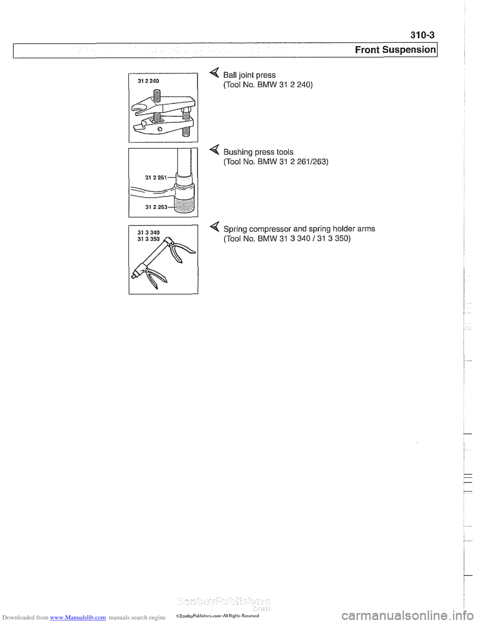
< Ball joint press
(Tool No. BMW
31 2 240)
< Bushing press tools
(Tool No. BMW
31 2 2611263)
4 Spring compressor and spring holder arms
31 3 350 (Tool No. BMW 31 3 340 131 3 350)
Page 646 of 1002
Downloaded from www.Manualslib.com manuals search engine
31 0-1 0
Front Suspension
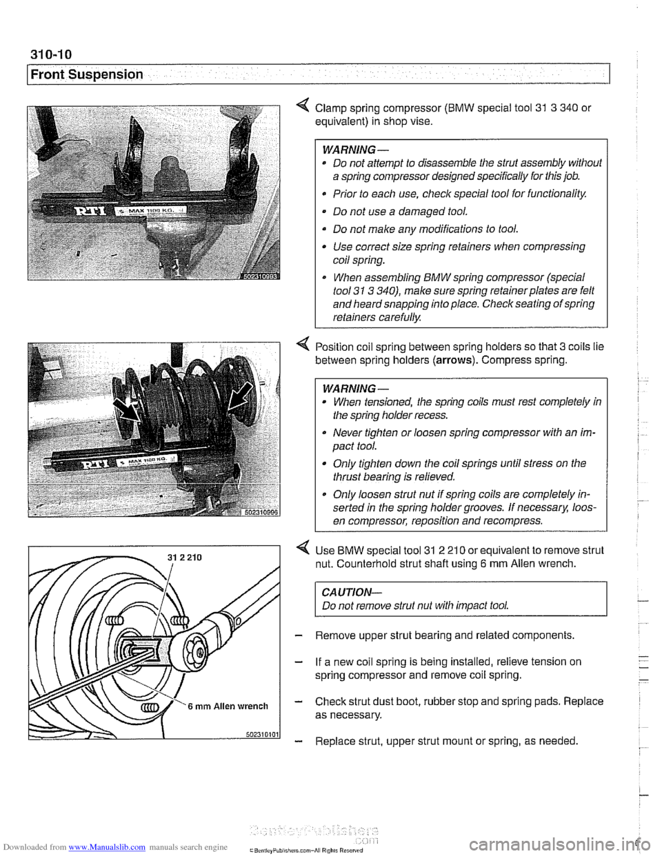
4 Clamp spring compressor (BMW special tool 31 3 340 or
equivalent) in shop vise.
WARNING-
* Do not attempt to disassemble the strut assembly without
a spring compressor designed specifically for this job.
Prior to each use,
checlc special tool for functionality.
Do not use a damaged tool.
Do not make any modifications to tool. Use correct size spring retainers when compressing
coil spring.
I When assembling BMW spring compressor (special
tool
31 3 340), make sure spring retainerplates are felt
and heard snapping into place. Check seating of spring
retainers carefully.
Position coil spring between spring holders so that
3 coils lie
between spring holders
(arrows). Compress spring.
WARNING -
When tensioned, the spring coils must rest completely in
the spring holder recess.
Never tighten or loosen spring compressor with an im-
pact tool.
Only tighten down the coil springs until stress on the
thrust bearing is relieved.
a Only loosen strut nut if spring coils are completely in-
serted in the spring holder grooves. If
necessarx loos-
en compressor, reposition and recompress.
Use
BMW special tool 31 2 21 0 or equivalent to remove strut
nut. Counterhold strut shaft using
6 mm Allen wrench.
CAUTION-
Do not remove strut nut with impact tool.
Remove upper strut bearing and related components.
If a new coil spring is being installed, relieve tension on
spring compressor and remove coil spring.
Check strut dust boot, rubber stop and spring pads. Replace
as necessary.
Replace strut, upper strut mount or spring, as needed
Page 647 of 1002
Downloaded from www.Manualslib.com manuals search engine
Front Suspension
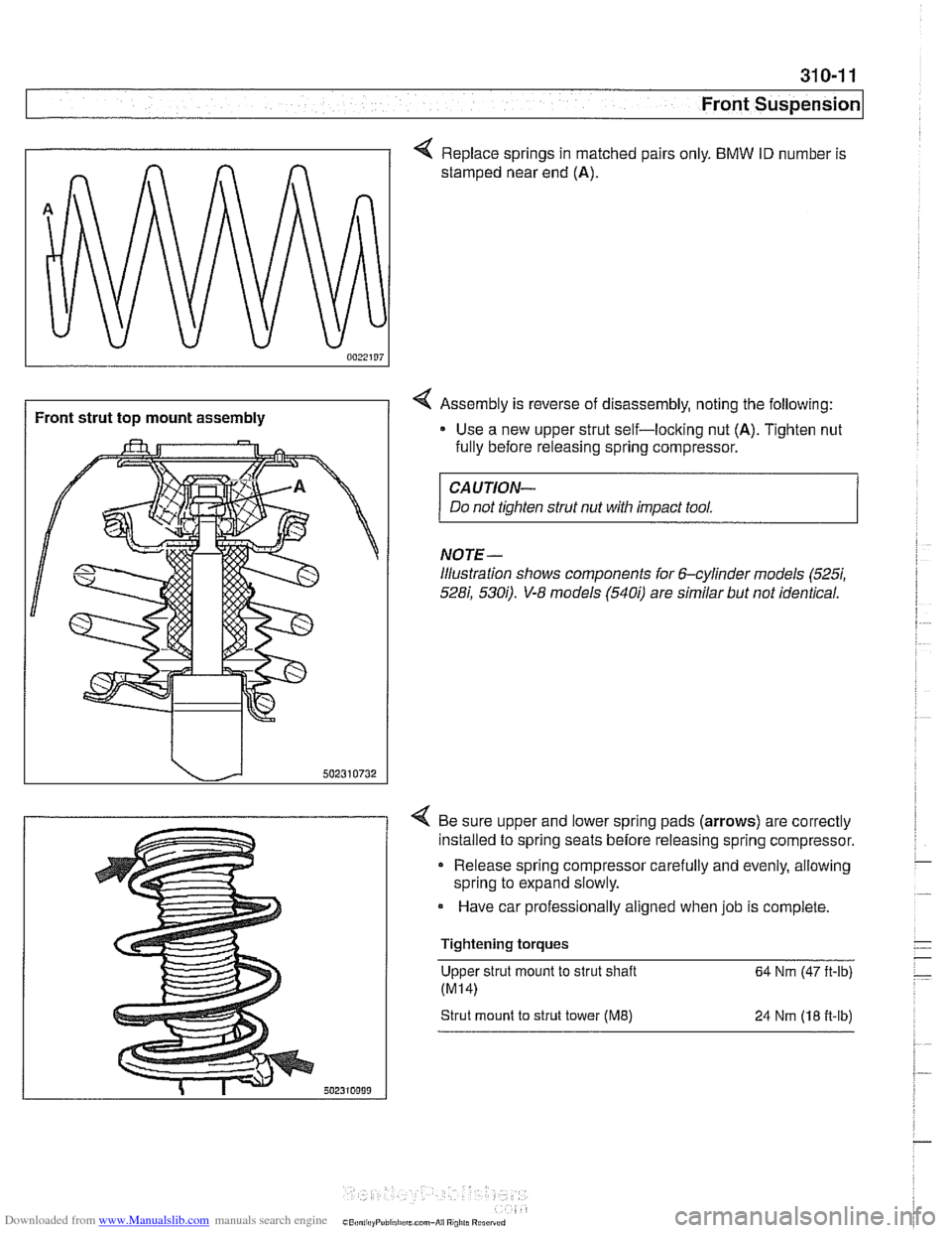
/ Front strut top mount assembly
< Replace springs in matched pairs only. BMW ID number is
stamped near end
(A).
4 Assembly is reverse of disassembly, noting the following:
Use a new upper strut self-loclting nut
(A). Tighten nut
fully before releasing spring compressor.
CAUTION-
Do not tighten strut nut with impact tool.
NOTE-
illustration shows components for 6-cylinder models (5257,
528i, 5300. V-8 models (5400 are similar but not identical.
4 Be sure upper and lower spring pads (arrows) are correctly
installed to spring seats before releasing spring compressor.
Release spring compressor carefully and evenly, allowing
spring to expand slowly.
Have car professionally aligned when job is complete.
Tightening torques Upper strut mount to strut shaft
64 Nm (47 ft-lb)
Strut mount to strut tower (ME) 24 Nrn (18 fi-lb)
Page 697 of 1002
Downloaded from www.Manualslib.com manuals search engine
330 Rear Suspension
General . . . . . . . . . . . . . . . . . . . . . . . . . . . ,330-2
Special tools . . . . . . . . . . . . . . . . . . . . . . . . ,330-2
Rear suspension variations . . . . . . . . . . . . ,330-4
Rear Struts and Springs
(sedan models)
. . . . . . . . . . . . . . . . . . . . ,330-5
Rear strut assembly, removing
and installing
. . . . . . . . . . . . . . . . . . . . . . . ,330-5
Rear strut assembly, disassembling
and assembling
. . . . . . . . . . . . . . . . . . . . . ,330-7
Rear Shock Absorbers and
Springs (Sport Wagon models)
. . . . . ,330-9
Rear shock absorber, removing
and installing
. . . . . . . . . . . . . . . . . . . . . . . ,330-9
Coil spring, removing and installing . . . . . ,330-1 1
Air spring, removing and installing
. . . . . . ,330-12
Rear Suspension Arms,
Subframe and Bushings . . . . . . . . . . ,330-13
Rear suspension arm components . . . . . . ,330-1 3
Swing arm, removing and installing (sedan models)
. . . . . . . . . . . . . . . . . . . . . ,330-1 4
Swing arm, removing and installing (Sport Wagon models)
. . . . . . . . . . . . . . . ,330-16
Swing arm ball joint, replacing . . . . . . . . . ,330-1 9
Upper rear control arm, removing
and installing (sedan models)
. . . . . . . . . . .330-22
Upper rear control arm, removing
and installing (Sport Wagon models)
. . . . .330-23
Upper front control arm (traction strut),
removing and installing
. . . . . . . . . . . . . . . ,330-25
Rear axle assembly, removing and
installing (sedan models)
. . . . . . . . . . . . . ,330-26
Rear axle assembly, removing and
installing (Sport Wagon models)
. . . . . . . ,330-28
Rear subframe mounting bushings,
removing and installing
. . . . . . . . . . . . . . . .330-31
Rear Wheel Bearings . . . . . . . . . . .
Rear wheel bearing carrier, removing
and installing (sedan models)
. . . . . . .
Rear wheel bearing carrier, removing
and installing (Sport Wagon models)
. .
Rear wheel bearing, replacing . . . . . . .
Rear Stabilizer Bar
Stabilizer bar, removing and installing .
Stabilizer bar link, removing
and installing
. . . . . . . . . . . . . . . . . . . .
Electronic Height Control (EHC)
Component Replacement
. . . . . . .
Electronic height control (EHC)
components
.....................
Air compressor pump relay, removing
and installing
. . . . . . . . . . . . . . . . . . . .
EHC control module, removing
and installing
. . . . . . . . . . . . . . . . . . . .
Air supply unit, removing and installing
Ride height sensor, removing
and installing
. . . . . . . . . . . . . . . . . . . .
Page 698 of 1002
Downloaded from www.Manualslib.com manuals search engine
330-2
I Rear Suspension
This repair group covers removal and replacement of E39
rear suspension components. A general description of sus-
pension systems and ride height specifications can be found
in 300 Suspension, Steering and Brakes - General.
CAUTIOI\C
Some E39 models are equipped with aluminum suspen-
sion components. The following cautions apply:
Due to the chemical and corrosion characteristics of
aluminum, do not bring into contact with battery acid.
- Do not clean with wire brushes with brass or iron bris-
tles. Only use brushes with stainless steel bristles.
Do not expose to flying
sparl~s from grinding/cutting op-
erations.
* Do not subject to steel welding splashes.
0 Do not expose to temperatures over 80°C (176°F).
even for shortperlods. Temperatures in painting facili-
ties are not a problem.
Special tools
Special service tools are required for some of the work de-
scribed in this repair group. Most of these tools are special-
ized press jigs and pullers that might be replaced by standard
pullers of various sizes.
Read the procedures through before beginning any job.
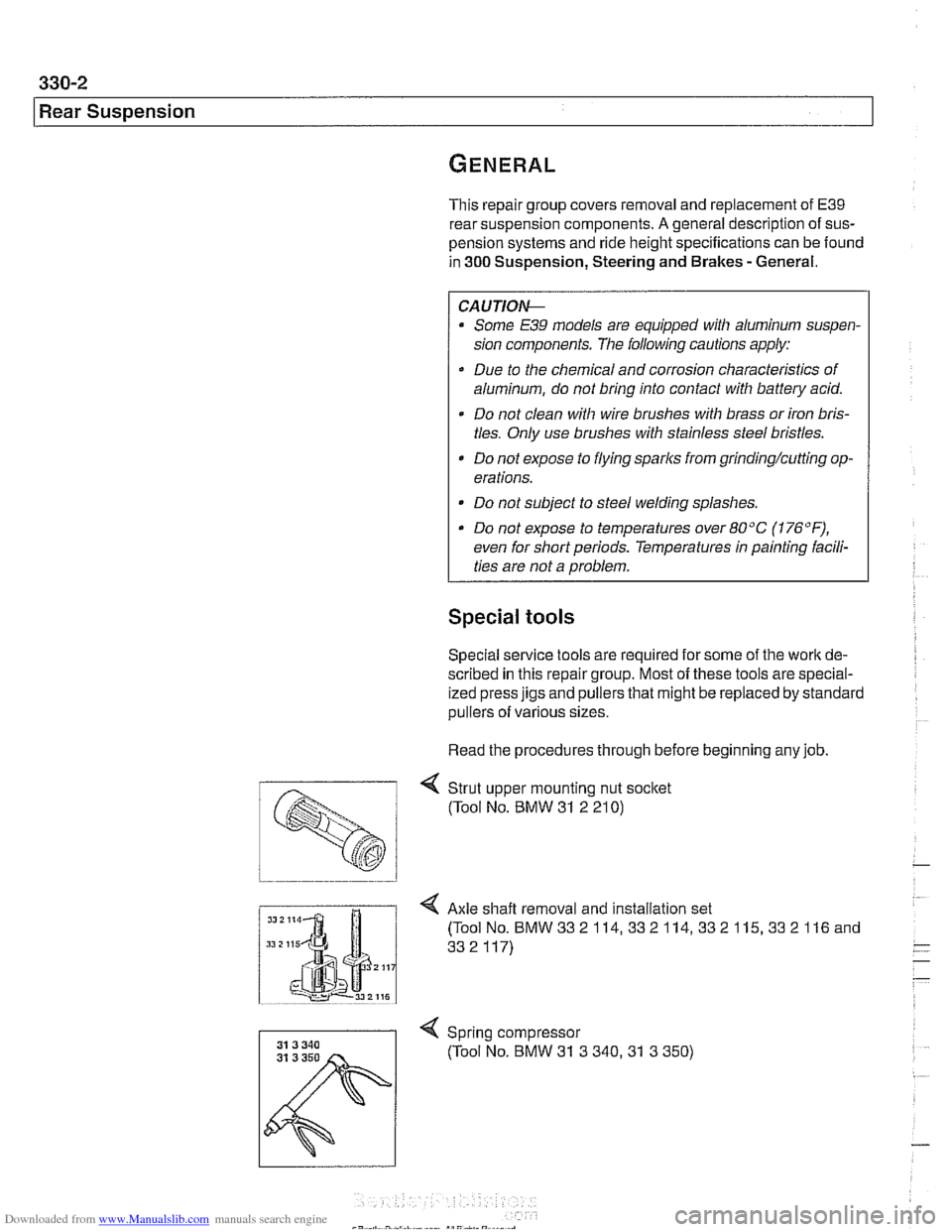
< Strut upper mounting nut socket
(Tool No. BMW
31 2 21 0)
I Axle shaft removal and installation set
Spring compressor (Tool No. BMW
31 3 340.31 3 350)
Page 703 of 1002
Downloaded from www.Manualslib.com manuals search engine
Rear ~us~ensionl
Rear strut assembly, disassembling and
assembling
Replace struts and coil springs in pairs only
Replacing the upper strut mount, spring or strut requires that
the strut assembly first be removed from the car, as described
earlier. Strut disassembly requires a spring compressor.
WARNING-
Do not attempt to disassemble the strut without a spring com-
pressor designed specifically for the job.
- Remove strut assembly from car as described in Rear strut
assembly, removing
bnd installing
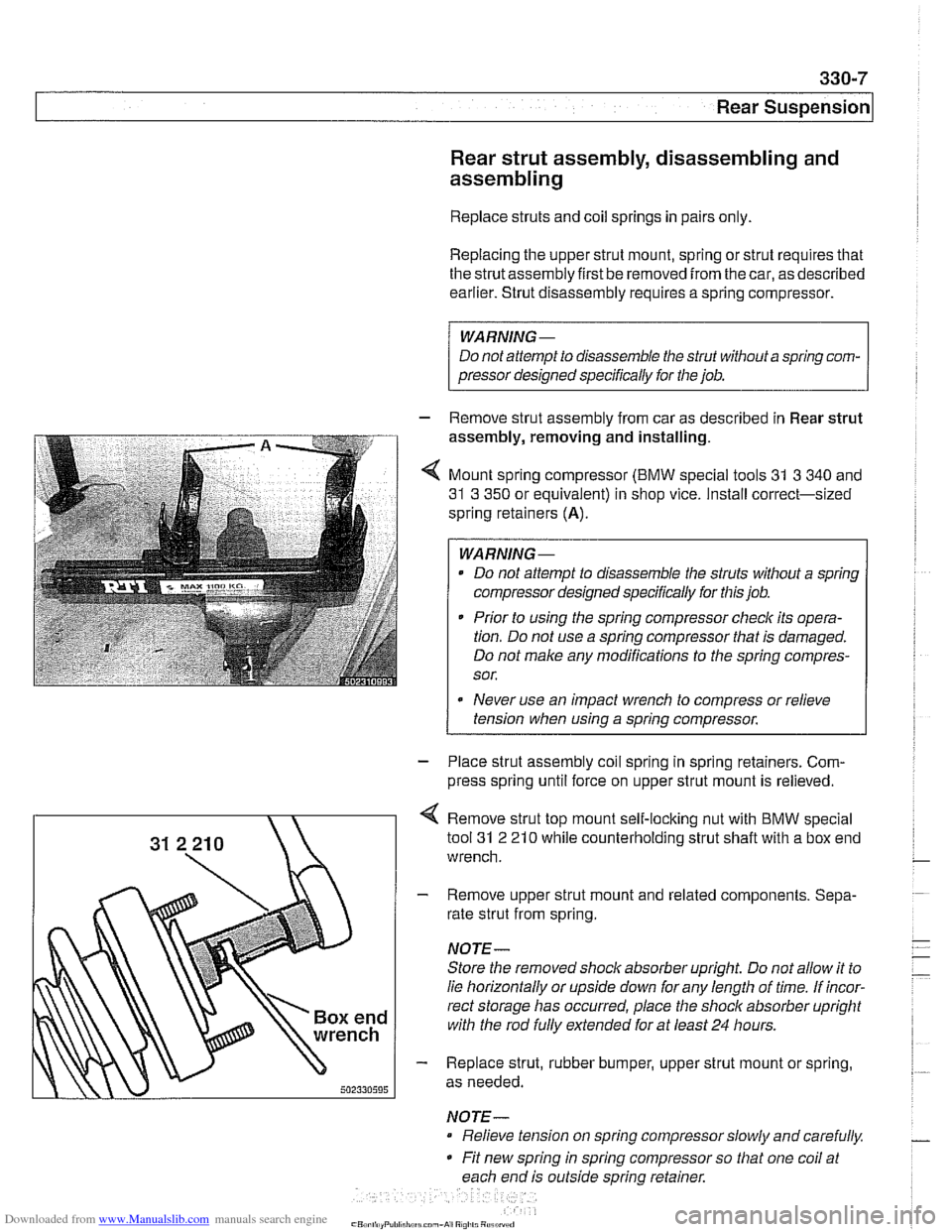
4 Mount spring compressor (BMW special tools 31 3 340 and
31 3 350 or equivalent) in shop vice. Install correct-sized
spring retainers
(A).
WARNING-
Do not attempt to disassemble the struts without a spring
compressor designed specifically for this job.
* Prior to using the spring compressor checlc its opera-
tion. Do not use a spring compressor that is damaged.
Do not make any modifications to the spring compres-
sor.
Never use an impact wrench to compress or relieve
tension when using a spring compressor.
1
- Place strut assembly coil spring in spring retainers. Com-
press spring until force on upper strut mount is relieved.
Remove strut top mount self-locking nut with BMW special
tool
31 2 21 0 while counterholding strut shaft with a box end
wrench.
- Remove upper strut mount and related components. Sepa-
rate strut from spring.
NOTE-
Store the removed shock absorber upright Do not allow it to
lie horizontally or upside down for any length of time. If incor-
rect storage has occurred, place the
shoclc absorber upright
with the rod
fully extended for at least 24 hours.
- Replace strut, rubber bumper, upper strut mount or spring,
as needed.
NOTE- Relieve tension on spring compressor slowly and carefully.
Fit new spring in spring compressor so that one coil at
each end is outside spring retainer.
Page 704 of 1002
Downloaded from www.Manualslib.com manuals search engine
330-8
Rear Suspension
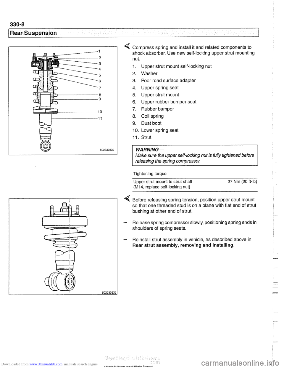
4 Compress spring and install it and related components to
shock absorber. Use new self-locking upper strut mounting
nut.
1. Upper strut mount self-locking nut
2. Washer
3. Poor road surface adapter
4. Upper spring seat
5. Upper strut mount
6. Upper rubber bumper seat
7. Rubber bumper
8. Coil spring
9. Dust boot
10. Lower spring seat
I I. Strut
WARNING-
Male sure the upperself-locking nut is fully tightened before
releasing the spring compressor.
Tightening torque
Upper strut mount to strut shaft
27 Nm (20 ft-lb)
(M14, replace self-locking nut)
4 Before releasing spring tension, position upper strut mount
so that one threaded stud is on a plane with flat end of strut
bushing at other end of strut.
- Release spring compressorslowly, positioning spring ends in
shoulders of spring seats.
- Reinstall strut assembly in vehicle, as described above in
Rear strut assembly, removing and installing.
Page 741 of 1002
Downloaded from www.Manualslib.com manuals search engine
-- I
I: ... . -. Rear Suspension! -- .- -
Air compressor pump relay, removing and
installing
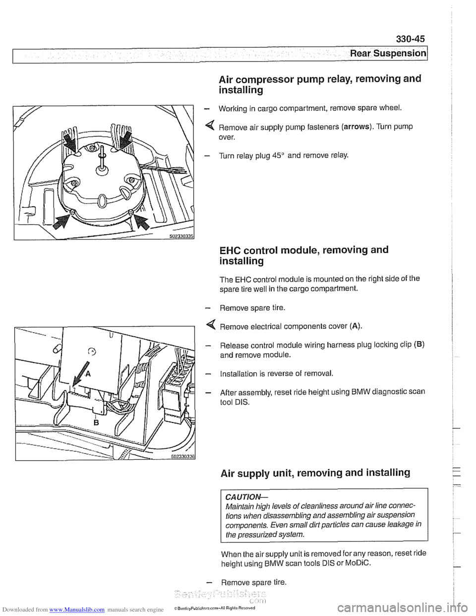
- Working in cargo compartment, remove spare wheel.
4 Remove air supply pump fasteners (arrows). Turn pump
over.
- Turn relay plug 45" and remove relay.
EHC control module, removing and
installing
The EHC control module is mounted on the right side of the
spare tire
well in the cargo compartment.
- Remove spare tire.
4 Remove electrical components cover (A).
- Release control module wiring harness plug loclting clip (B)
and remove module.
- Installation is reverse of removal.
- After assembly, reset ride height using BMW diagnostic scan
tool DIS.
Air supply unit, removing and installing
CAUTION-
Maintain high levels of cleanliness around air line connec-
tions when disassembling and assembling air suspension
components. Even small dirt particles can cause
leakage in
the pressurized system.
When the airsupply unit is removed for any reason, reset ride
height using BMW scan tools DIS or
MoDiC.
- Remove spare tire.
i~B,!n,,ayPubi.l,c~u.c~"~-A~~ R