electrical BMW 528i 2000 E39 Workshop Manual
[x] Cancel search | Manufacturer: BMW, Model Year: 2000, Model line: 528i, Model: BMW 528i 2000 E39Pages: 1002
Page 942 of 1002
Downloaded from www.Manualslib.com manuals search engine
- -
Seat Belts
Front seat belt tensioner, removing and
installing
- Disconnect battery negative (-) cable in trunk.
The
front seat belt loclts are equipped with pyrotechnic (ex-
plosive charge) automatic tensioners. These tensioners are
designed to automatically retract and tension the seat belt by
55 mm (approximately 2 inches) in the event of an accident.
CAUTION-
Prior to disconnecting the battery, read the battery discon-
nection cautions given in
001 General Warnings and Cau-
tions.
WARNING-
Pyrotechnic seat belt tensioners are powerful devices and
should be handled with extreme care. Incorrect handling
can trigger the tensioner and cause injury
BMW recommends that all repair or replacement work
on pyrotechnic devices must be carried out by a quali-
fied BMW technician.
Be sure to disconnect the battery and wait
5 seconds
before attempting to work on pyrotechnic devices.
Pyrotechnic devices cannot be repaired. Always re-
place them.
Never treat pyrotechnic components with cleaning
agents or grease.
- Do not expose pyrotechnic components to tempera-
tures above
75% (167°F).
Pyrotechnic components can only be tested electrically
when installedusing the
BMWService Tester (DISplus,
GTI, or MoDiC).
Do not fire a pyrotechnic gas generatorprior to dispos-
al. It must be fired by a special disposal company or
shipped
back to BMW in the packaging of the new com-
ponent.
During body straightening and welding with an electric
arc welder, always disconnect the battery and the con-
nection to the pyrotechnic gas generators.
- Remove front seat as described in 520 Seats.
-
Page 955 of 1002
Downloaded from www.Manualslib.com manuals search engine
Airbag System (SRS)~
MRS control module, replacing
- Disconnect negative (-) cable from battery and cover nega-
tive terminal with insulating material.
CAUTIOI\C
Prior to disconnecting the battery, read the battery discon-
nection cautionsgiven in001 General Warnings and
Cau-
tions.
- Remove center console between front seats. See 513 lnteri-
or Trim.
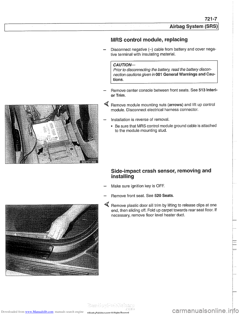
Remove module mounting nuts (arrows) and lift up control
module. Disconnect electrical harness connector.
Installation is reverse of removal.
Be sure that MRS control module ground cable is attached
to the module mounting stud.
Side-impact crash sensor, removing and
installing
- Make sure ignition key is OFF.
- Remove front seat. See 520 Seats.
Remove plastic door sill trim by lifting to release clips at one
end, then sliding off. Fold up carpet towards rear seat floor. If
necessary, remove floor level heater duct.
Page 956 of 1002
Downloaded from www.Manualslib.com manuals search engine
721 -8
(Airbag System (SRS)
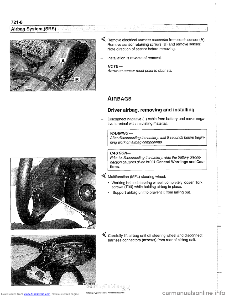
4 Remove electrical harness connector from crash sensor (A).
Remove sensor retaining screws (6) and remove sensor.
Note direction of sensor before removing.
- Installation is reverse of removal,
NOTE -
Arrow on sensor must point to door sill.
Driver airbag, removing and installing
- Disconnect negative (-) cable from battery and cover nega-
tive terminal with insulating material.
WARNING-
After disconnecting the batter)! wait 5 seconds before begin-
ning work on
airbag components.
CAUTION-
Prior to disconnecting the batter)! read the battery discon-
nection cautionsgiven
in001 General Warnings and Cau-
tions.
4 Multifunction (MFL) steering wheel:
. Working behind steering wheel, completely loosen Torx
screws
(T30) while holding airbag in place.
Support
airbag unit to prevent it from falling out.
Page 957 of 1002
Downloaded from www.Manualslib.com manuals search engine
721 -9
Airbaq System ~SRS)~
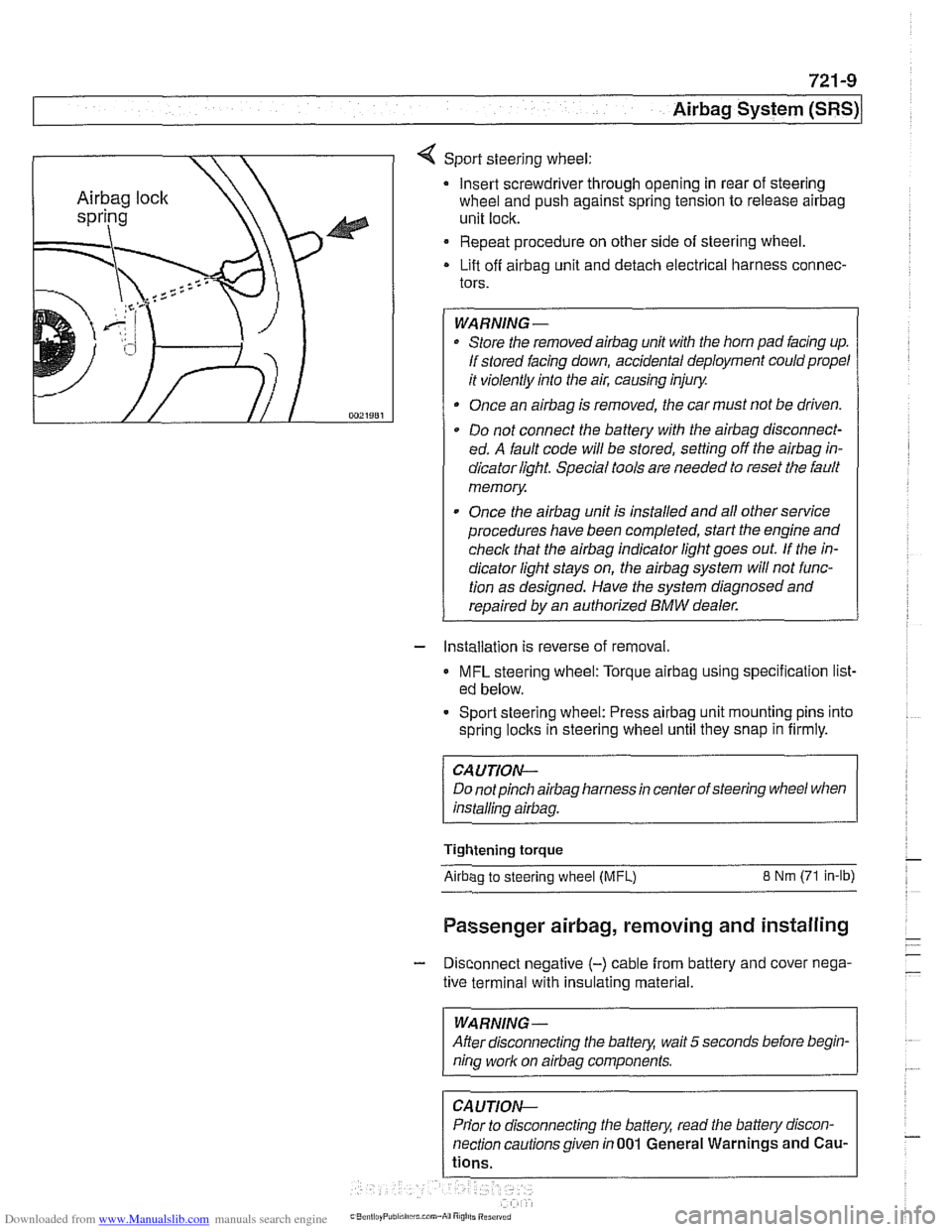
4 Sport steering wheel:
Insert screwdriver through opening in rear of steering
wheel and push against spring tension to release
airbag
unit lock.
Repeat procedure on other side of steering wheel.
Lift off
airbag unit and detach electrical harness connec-
tors.
WARNING-
Store the removedairbag unit with the horn pad facing up.
If stored facing down, accidental deployment could propel
it violently into the air, causing injury.
Once an
airbag is removed, the car must not be driven.
Do not connect the battery with the
airbag disconnect-
ed. A fault code will be stored, setting off the
airbag in-
dicator light Special tools are needed to reset the fault
memory
Once the
airbag unit is installed and all other service
procedures have been completed, start the engine and
check that the
airbag indicator light goes out. If the in-
dicator light stays on, the
airbag system will not func-
tion as designed. Have the system diagnosed and
repaired by an authorized
BMW dealer.
- Installation is reverse of removal.
MFL steering wheel: Torque airbag using specification list-
ed below.
- Sport steering wheel: Press airbag unit mounting pins into
spring
loclts in steering wheel until they snap in firmly.
CAUTION--
Do notpinch airbag harness in center of steering wheel when
installino
airbaa.
Tightening torque
Airbao to steerino wheel IMFL) 8 Nm (71 in-lb)
Passenger airbag, removing and installing
- Disconnect negative (-) cable from battery and cover nega-
tive terminal with insulating material.
--
WARNING -
After disconnecting the batteg wait 5 seconds before begin-
nina work on airbaa components.
Prior to disconnecting the battery, read the battery discon-
nection cautionsgiven in001 General Warnings and
Cau-
Page 958 of 1002
Downloaded from www.Manualslib.com manuals search engine
721 -1 0
/Airbag System (SRS)
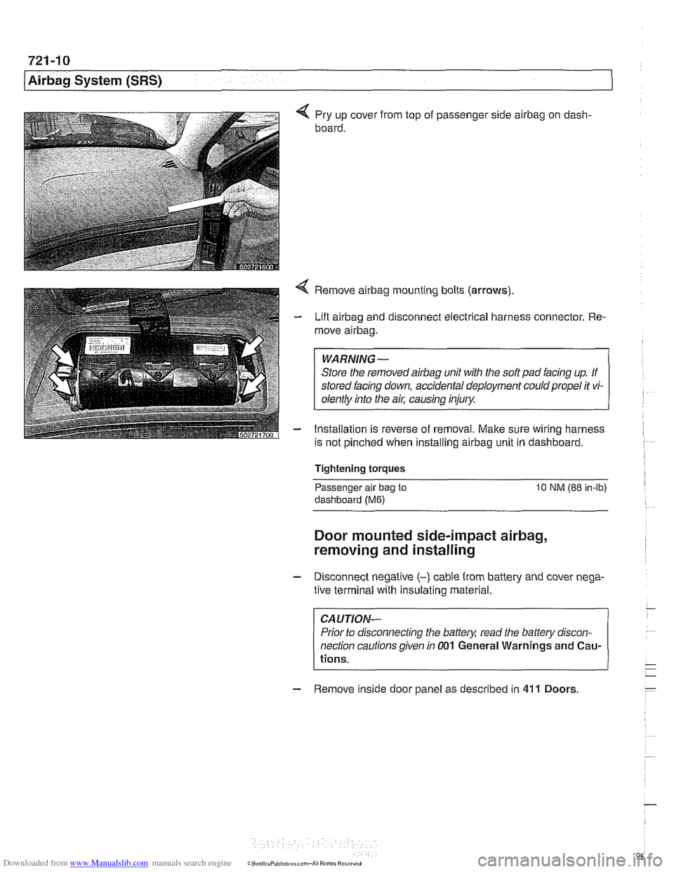
4 Pry up cover from top of passenger side airbag on dash-
board.
4 Remove airbag mounting bolts (arrows)
- Lift airbag and disconnect electrical harness connector. Re-
move
airbag.
WARNING-
Store the removed airbag unit with the soft pad facing up. If
stored facing down, accidental deployment could propel it vi-
olentlv into the
ail: causino inium
- Installation is reverse of removal. Make sure wiring harness
is not pinched when installing
airbag unit in dashboard.
Tightening torques
-
Passenger alr bag to 10 NM (88 in-lb)
dashboard (Me)
Door mounted side-impact airbag,
removing and installing
- Disconnect negatlve (-) cable from battery and cover nega-
tive terminal with insulating material.
CAUTION-
Prior to disconnecting the battea read the battery discon-
nection cautions given
in 001 General Warnings and Cau-
tions.
- Remove inside door panel as described in 41 1 Doors
Page 959 of 1002
Downloaded from www.Manualslib.com manuals search engine
721 -1 1
Airbag System (SRS)~
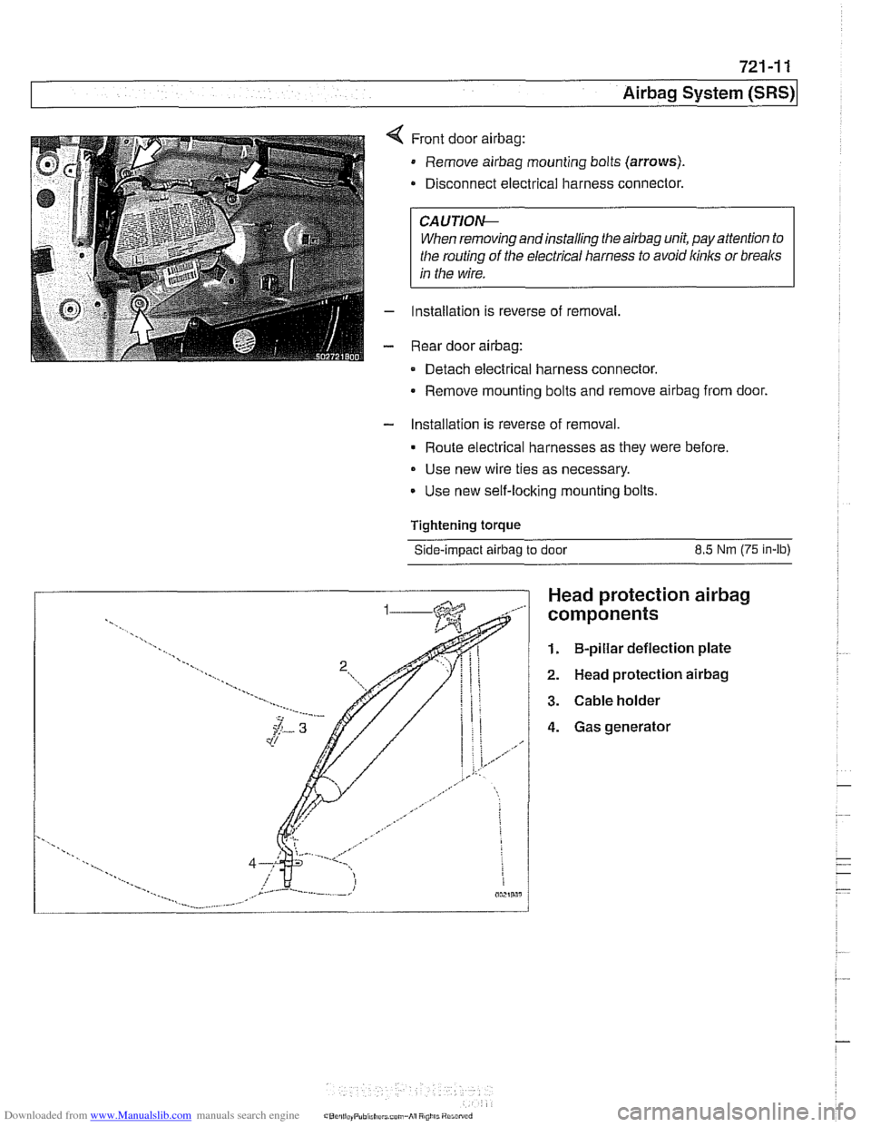
Front door airbag:
Remove airbag mounting bolts (arrows).
Disconnect electrical harness connector.
CAUTIOI\C
When removing andinstalling the airbag unit, pay attention to
the routing
of the electrical harness to avoid kinks or breaks
in the wire.
Installation is reverse of removal,
Rear door
airbag:
Detach electrical harness connector.
Remove mounting bolts and remove
airbag from door.
- Installation is reverse of removal.
Route electrical harnesses as they were before.
Use new wire ties as necessary.
Use new self-locking mounting bolts.
Tightening
torque
Side-impact airbag to door 8.5 Nm (75 in-lb)
Head protection airbag
components
1. B-pillar deflection plate
2. Head protection airbag
3. Cable holder
4. Gas generator
Page 970 of 1002
Downloaded from www.Manualslib.com manuals search engine
On-Board Diagnostics
l~utornatic transmission diagnostic trouble codes (continued) -
P-code /BMW-FC I DTC Definition - PO732
PO732
PO733
PO733
PO733
PO733
PO734 -
I I
I I
PO742 / 48 l~orque Converter Clutch Circuit Stuck On
PO734
100
132
53
57 122
133
54
PO735
PO735
PO735
PO740
PO740
PO740
PO741
I I
PO743 14 l~or~ue Converter Clutch Circuit Electrical
Gear
2 Incorrect Ratio
Gear 2 Incorrect Ratio
Gear 3 incorrect Ratio
Gear 3 Incorrect Ratio
Gear 3 Incorrect Ratio
Gear 3 Incorrect Ratio
Gear 4 Incorrect Ratio
Gear
4 Incorrect Rat10 PO734
I I
PO743 132 l~or~ue Converter Clutch Circuit Electrical
PO734 1134 IGear 4 Incorrect Ratio
123
55 101
135
4
48 111
48 Gear 5 Incorrect Ratio
Gear 5
Incorrect Ratio
Gear 5 Incorrect Ratio
Torque Converter Clutch
Circuitlopen
Torque Converter Clutch Circuitlopen
Torque Converter Clutch Circuitlopen
Torque Converter Clutch Circuit Performance or Stuclc Off
PO745
PO748
PO748
PO750
PO751
PO751
I I
PO755 117 IShift Solenoid '8' I
PO752
PO753
PO753
PO756 117 I~hift Solenoid '8' Performance or Stuck Off I
1
1
5
16
6 16 Pressure Control Solenoid 'A'
Pressure Control Solenoid 'A' Electrical
Pressure Control Solenoid
'A' Electrical
Shift Solenoid
'A'
Shift Solenoid 'A' Performance or Stuck Off
Shift Solenoid
'A' Performance or Stuck Off
16
16
30 Shift
Solenoid
'A' Stuck On
Shift Solenoid 'A' Electrical
Shift Solenoid
'A' Electrical
PO757
PO758
PO758
PO760
PO761
17
17
33 18
18 Shift
Solenoid '8' Stuclc On
Shift Solenoid
'8' Electrical
Shift Solenoid
'8' Electrical
Shift Solenoid
'C'
Shift Solenoid 'C' Performance or Stuclc Off
Page 971 of 1002
Downloaded from www.Manualslib.com manuals search engine
OBD-11
On-Board Diagnostics
Automatic transmission diagnostic trouble codes (continued)
P-code
PO762
PO763
PO763
PO763
PO775
PO782
PO783 I I
PO795
PO798
PO962
PO963
PO966
PO967
PO970
PO971
BMW-FC
18
2 18
32
2
57
58
I I -
DTC Definition
Shift Solenoid 'C' Stuck On
Shift Solenoid
'C' Electrical
Shift Solenoid
'C' Electrical
Shift Solenoid
'C' Electrical
Pressure Control Solenoid
'B'
2-3 Shift
3-4 Shift
PO778 12 I Pressure Control Solenoid 'B' Electrical
3
3
1
1
2
2
3
3
PO973
PO979
PI 700
PI719
PI720
Pi731
PI732
PI734
Pressure Control Solenoid 'C'
Pressure Control Solenoid
'C' Electrical
Pressure Control Solenoid
'A' Control Circuit Low
Pressure Control Solenoid 'A' Control Circuit High
Pressure Control Solenoid
'6' Control Circuit Low
Pressure Control Solenoid
'0' Control Circuit High
Pressure Control Solenoid 'C' Control Circuit Low
Pressure Control Solenoid 'C' Control Circuit
High
PI734
PI738
Pi738
PO976 117 IShift Solenoid 'B' Control Circuit Low
16
18
62 144
129
51
65
1
PI743
PI743
PI743
PI746
PI746 - Pi747
Shift Solenoid 'A' Control Circuit Low
Shift Solenoid 'C' Control Circuit Low
Double Error Output Speed and
inputflurbine Speed
CAN Version Error
CAN
Timeout Control Module
Gear
1 manual Incorrect Ratio
Gear Monitoring 4 at Electrical Substitute Program
Pressure
Control Solenoid 'B' Eieclrical
2
3
29
PI747
PI747
Pressure Control Solenoid 'B' Electrical
Pressure Control Solenoid
'C' Electrical
Pressure Control Solenoid
'C' Electrical
4
5
51
83 104 Pressure Control Solenoid
'E' Electrical (M44lM52: Brake
Band Electrical)
Pressure Control Solenoid
'E' Electrical (M44lM52: Bralte Band Electrical)
Pressure Control Solenoid
'E' Electrical (M44lM52: Brake Band Electrical)
Transmission Control Module Output Stage
Transmission Control Module Output Stage
129 128 CAN-Bus Monitoring CAN-Bus Monitoring
144 CAN-Bus Monitoring
Page 973 of 1002
Downloaded from www.Manualslib.com manuals search engine
On-Board Diagnostics
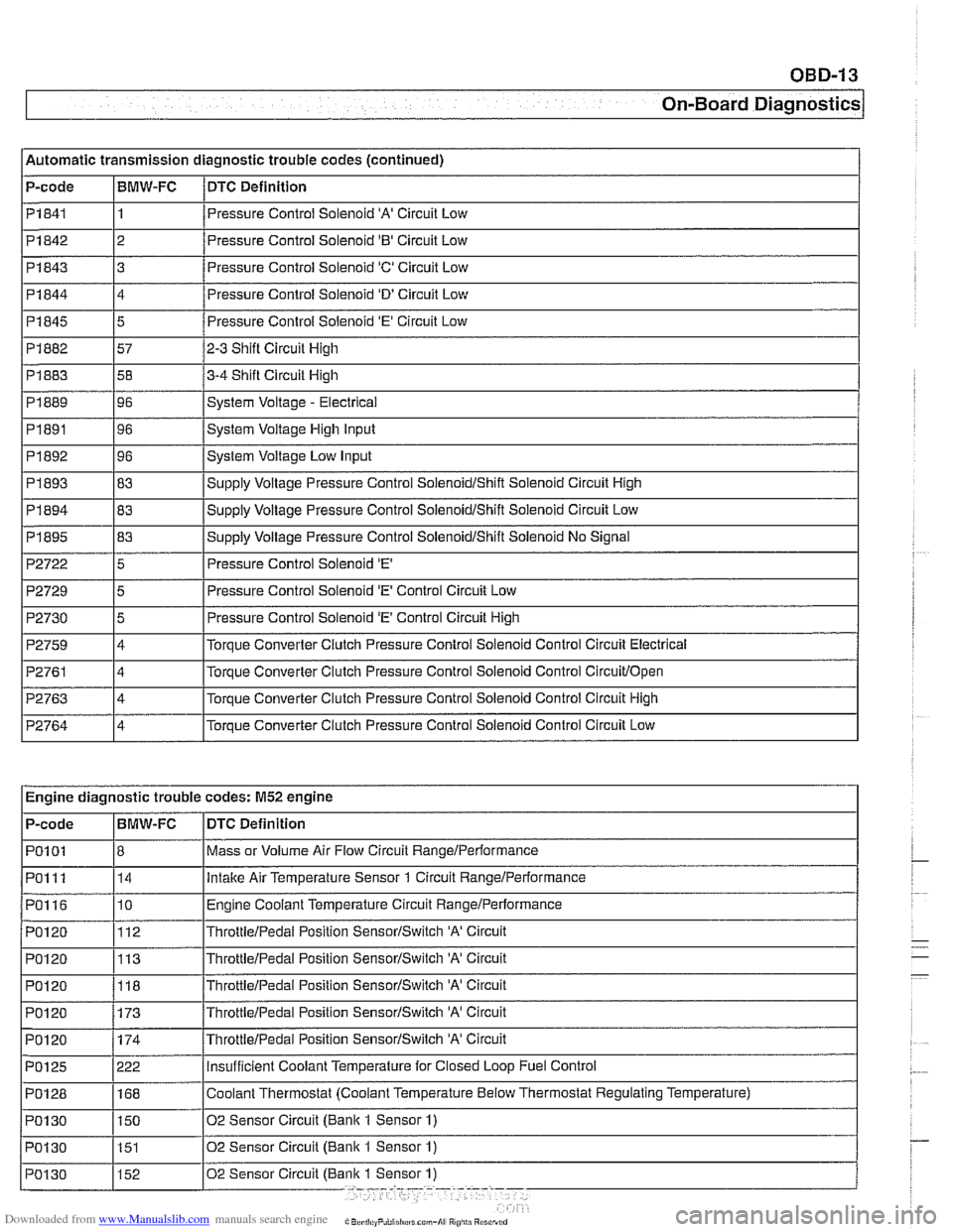
l~utomatic transmission diagnostic trouble codes (continued)
P-code
1 Pi844
I I
14 /Pressure Control Solenoid 'D' Circuit Low
I I PI841 11 /Pressure Control Solenoid 'A' Circuit Low
BMW-FC
Pi842
I
P2722 15 I Pressure Control Solenoid 'E' I
DTC
Definition
Pi 845
Pi 882
Pi 883
PI 889
PI891
PI 892
PI 893
Pi 843 3 8
2 Pressure Control Solenoid '0' Circuit Low
5
57
58
96
96
96
83
P2729
P2730
P2759
P2761
P2763
P2764
Pressure Control Solenoid 'E' Circuit Low
2-3 Shift Circuit High
3-4 Shift Circuit High
System Voltage
- Electrical
System Voltage High Input
System Voltage Low Input
SUDP~V Voltaqe Pressure Control SoienoidIShift Solenoid Circuit High
~~ ~~ ~ Engine diagnostic trouble codes: M52 engine
5
5
4
4
4
4
I I
Pressure Control Solenoid 'E' Control Circuit Low
Pressure Control Solenoid
'E' Control Circuit High
Torque Converter Clutch Pressure Control
Solenoid Control Circuit Electrical
Torque Converter Clutch Pressure Control Solenoid Control
Circuitlopen
Torque Converter Clutch Pressure Control Solenoid Control Circuit High
Torque Converter Clutch Pressure Control Solenoid Control Circuit Low
DTC Definition
Mass or Volume Air
Flow Circuit RangeIPerformance
lntalte Air Temperature Sensor 1 Circuit Rangelperformance
Engine Coolant Temperature Circuit RangeIPerformance
ThrottieIPedai Position SensorISwitch 'A' Circuit
ThrottleIPedai Position SensorISwitch 'A' Circuit
P-code
PO1
01
PO1 11
PO116
PO120
PO120
PO1 20 BMW-FC
8 14
10
112
113
POI 20 1173 /~hrottie/~edal Position SensorISwitch 'A' Circuit
118
ThrottieIPedai Position SensorISwitch 'A' Circuit
Page 975 of 1002
Downloaded from www.Manualslib.com manuals search engine
OBD-15
On-Board ~iagnosticsl
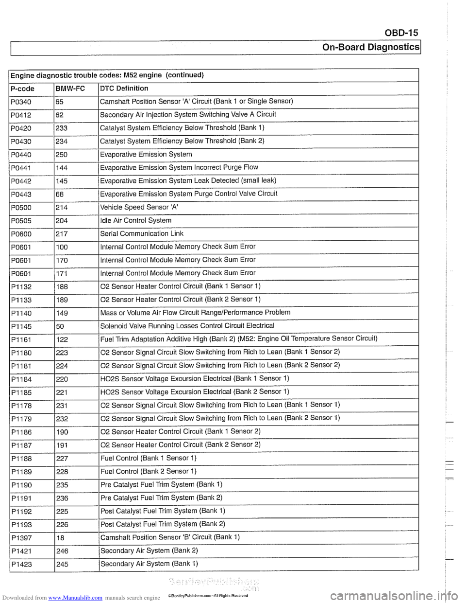
Engine diagnostic trouble codes: M52 engine (continued)
P-code
PO340
PO412
PO420
PO430
PO440
PO441
PO442
PO443
PO500
PO505
PO600
PO601
PO601
I PO601
~1132
~1133
BMW-FC
65
62
233
234
250 144
-
145
68
214
i I
DTC Definition
Camshalt Position Sensor 'A' Circuit (Bank 1 or Single Sensor)
Secondary Air Injection System Switching Valve A Circuit
Catalyst System Efficiency Below Threshold
(Bank 1)
Catalyst System Efficiency Below Threshold (Bank 2)
Evaporative Emission System
Eva~orative Emission Svstem Incorrect Purge Flow .
Evaporative Emission System Leak Detected (small leak)
Evaporative Emission System Purge Control Valve Circuit
Vehicle Speed Sensor 'A'
204
21 7
100
170
171
188
189
PI161
PI180
PI181
PI184
PI185
PI178
02 Sensor Heater Control Circuit (Bank 2 Sensor 2) I
idle Air Control System
Serial Communication
Link
Internal Control Module Memory Check Sum Error
Internal Control Module Memory
Check Sum Error
Internal Control Module Memory
Check Sum Error
02 Sensor Heater Control Circuit (Bank 1 Sensor
1)
02 Sensor Heater Control Circuit (Bank 2 Sensor 1)
Mass or Volume Air Flow Circuit RangeIPerlormance Problem PI140
I
I I
P1188 1227 I Fuel Control (Bank 1 Sensor 1)
PI145 150 /Solenoid Valve Running Losses Control Circuit Electrical
149
122
223
224
220 221
231
I I
P1189 1228 I Fuel Control (Banlc 2 Sensor 1)
Fuel Trim Adaptation Additive High (Bank 2) (M52: Engine Oil Temperature Sensor Circuit)
02 Sensor Signal Circuit Slow Switching from Rich to Lean
(Bank 1 Sensor 2)
02 Sensor Signal Circuit Slow Switching from Rich to Lean
(Bank 2 Sensor 2)
H02S Sensor Voltage Excursion Electrical (Banlc 1 Sensor 1)
HO2S Sensor Voltage Excursion Electrical (Banlc 2 Sensor 1)
02 Sensor Sianai Circuit Slow Switchina from Rich to Lean (Bank 1 Sensor 1)
02 Sensor Signal Circuit Slow Switching from Rich to Lean (Bank 2 Sensor 1) PI179
I I
PI190 1235 I Pre Catalyst Fuel Trim System (Banlc 1)
PI186 1190 102 Sensor Heater Control Circuit (Banlc 1 Sensor 2)
232
I I
PI191 1236 I Pre
Catalyst Fuel Trim System (Banlc 2)
PI192
. . -- - i Pi193 1226 I Post Catalvst Fuel Trim Svstem (Bank 2)
225
PI397
I I
Post Catalyst Fuel Trim System (Bank 1)
PI421 1246 /Secondarv Air System (Bank 2)
18
Secondary Air System (Bank
1) PI423
Camshaft Position Sensor '0' Circuit (Bank 1)
I 245