Cam sensor BMW 528i 2000 E39 Owner's Manual
[x] Cancel search | Manufacturer: BMW, Model Year: 2000, Model line: 528i, Model: BMW 528i 2000 E39Pages: 1002
Page 274 of 1002
Downloaded from www.Manualslib.com manuals search engine
11 7-38
[Camshaft Timing Chain
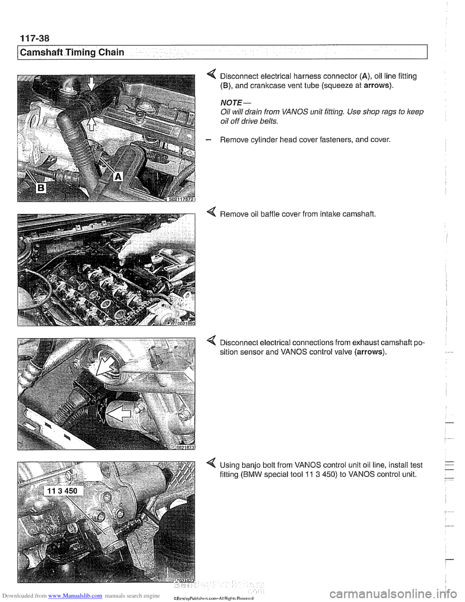
4 Disconnect electrical harness connector (A), oil line fitting
(B), and cranltcase vent tube (squeeze at arrows).
NOJE-
Oil will drain from VANOS unit fitting. Use shop rags to keep
oil off drive belts.
- Remove cylinder head cover fasteners, and cover.
4 Remove oil baffle cover from intake camshaft
4 D~sconnect electrical connections from exhaust camshaft po-
sition sensor and VANOS control valve (arrows).
4 Using banjo bolt from VANOS control unit oil line, install test
fitting
(BMW special tool 11 3 450) to VANOS control unit.
Page 279 of 1002
Downloaded from www.Manualslib.com manuals search engine
Camshaft Timing Chain
- Connect electrical harness connectors to camshaft position
sensors and VANOS solenoid valves.
- Remove BMW special locking tools from rear of cylinder
head.
- Remove cranltshaft locking tool and replace sealing plug.
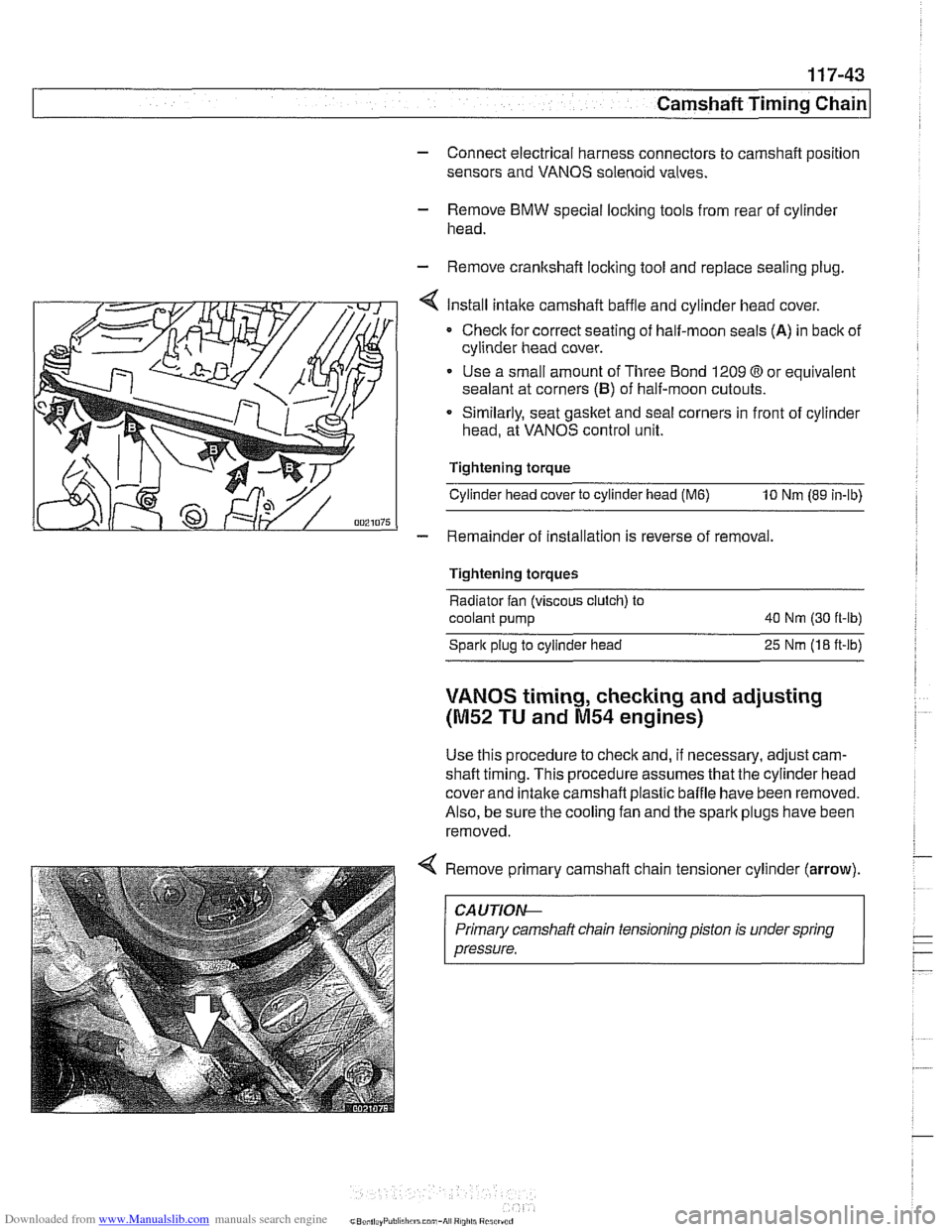
Install intake camshaft baffle and cylinder head cover.
Checlc for correct seating of half-moon seals (A) in back of
cylinder head cover.
Use a small amount of Three Bond 1209
O or equivalent
sealant at corners
(B) of half-moon cutouts.
Similarly, seat gasket and
seal corners in front of cylinder
head, at VANOS control unit.
Tightening torque
Cylinder head cover to cylinder head
(M6) 10 Nm (89 in-lb)
- Remainder of installation is reverse of removal.
Tightening torques
Radiator fan (viscous clutch) to
coolant pump 40
Nm (30 ft-lb)
Spark plug to cylinder head
25 Nrn (18 ft-lb)
VANOS timing, checking and adjusting
(M52 TU and M54 engines)
Use this procedure to check and, if necessary, adjust cam-
shaft timing. This procedure assumes that the cylinder head
cover and intake
camshaft plastic baffle have been removed.
Also, be sure the cooling fan and the spark plugs have been
removed.
Remove primary camshaft chain tensioner cylinder
(arrow).
~~ ~ ~~ ~--~
CA UTlOAC
Primary camshaft chain tensioning piston is under spring
pressure.
Page 303 of 1002
Downloaded from www.Manualslib.com manuals search engine
Camshaft Timing chain1
- Disconnect negative cable (-) from battery.
CAUTION-
Prior to disconnecting the battery, read the battery discon-
nection cautions given
in 001 General Cautions and
Warnings.
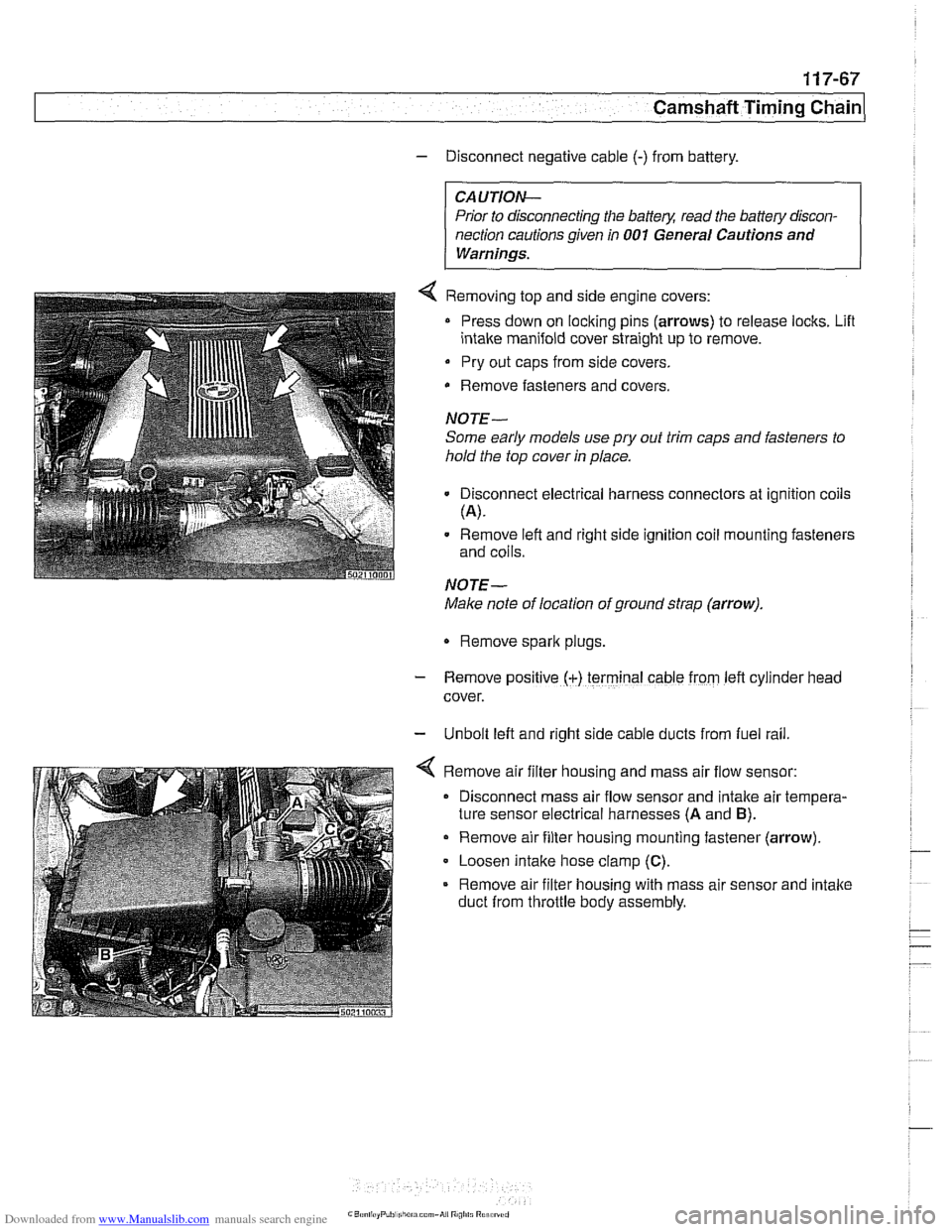
4 Removing top and side engine covers:
Press down on locking pins (arrows) to release locks. Lifl
intake manifold cover straight up to remove.
Pry out caps from side covers.
Remove fasteners
and covers.
NOTE-
Some early models use
pry out trim caps and fasteners to
hold the top cover in place.
Disconnect electrical harness connectors at ignition coils
(A).
Remove left and right side ignition coil mounting fasteners
and coils.
NOTE-
Make note of location of ground strap (arrow).
Remove spark plugs.
- Remove posltlve (+) terminal cable from left cylrnder head
cover.
- Unbolt left and right side cable ducts from fuel rail
Remove air filter housing and mass air flow sensor:
Disconnect mass air flow sensor and intake air tempera-
ture sensor electrical harnesses
(A and B).
Remove air filter housing mounting fastener (arrow)
Loosen intake hose clamp
(C).
Remove air filter housing with mass air sensor and intake
duct from throttle body assembly.
Page 306 of 1002
Downloaded from www.Manualslib.com manuals search engine
I Camshaft Timins Chain
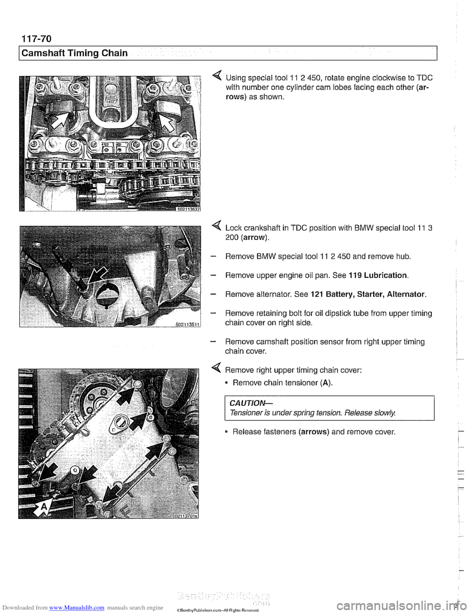
4 Using special tool 11 2 450, rotate engine clocltwise to TDC
with number one cylinder cam lobes facing each other (ar-
rows)
as shown.
4 Lock crankshaft in TDC position with BMW special tool 11 3
200 (arrow).
- Remove BMW special tool 11 2 450 and remove hub.
- Remove upper engine oil pan. See 119 Lubrication.
- Remove alternator. See 121 Battery, Starter, Alternator.
- Remove retaining bolt for oil dipstick tube from upper timing
chain cover on right side.
- Remove camshaft position sensor from right upper timing
chain cover.
< Remove right upper timing chain cover:
Remove chain tensioner
(A).
CAUTIOG
Tensioner is under spring tension. Release slowly. 1
Release fasteners (arrows) and remove cover
Page 307 of 1002
Downloaded from www.Manualslib.com manuals search engine
Camshaft Timing chain1
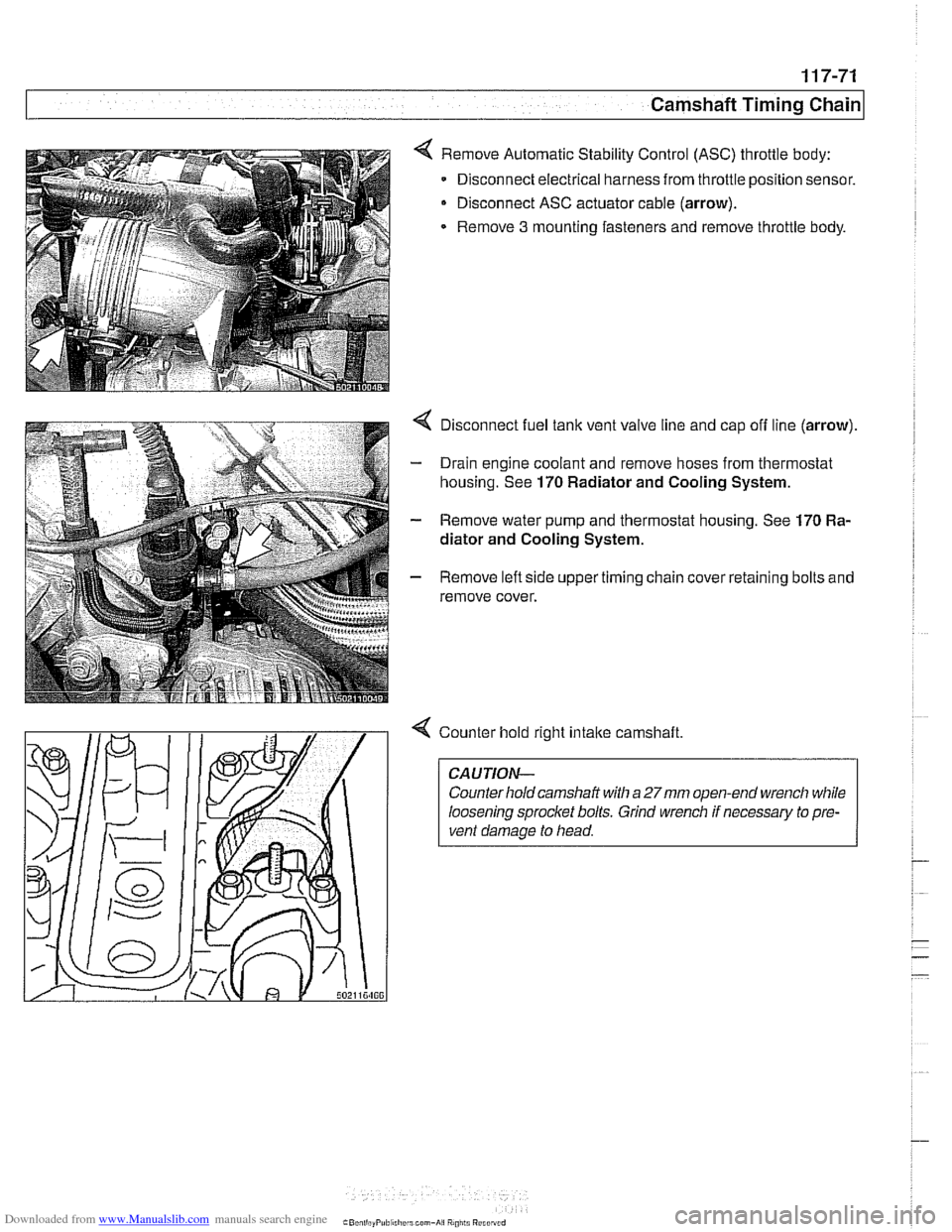
< Remove Automatic Stability Control (ASC) throttle body:
Disconnect electrical harness from throttle position sensor.
Disconnect ASC actuator cable (arrow).
Remove
3 mounting fasteners and remove throttle body.
4 Disconnect fuel tank vent valve line and cap off line (arrow).
- Drain engine coolant and remove hoses from thermostat
housing. See
170 Radiator and Cooling System.
- Remove water pump and thermostat housing. See 170 Ra-
diator and Cooling System.
- Remove left side upper timing chain cover retaining bolts and
remove cover.
4 Counter hold right intake camshaft
CAUTION-
Counter hold camshaft with a 27mm open-end wrench while
loosening sprocket bolts. Grind wrench if necessary to pre-
vent damage to head.
Page 311 of 1002
Downloaded from www.Manualslib.com manuals search engine
Camshaft Timing Chain1
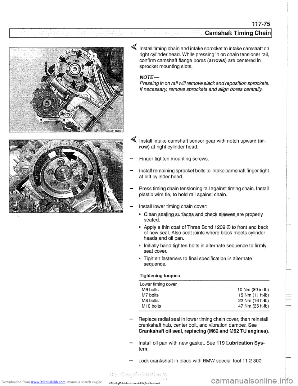
lnstall timing chain and intake sprocket to intake camshaft on
right cylinder head. While pressing in on chain tensioner rail,
confirm camshaft flange bores (arrows) are centered in
sprocket mounting slots.
NOTE-
Pressing in on rail will remove slack and reposition sprockets.
If
necessarx remove sproclets and align bores centrally.
lnstall intake camshaft sensor gear with notch upward (ar-
row) at right cylinder head.
- Finger tighten mounting screws.
- lnstall remaining sprocket bolts to intake camshaft finger tight
at left cylinder head.
- Press timing chain tensioning rail against timing chain. lnstall
plastic wire
tie, to hold rail against chain.
- lnstall lower timing chain cover:
Clean sealing surfaces and check sleeves are properly
seated.
Apply a thin coat of Three Bond 1209
8 to front and back
of new seal. Also coat joints where block meets cylinder
heads and oil pan.
Initially hand tighten bolts in alternate sequence to firmly
seat cover.
Tighten fasteners to final specification in alternate
sequence.
Tightening torques Lower timing cover
M6 bolts 10 Nrn (89 in-lb)
M7 bolts 15 Nm (1 1 ft-lb)
ME bolts 22 Nm (1 6 ft-lb)
M10 bolts 47 Nm (35 ft-lb)
- Replace radial seal in lower timing chain cover, then reinstall
crankshaft hub, center bolt, and vibration damper. See
Crankshaft oil seal, replacing
(M62 and M62 TU engines).
- lnstall oil pan with new gasket. See 119 Lubrication Sys-
tem.
- Lock crankshaft in place with BMW special tool 11 2 300
Page 315 of 1002
Downloaded from www.Manualslib.com manuals search engine
Camshaft Timing chain/
Camshaft timing, checking and adjusting
(M62 engine)
WARNING -
Allow engine to cool before beginning this procedure. 1
- Working inside luggage compartment, disconnect negative
battery cable.
CAUTIOI\C
Prior to disconnecting battery cable, read the battery discon-
nection cautions given
in 001 General Cautions and
Warninss.
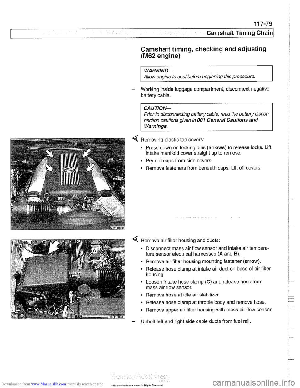
4 Removing plastic top covers:
Press down on locking pins (arrows) to release locks. Lift
intake manifold cover straight up to remove.
Pry out caps from side covers.
Remove fasteners from beneath
caDs. Lift off covers.
4 Remove air filter housing and ducts:
Disconnect mass air flow sensor and intake air tempera-
ture sensor electrical harnesses
(A and B).
Remove air filter housing mounting fastener (arrow).
Release hose clamp at intake air duct on base of air filter
housing.
Loosen intake hose clamp
(C) and release hose from
mass air flow sensor.
Remove hose at idle air stabilizer.
Release hose clamp at throttle body and remove hose.
Remove upper air filter housing with mass air flow sensor.
- Unbolt left and right side cable ducts from fuel rail.
Page 349 of 1002
Downloaded from www.Manualslib.com manuals search engine
120 lgnition System
...................... General
Special tools ...................
Warnings and cautions ...........
Engine management .............
................. lgnition system
Ignition system. troubleshooting
....
... Oscilloscope diagnostic diagrams
................ Misfire detection
............. Ignition System Service 120-9
.................... Ignition firing order 120-9
.............. Disabling ignition system 120-10
................... Checking for spark 120-1 0
lgnition coil assembly.
................. testing and replacing 120-1 0
.............. Crankshaftspeedsensor 120-12
............. Camshaft position sensors 120-1 4
...................... Knocksensors 120-16
Page 362 of 1002
Downloaded from www.Manualslib.com manuals search engine
I Ignition System
Camshaft position sensors
The camshaft position sensors are used by the englne man-
agement system for VANOS control, sequential fuel injection
and knock control.
Intake camshaft position sensor, replacing
(M52,M52 TU
and M54 engines)
- Make certain ignition has been turned off.
- Remove plastic cover from above fuel injectors by prying off
bolt covers and removing cover mounting bolts.
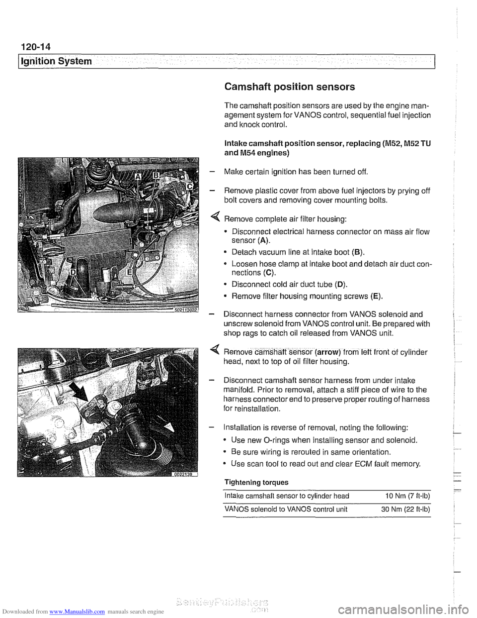
Remove complete air filter housing:
Disconnect electrical harness connector on mass air flow
sensor
(A).
Detach vacuum line at intake boot (B).
Loosen hose clamp at intake boot and detach air duct con-
nections
(C).
* Disconnect cold air duct tube (D).
Remove filter housing mounting screws (E).
- Disconnect harness connector from VANOS solenoid and
unscrew solenoid from VANOS control unit. Be prepared with
shop rags to catch oil released from VANOS unit.
Remove camshaft sensor (arrow) from
left front of cyl~nder
head, next to top of oil filter housing.
Disconnect camshaft sensor harness from under intake
manifold. Prior to removal, attach a stiff piece of wire to the
harness connector end to preserve proper routing of harness
for reinstallation.
Installation is reverse of removal, noting the following:
Use new O-rings when installing sensor and solenoid.
Be sure wiring is rerouted in same orientation.
Use scan tool to read out and clear
ECM fault memory
Tightening torques
-
Intake camshaft sensor to cylinder head 10 Nrn (7 ft-lb)
VANOS solenoid to VANOS control unit 30 Nm (22 ft-lb)
Page 363 of 1002
Downloaded from www.Manualslib.com manuals search engine
120-15
Ignition system1
Exhaust camshaft position sensor, replacing
(M52 TU and M54 engines)
- Make sure ignition has been turned off.
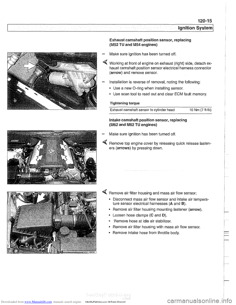
4 Working at front of engine on exhaust (right) side, detach ex-
haust camshaft position sensor electrical harness connector
(arrow) and remove sensor.
- Installation is reverse of removal, noting the following:
Use a new O-ring when installing sensor.
- Use scan tool to read out and clear ECM fault memory.
Tightening torque
Exhaust camshaft sensor
to cylinder head 10 Nm (7 ft-lb)
Intake camshaft position sensor, replacing
(M62 and M62 TU engines)
- Make sure ignition has been turned off
4 Remove top engine cover by releasing quick release fasten-
ers (arrows) by pressing down.
4 Remove air filter housing and mass air flow sensor:
Disconnect mass air flow sensor and
intalte air tempera-
ture sensor electrical harnesses
(A and B).
Remove air filter housing mounting fastener (arrow).
Loosen hose clamps
(C and D).
Remove hose at idle air stabilizer.
Remove air filter housing with mass air flow sensor.
- Remove intalte hose from throttle body.