Doors BMW 528i 2000 E39 Owner's Manual
[x] Cancel search | Manufacturer: BMW, Model Year: 2000, Model line: 528i, Model: BMW 528i 2000 E39Pages: 1002
Page 872 of 1002
Downloaded from www.Manualslib.com manuals search engine
51 2-8
Door Windows
Door window, adjusting
Whenever the door window or window regulator is removed,
window adjustment should be checked. The glass should
contact the top of the window squarely and should seat
against the window seal uniformly.
NOTE-
If the window does not contact the window seal uniformly,
wind noise or water infiltration may result.
- Remove door panel as described in 411 Doors.
- Disconnect negative (-) cable from battery. Remove airbag
unit and vapor barrier from door. See 721 Airbag System
(SRS).
WARNING-
Prior to disconnecting the batteg read the battery discon-
nection cautions given in
001 General Warnings and
Cautions.
Longitudinal adjustment
- Adjustments are made with window in open position.
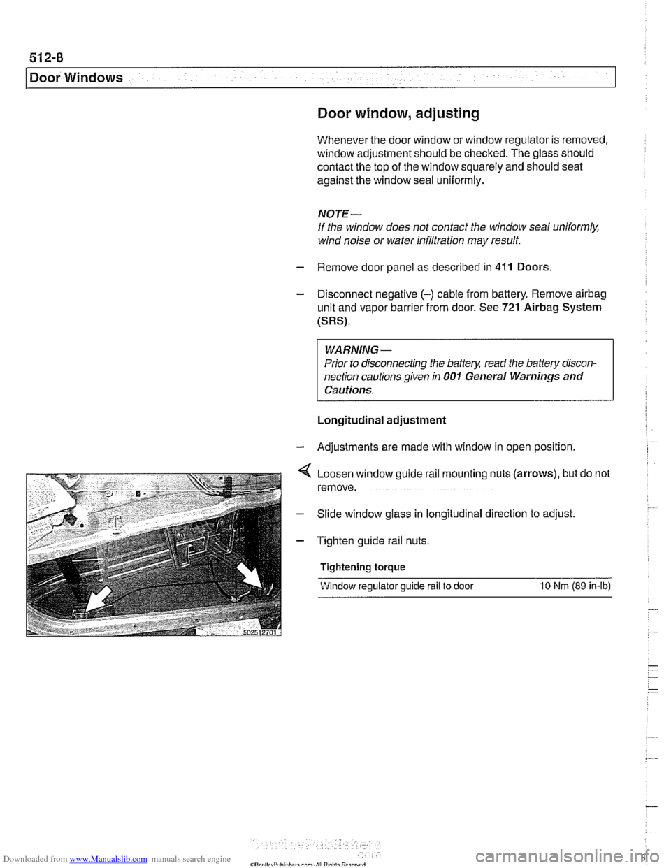
Loosen window guide rail mounting nuts (arrows), but do not
remove.
Slide window glass in longitudinal direction to adjust
Tighten guide rail nuts.
Tightening torque
Window regulator guide rail to door
10 Nrn (89 in-ib)
Page 873 of 1002
Downloaded from www.Manualslib.com manuals search engine
512-9
Door Windows
Vertical adjustment
- Adjustments are made with window in open position
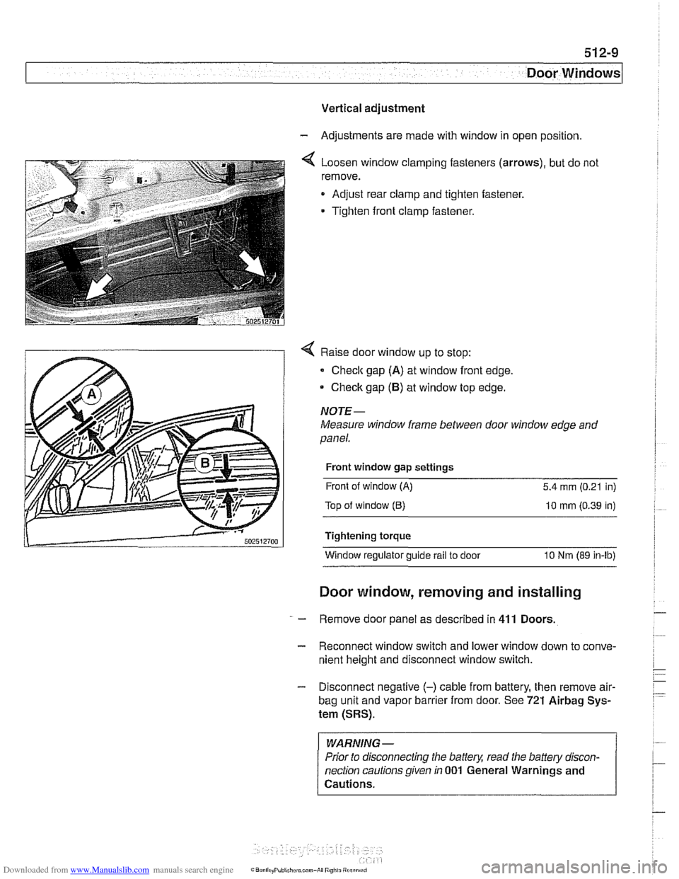
4 Loosen window clamping fasteners (arrows), but do not
remove.
Adjust rear clamp and tighten fastener.
Tighten front clamp fastener.
4 Raise door window up to stop:
Check gap (A) at window front edge,
Checlc gap (5) at window top edge.
NOJE-
Measure window frame between door window edge and
panel.
Front window gap settings
Front of window
(A) 5.4 mm (0.21 in)
Top of window
(6) 10 mm (0.39 in)
Tightening torque Window regulator guide
rail to door 10 Nm (89 in-lb)
Door window, removing and installing
- Remove door panel as described in 411 Doors
- Reconnect window switch and lower window down to conve-
nient height and disconnect window switch.
- Disconnect negative (-) cable from battery, then remove air-
bag unit and vapor barrier from door. See 721 Airbag Sys-
tem (SRS).
WARNING -
Prior to disconnecting the battery, read the battery discon-
nection cautions given
in 001 General Warnings and
Cautions.
Page 875 of 1002
Downloaded from www.Manualslib.com manuals search engine
Door Windows
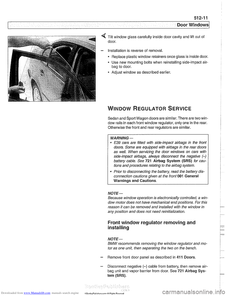
Tilt window glass carefully inside door cavity and lift out of
door.
Installation is reverse of removal.
Replace plastic window retainers once glass is inside door.
Use new mounting bolts when reinstalling side-impact
air-
bag to door.
Adjust window as described earlier,
Sedan and Sport Wagon doors are similar. There are two win-
dow rails in each front window regulator, only one in the rear.
Otherwise the front and rear regulators are similar.
WARNING-
E39 cars are Wed with side-impact airbags in the front
doors. Some are equipped with
airbags in the rear doors
as well. When servicing the door windows on cars with
side-impact airbags, always disconnect the negative
(-)
battery cable. See 721 Airbag System (SRS) for cau-
tions and procedures relating to the
airbag system.
Prior to disconnecting the battery, read the battery dis-
connection cautions given at the front
001 General
Warnings and Cautions.
NOTE-
Because window operation is electronically controlled, a win-
dow motor does not have mechanical endpositions. For this
reason it can be removed and installed with the window in
any position and does not need reinitialization.
Front window regulator removing and
installing
NOTE-
BMW recommends removing the window regulator and mo-
tor as one unit, then separating the two on the bench.
- Remove front door panel as described in 411 Doors.
- Disconnect negative (-) cable from battery, then remove air-
bag unit and vapor barrier from door. See 721 Airbag Sys-
tem (SRS).
Page 877 of 1002
Downloaded from www.Manualslib.com manuals search engine
Door windows1
Rear window regulator, removing and
installing
NOTE-
BMW recommends removing the window regulator and mo-
tor as one unit, then separating the
two on the bench.
- Disconnect negative (-) cable from battery
- Remove door panel as described in 411 Doors
- Remove airbag unit and vapor barrier from door. See 721
Airbag System (SRS).
- Disconnect window from window guide rail as described in
Door window, removing and installing. Do not remove
window from door.
Push window up and use wedge to
hold in position.
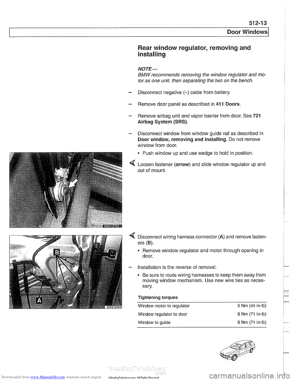
Loosen fastener (arrow) and slide window regulator up and
out of mount.
Disconnect wiring harness connector (A) and remove fasten-
ers
(6).
Remove window regulator and motor through opening in
door.
- Installation is the reverse of removal.
Be sure to route wiring harnesses to keep them away from
moving window mechanism. Use new wire ties as neces-
sary.
Tightening torques
Window motor to regulator
5 Nrn (44 in-ib)
Window regulator to door
Window to guide
8 Nrn (71 in-lb)
8 Nrn (71 in-lb)
Page 880 of 1002
Downloaded from www.Manualslib.com manuals search engine
I lnterior Trim
This repair group covers interior trim removal and installation
procedures.
- Refer to the following repair groups for additional information:
250 Gearshift Linkage
41 1 Doors (interior door panels)
@ 612 Switches
620 Instruments
640 Heating and Air Conditioning [IHKA control panel!
650 Radio
721 Airbag System (SRS)
lnterior trim repairs
lnterior trim and finish panels are clipped or screwed into
place. Many of the trim retaining clips are designed
to be used
only once. When removing trim that is held in place with clips,
it is a good idea to have spare clips on hand before beginning
the job.
WARNING-
Special precautions must be observed when servicing the
BMWSupplementai Restraint System (SRS). Serious inju-
ry may result if system service is attempted by persons un-
familiar with the BMW
SRS and its approved service
procedures. BMW
speciiies that all inspection and service
should be performed by an authorized BMW
dealer.
Before performing any work involving airbags, discon-
nect the negative
() battery cable. See 721 Airbag
System (SRS).
Airbags contain a back-uppowersupply within the SRS
control module. A
5 second discharge period should be
allowed after the battery cable has been disconnected.
CAUTION-
* When working on electrical switclies or lights, always dis-
connect the negative
(-) cable from the battery and insu-
late the cable end to prevent accidental reconnection.
a Prior to disconnecting the battery, read the battery dis-
connection cautions given in
W1 General Warnings
and Cautions.
To prevent marring the trim when working on interior
components, work with plastic prying
tools or wrap the
tips of screwdrivers and pliers with tape before prying
Page 898 of 1002
Downloaded from www.Manualslib.com manuals search engine
51 5-4
I Central Locking and Anti-Theft
Driver's door lock
The
lock/unlock signals are sent as input to the door module
from two microswitches on the lockcylinder. The driver's door
module carries out the locking
/ unlocking functions of the
driver's door through its final stage control.
The signal to lock the remaining doors, trunk or tailgate and
fuel flap is sent over the P-Bus to the GM and the passenger
door module. Activation of the passengers door
loclt is carried
out by the passenger door module. The rear doors, trunlt or
tailgate and fuel flap are
locked by the f~nal stage in the GM.
When
locked from the outside, all doors are set to the double
lock position and the GM will not carry out any unlock com-
mands from the central
loclc button or remote trunk release
button.
Selective unlocking
When unlocking with the key or the remote transmitter, the
first unloclcrequestwill only unlock the driver'sdoor. A second
unlock request will unlock the remaining doors, trunk or tail-
gate and fuel flap.
Trunk locking
I
The vehicle can be locked/unlocked from the trunlc loclc cylin-
der. The GM locks the trunk or tailgate, rear doors and fuel fill-
er. The locking command is passed over the P-Bus to the
respective door modules to lock the driver's and passengers
doors.
Locking the trunk and removing the key in the
hor~zontal posi-
tion will set the valet lock and prevent opening of the trunlt
with the central locking system.
Central locking switch
-
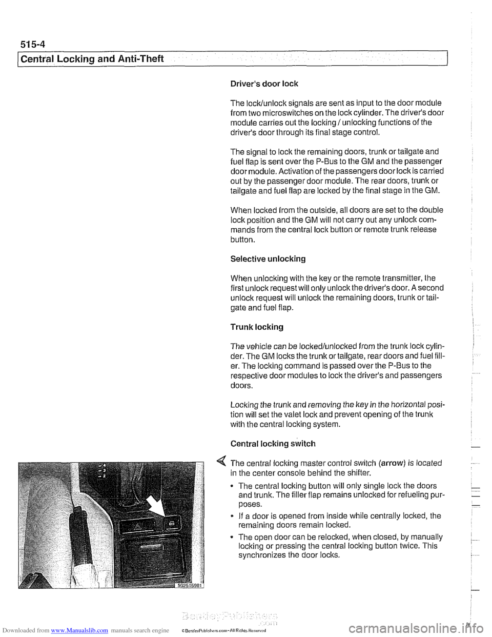
< The central locking master control switch (arrow) is located
in the center console behind the shifter.
The central locking button will only single
loclt the doors
and trunk. The filler flap remains unloclted for refueling pur-
poses.
If a door is opened from inside while centrally locked, the
remaining doors remain locked.
The open door can be relocked, when closed, by manually
locking or pressing the central locking button twice. This
synchronizes the door
locks.
Page 899 of 1002
Downloaded from www.Manualslib.com manuals search engine
Central Locking and Anti-Theft
DWA alarm
The DWA alarm system is
armedldisarmed when thevehicle
is locked / unlocked from either the door or trunk.
Convenience closing
I opening
The windows and sun roof can be closed or opened by hold-
ing the key in the
loclc I unlock position.
Crash sensor
The crash sensor is located in the left front
kick panel. It func-
tions by unlocking all doors in the event of an accident.
NOTE-
Continuous and repeated locliing / unlocking may cause
timedarrest of
the locliing system. When activated, the timed
arrest lasts for two minutes. The timed arrest does not affect
the crash sensor
unlocliing the doors in case of an accident.
Door locks
The driver's door lock location is the only point outside of the
vehicle where the ltey can mechanically control all of the cen-
tral locking system functions.
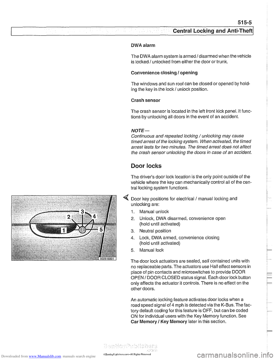
4 Door key positions for electrical / manual loclting and
unlocking are:
1. Manual unlock
2. Unlock, DWA disarmed, convenience open
(hold until activated)
3. Neutral position
4. Lock, DWA armed, convenience closing
(hold until activated)
5. Manual lock
The door lock actuators are sealed. self contained units with
no replaceable parts. The
actuators use Hall effect sensors in
place of pin contacts and microswitches to provide DOOR
OPEN
I DOOR CLOSED status signal. Each door lock button
only affects the actuator it controls. There is no effect on the
other doors.
An automatic locking feature activates door locks when a
road speed signal of 4 mph is detected via the K-Bus. The fac-
tory default coding for this feature is OFF, but can be coded
ON for individual users with the Key Memoryfunction. See
Car Memory
1 Key Memory later in this section.
Page 900 of 1002
Downloaded from www.Manualslib.com manuals search engine
51 5-6
(Central Locking and Anti-Theft
Each rear door is equipped with the child lock-out lever, pre-
venting the door from being opened from the inside regard-
less of loclc button position.
Starting with models produced afler
911997, the General
Module and electronic immobilizer (EWS) interface via the
K-
Bus to monitor double lock status and to initiate double loclc
override. This feature allows the doors to be opened from the
inside if a key accepted by EWS is switched on in the ignition.
See Single lock and double lock function.
The door loclc buttons are mechanically uncoupled from the
actuators when locked. The remote keyless entry system
(FZV) is standard equipment. This allows for elimination of
the passengers side door
loclt cylinder.
Another function of the locking system is the
sofl close trunk
(SCA) system, where applicable.
Single lock and double lock function
(2000 and later models)
On models produced after
911999, each door lock actuator in-
corporates two motors:
Single lock motor controls the mechanical loclc mechanism
when the central lock switch is pressed to single loclc the
vehicle. The loclc mechanism is fully locked at this point but
can stil. be openeo from
the interor by pulng the appropri-
are interior door nandle lwce or by pressing rhe central
lock switch again. When single
lock'function is activated,
the fuel filler flap actuator is not locked.
Double lock motor, also known as central arrest, is activat-
ed only when the vehicle is locked from the outside at the
driver's door lock with a key or when the GM receives a
lock request from the remote entry (FZV) system. In this
case the double lock motor is activated simultaneously
with the single lock motor. The function of the double loclc
motor is to mechanically offset an internal rod in the loclc
actuator, disabling it from unlocking the vehicle from the in-
terior. This prevents the doors from being unloclted by any
means except from an unlock request at the driver's door
or via the FZV remote key.
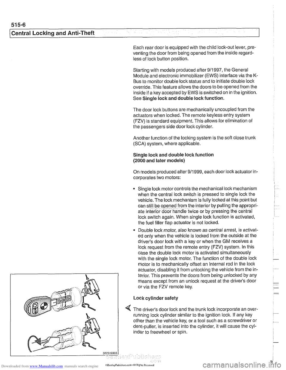
Lock cylinder safety
4 The driver's door loclc and the trunk loclc incorporate an over-
running loclc cylinder similar to the ignition lock. If any key
other than the vehicle key, or a tool such as a screwdriver or
dent-puller, is inserted into the cylinder, it will cause the cyl-
inder to freewheel or spin.
Page 901 of 1002
Downloaded from www.Manualslib.com manuals search engine
Central Locking and Anti-Theft
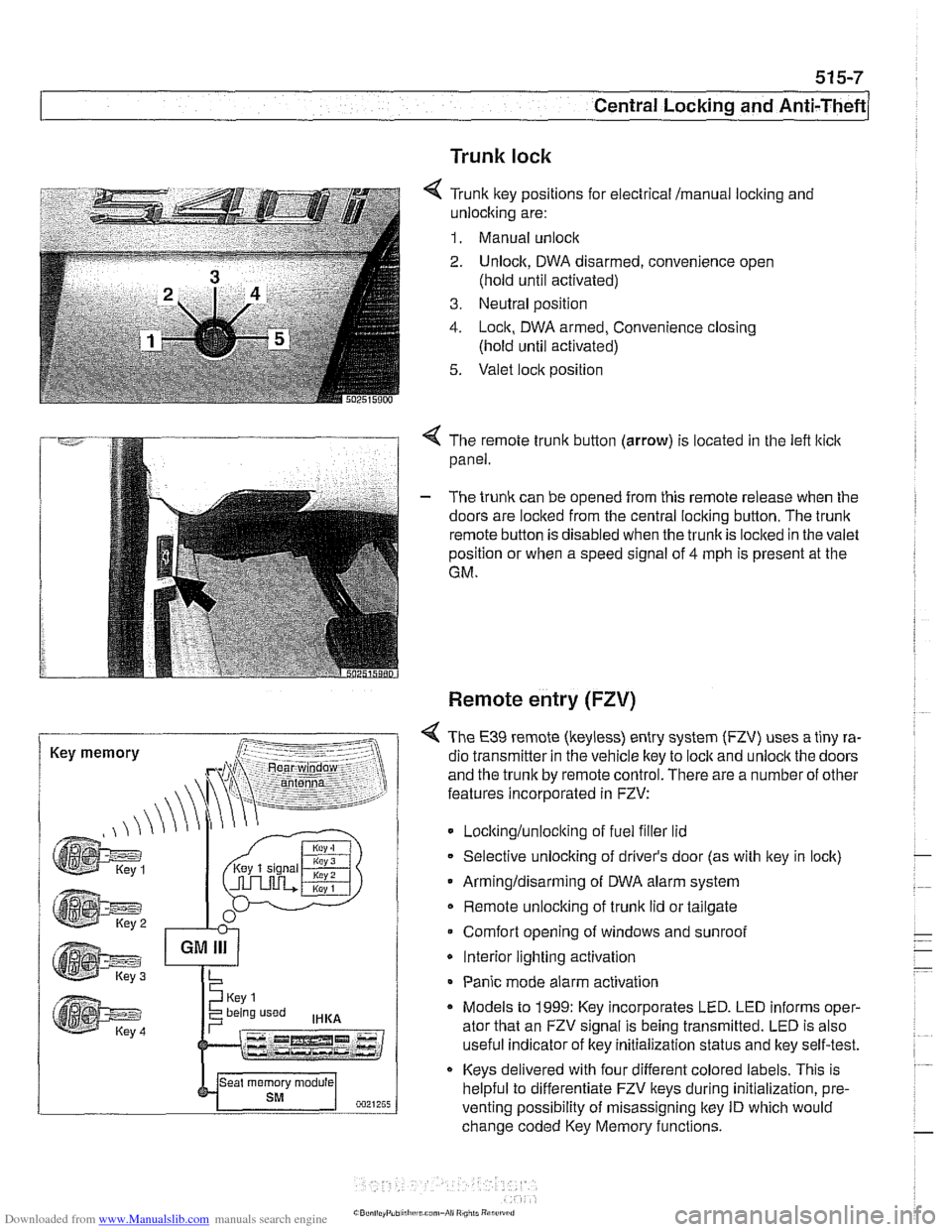
Trunk lock
6 Tr~nk ftey pos~rions for eecir'cal mama, locking and
-nlock~ng are:
1. Manual unock .. - - - ........ - ..- .- ................. s.=.=-- 2. Unlock. DWA oisarmed, conven:ence open
(nold
un1:l aclivaledj
3. Ne~tral posit'on
1. -ocn. DWA armeo, Convenience closng
(hold ~nti activated)
5. Valet .oc,t position
. -- .............-... .- . - -.....
Key memory
< The remote trunk button (arrow) is located in the lefl lticlc
panel.
- The trunk can be opened from this remote release when the
doors are locked from the central locking button. The
trunk
remote button is disabled when the trunkis loclted in the valet
position or when a speed signal of
4 mph is present at the
GM.
Remote entry (FZV)
< The €39 remote (keyless) entry system (FZV) uses a tiny ra-
dio transmitter in the vehicle key to
lock and unlock the doors
and the trunk by remote control. There are a number of other
features incorporated in FZV:
Locltinglunloclting of fuel filler lid
Selective unlocking of driver's door (as with key in lock)
Armingldisarming of DWA alarm system
Remote unlocking of
trunk lid or tailgate
Comfort opening of windows and sunroof
* Interior lighting activation
Panic mode alarm activation
* Models to 1999: Key incorporates LED. LED informs oper-
ator that an FZV signal is being transmitted. LED is also
useful indicator of key initialization status and lkey self-test.
Keys delivered with four different colored labels. This is
helpful to differentiate FZV keys during initialization,
pre.
venting possibility of misassigning key ID which would
change coded Key Memory functions.
Page 902 of 1002
Downloaded from www.Manualslib.com manuals search engine
515-8
/Central Locking and Anti-Theft
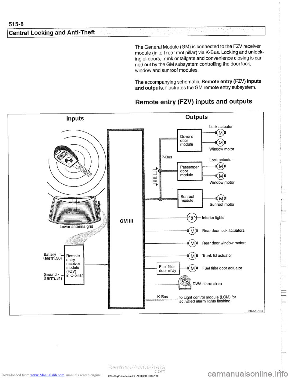
The General Module (GM) is connected to the FZV receiver
module (in left rear roof pillar) via K-Bus. Locking and unlock-
ing of doors, trunk or tailgate and convenience closing is car-
ried out by the GM subsystem controlling the door lock,
window and sunroof modules.
The accompanying schematic, Remote entry
(FZV) inputs
and outputs, illustrates the GM remote entry subsystem.
Remote entry (FZV) inputs and outputs
Inputs Outputs