bumper BMW 528i 2000 E39 Owner's Manual
[x] Cancel search | Manufacturer: BMW, Model Year: 2000, Model line: 528i, Model: BMW 528i 2000 E39Pages: 1002
Page 860 of 1002
Downloaded from www.Manualslib.com manuals search engine
51 0-1 0
Exterior Trim, Bumpers Rear bumper, removing
and installing
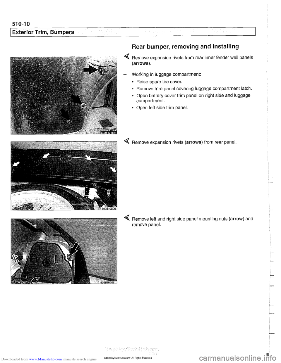
Remove expansion rivets from rear inner fender well panels
(arrows).
Working in luggage compartment:
Raise spare tire cover.
- Remove trim panel covering luggage compartment latch.
Open battery cover trim panel on right side and luggage
compartment.
Open left side trim panel.
4 Remove expansion rivets (arrows) from rear panel.
Remove left and
remove panel. right
side panel mounting
nuts (arrow) and
Page 861 of 1002
Downloaded from www.Manualslib.com manuals search engine
Exterior Trim, Bumpers
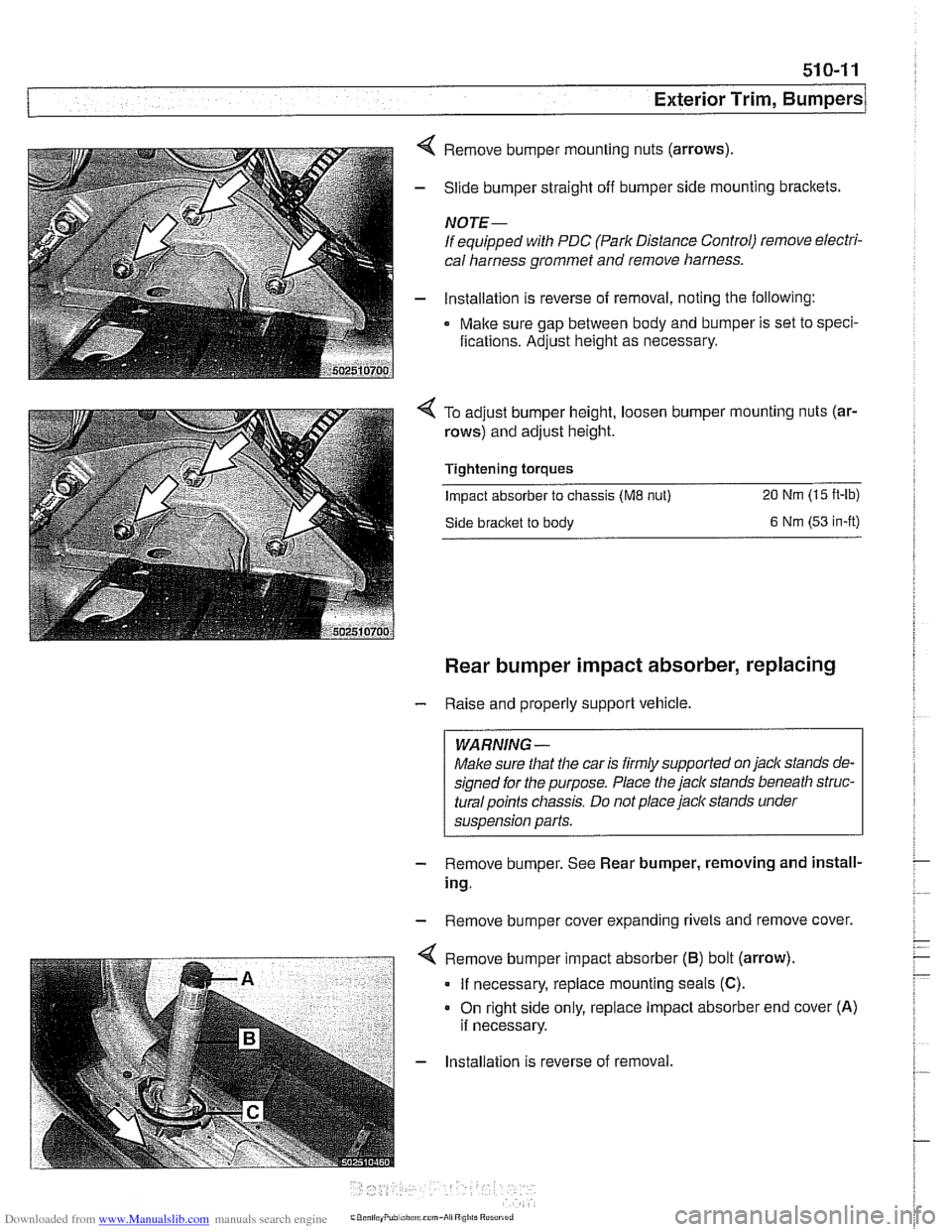
4 Remove bumper mounting nuts (arrows)
- Slide bumper straight off bumper side mounting brackets.
NOTE-
If equipped with PDC (Park Distance Control) remove electri-
cal harness grommet and remove harness.
- lnstallation is reverse of removal, noting the following:
Make sure gap between body and bumper is set to speci-
fications. Adjust height as necessary.
To adjust bumper height, loosen bumper mounting nuts (ar-
rows) and adjust height.
Tightening torques
Impact absorber to chassis (ME nut) 20 Nm (15 ft-lb)
Side bracket to body 6 Nm (53 in-it)
Rear bumper impact absorber, replacing
- Raise and properly support vehicle.
WARNING -
Make sure that the car is firmly supported on jack stands de-
signed for the purpose. Place the jack stands beneath
struc-
turalpoints chassis. Do not place jaclc stands under
suspension parts.
- Remove bumper. See Rear bumper, removing and install-
ing.
- Remove bumper cover expanding rivets and remove cover.
. - . . - . . ".-- < Remove b~mper mpact absorber (6) bot (arrow).
I If necessary, replace mounting seals (C).
- Installation is reverse of removal.
Page 862 of 1002
Downloaded from www.Manualslib.com manuals search engine
I Exterior Trim, Bumpers
Tightening torques Impact absorber to chassis
(M8 nut) 20 Nm (15 ft-lb)
Impact absorber to chassis
(M6 nut) 9 Nm (80 In-lb
Bumper bracket to impact absorber 45 Nm (32 ft-lb)
(MI0 bolt)
Front bumper height, adjusting
- A 14 mm allen socket is needed to make adjustments
- Raise and properly support vehicle.
WARNING-
Make sure that the car is firmly supported on jackstands de-
signed for the purpose. Place the jack stands beneath a
structural chassis point.
Do not place jack stands under sus-
pension parts.
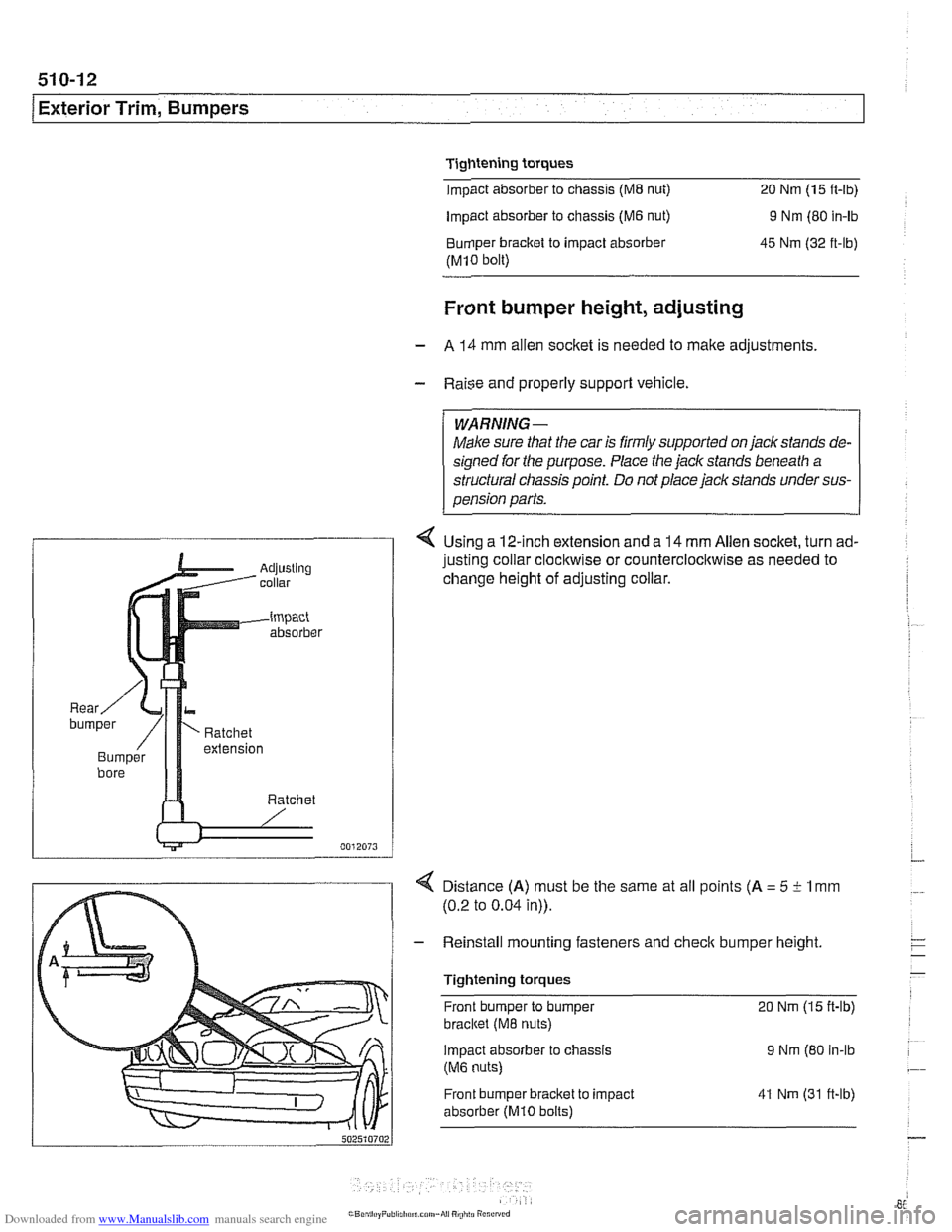
4 Using a 12-inch extension and a 14 mm Allen socket, turn ad-
justing collar
clocl~wise or counterclocl~wise as needed to
change height of adjusting collar.
4 Distance (A) must be the same at all points (A = 5 i- 1 mm
(0.2 to 0.04 in)).
- Reinstall mounting fasteners and check bumper height
Tightening torques Front bumper to bumper
20 Nm (15 ft-lb)
bracltet (M8 nuts)
Impact absorber
to chassis 9 Nm (80 in-lb
(M6 nuts)
Front bumper bracket to impact
absorber
(MI0 bolts)
41 Nm (31 ft-lb)
Page 863 of 1002
Downloaded from www.Manualslib.com manuals search engine
51 0-1 3
Exterior Trim, Bumpers
Exterior trim is attached to the body with plastic clips and fas-
teners that may be damaged during removal. Be sure to have
necessary fasteners on hand when reinstalling exterior trim
pieces.
BMW emblem, removing and installing
The procedure given below applies to both front and rear
emblems.
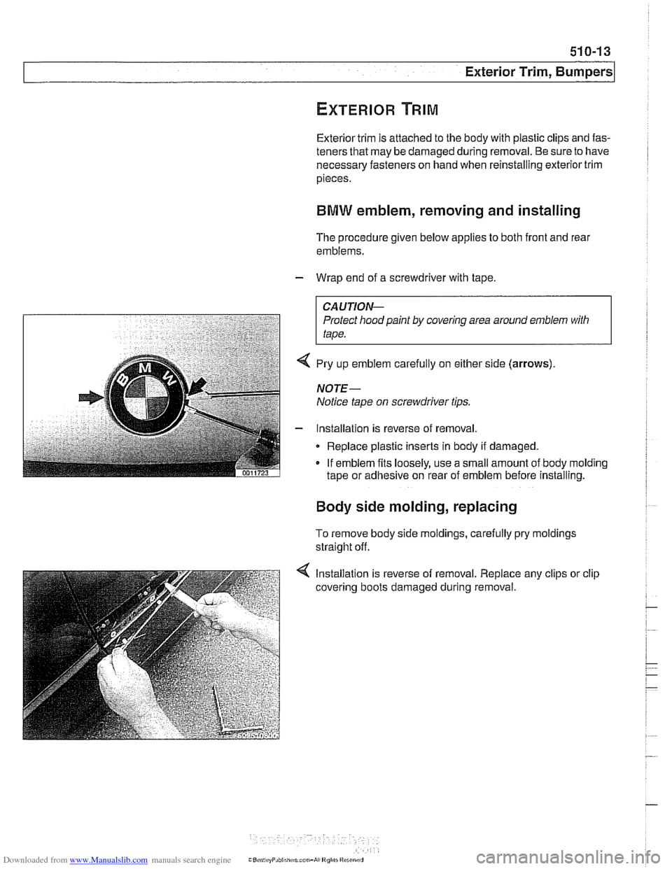
- Wrap end of a screwdriver with tape.
CAUTION-
Protect hood paint by covering area around emblem with
tape.
4 Pry up emblem carefully on either side (arrows)
NOTE-
Notice tape on screwdriver tips.
- Installation is reverse of removal
Replace plastic inserts in body if damaged.
If emblem fits loosely, use a small amount of body molding
tape or adhesive on rear of emblem before installing.
Body side molding, replacing
To remove body side moldings, carefully pry moldings
straight off.
4 Installation is reverse of removal. Replace any clips or clip
covering boots damaged during removal.
Page 864 of 1002
Downloaded from www.Manualslib.com manuals search engine
Exterior Trim, Bumpers 1
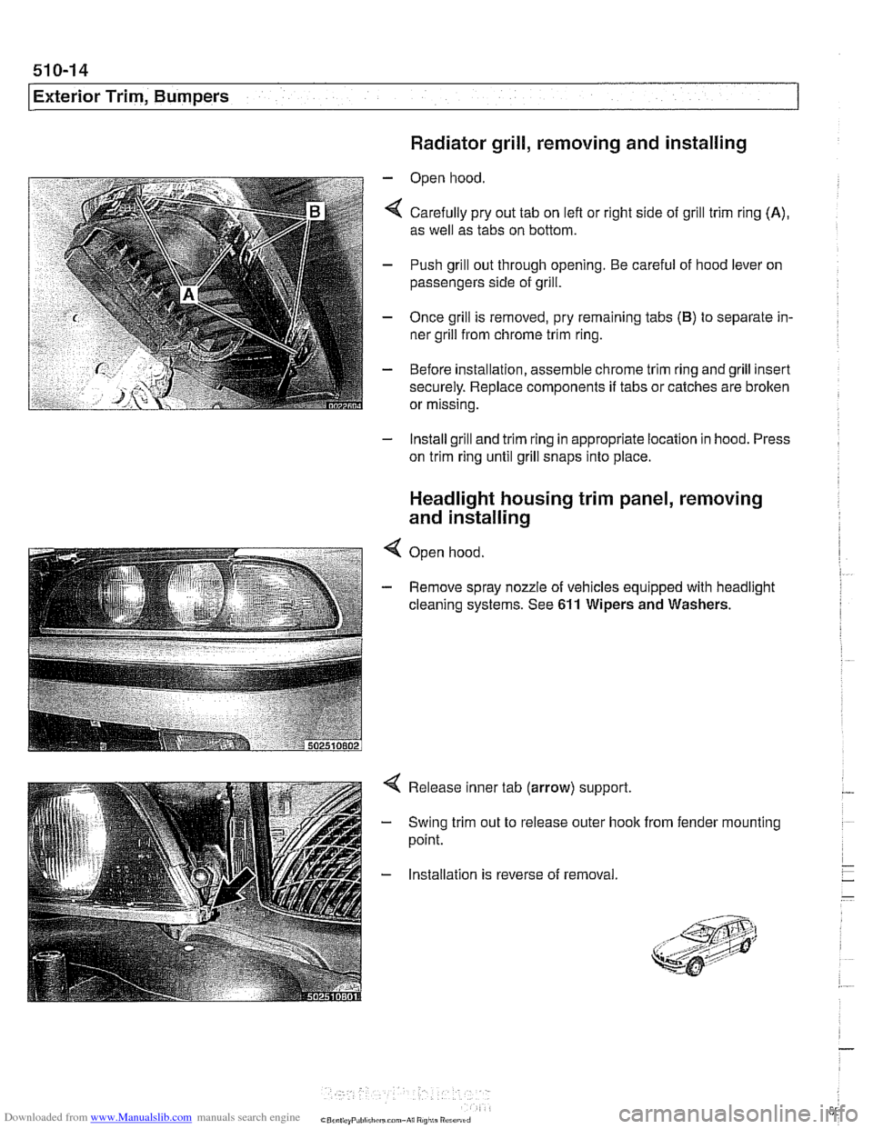
Radiator grill, removing and installing
- Open hood
4 Carefully pry out tab on lefl or right side of grill trim ring (A),
as well as tabs on bottom.
- Push grill out through opening. Be careful of hood lever on
passengers side of grill.
- Once grill is removed, pry remaining tabs (B) to separate in-
ner grill from chrome trim ring.
- Before installation, assemble chrome trim ring and grill insert
securely. Replace components
if tabs or catches are brolten
or missing.
- Install grill and trim ring in appropriate location in hood. Press
on trim ring until grill snaps into place.
Headlight housing trim panel, removing
and installing
4 Open hood
- Remove spray nozzle of vehicles equipped with headlight
cleaning systems. See
611 Wipers and Washers.
Release inner tab (arrow) support.
Swing trim out to release outer hook
point. from fender mounting
Installation is reverse of removal
Page 940 of 1002
Downloaded from www.Manualslib.com manuals search engine
I Seat Belts
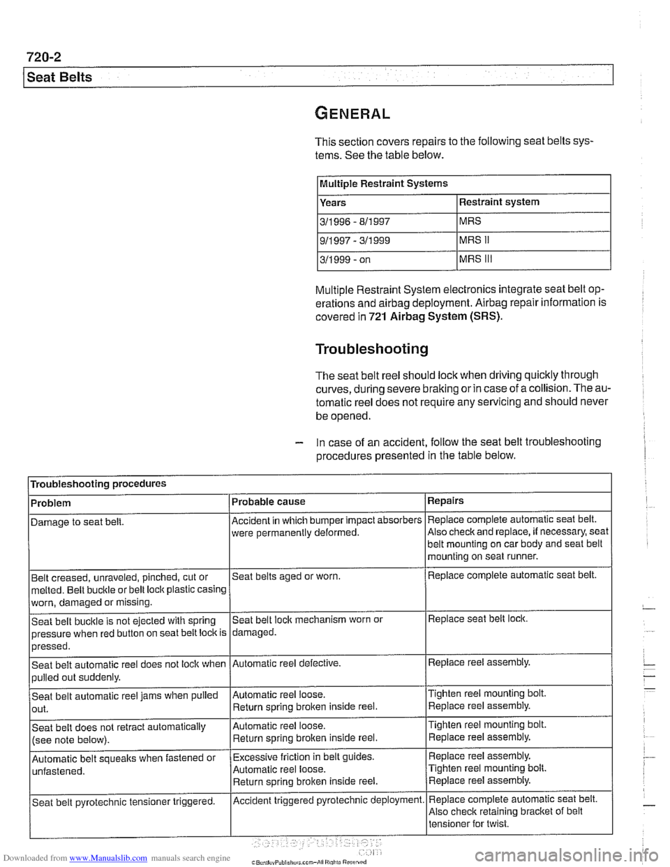
This section covers repairs to the following seat belts sys-
tems. See the table below.
IMultIple Restraint Systems I
Years
311 996 - 811 997
Multiple Restraint System electronics integrate seat belt op-
erations and
airbag deployment. Airbag repair information is
covered
in 721 Airbag System (SRS).
Troubleshooting
The seat belt reel should lock when driving quicltly through
curves,
during severe braking or in case of a collision. The au-
tomatic reel does not require any servicing and should never
be opened.
- In case of an accident, follow the seat belt troubleshooting
procedures presented
in the table below.
Troubleshooting procedures
Belt creased, unraveled, pinched, cut or
melted. Belt buckle or belt loclt plastic casing Repairs
Replace complete automatic
seat belt.
Also
checlt and replace, if necessary, seat
Problem
Damage to seat
belt.
worn, damaged or missing.
Seat belt bucltle is not ejected with spring
pressure when red button on seat belt loclt is
>--- I I
Automatic belt soueaks when fastened or I~xcessive friction in belt guides. I Replace reel assembly.
Probable
cause
Accident in which bumper impact absorbers
were permanently deformed.
Seat belts aged or worn.
pressed.
Seat belt automatic reel does not lock when
pulled out suddenly.
Seat belt automatic reel jams when pulled
out.
Seat belt does not retract automatically
(see note below).
Automatic reel loose. Return sorino broken inside reel. belt mounting on car body and
seat belt
mounting on seat runner.
Replace complete automatic seat belt.
Seat belt
loclt mechanism worn or
damaged.
Tighten reel mounting bolt Replace reel assembly.
Replace seat belt lock.
Automatic reel defective.
Automatic reel loose. Return spring
broken inside reel.
Automatic reel loose.
Return spring brolten inside reel. Replace reel
assembly.
Tighten reel mounting
bolt.
Replace reel assembly.
Tighten reel mounting bolt. Replace reel assembly.
~ ~-~~ , - I'
Replace complete automatic seat belt.
Also check retaining bracket of belt
Seat belt
pyrotechnic tensioner triggered. Accident triggered pyrotechnic deployment.
Page 992 of 1002
Downloaded from www.Manualslib.com manuals search engine
2 INDEX
Battery, starter, alternator
alternator (generator)
121-10
6-cylinder engine, removingi
installing 121-15
M62 engine 121-16
M62 TU engine (water cooled)
121-18
battery
121-5 charging 121-9
safety terminal 121-3
testing 121-5 charging system, troubleshooting
121-12
starter
121-1 9
6-cylinder engine, removingi instaliinq 121-20 . V-8 engine, rernovinglinsialiing
121-21
solenoid, removinglinstalling
121-23 troubleshooting 121-19
see also Maintenance
Bearing, wheel
see Front suspension
see also Rear suspension
Belts see Maintenance, drive belts
Blade, wiper
see Wipers and Washers
Blower motor see
A/C
BMW emblem
see Exterior trim
BMW special tools 010-18 see also special tools section at
beginning
of each repair group
Body dimensions 400-2
interior features
400-9 salety and security 400-7
Body side molding
see Exterior trim
Bonnet see Engine hood
Boot see Trunk
Brake fluid
020-24, 340-8
Brake fluid pressure sensor
340-30
Brakes
ABS, ASC or DSC system
300-12
component replacement 340-26
ASCIDSC switch
see Switches
bleeding
bralces 340-8
brake booster 340-1 9 bralce Dads. caiioers and rotors ,., 340-1 1
descriotion 300-10
e~ectrdnic brake & stability 300-11
light switch
see Switches
master cylinder
340-16 pariking brake 340-22
troubleshooting 340-5
Bulbs see Lights
Bumper
lront 510-6 height, adjusting 510-12
rear 510-9
Bus system
600-4
Camber
320-33
Camshaft
removingiinslaiiing
M52 engine 116-12
M52 TU
/ M54 engine 116-1 9 M62 engine 11 6-39
wear
116-6
Camshaft position sensors
see ignition system
Camshaft timing chain
adjusting M52 engine
117-22
M52 TU I M54 engine 117-43
M62 engine 117-79 removinglinstalling
M52 engine 117-26
M52TU 1 M54 engine 113-46.116-
28
M62 engine 117-66
Capacities, fluid
020.10
Car rnemorvlicev memorv . . 600-10
see also Centrai
lociking
Carbon canister, activated
see Fuel
tank
Caster
320-33
Catalytic converter and oxygen sensor 020-19
see also Exhaust system: exhaust
manilolds
Cautions
001-3
CD changer
650-4
Center bearing, driveshaft
see Driveshait
Center brake light
sedan
630-13
Center console
513-3
Centrai body electronics (ZKE 111)
600-6
Central locking
car memoryiey memory 515.12 general module iunctions 515-2
remote entry (FZV) 515-8
remote lkey initialization 515-10 single lociddouble ioclk 515-6
switch 515-4
Chain
see Camshaft liming chain
Characteristic map (electrically heated) thermostat
see Electrically heated thermostat
Charging system
see Battery, starter, alternator
Cluster see instruments
Clutch fluid see Maintenance
hydraulics
210-4
mechanical 210-9
switch
see Switches, pedal ciuster
variations
210.10
Codes, fault OED-1
Coil
see Ignition system
Coil spring
see Front suspension
see also Rear
suspe nsion