under car shield BMW 528i 2000 E39 Owner's Manual
[x] Cancel search | Manufacturer: BMW, Model Year: 2000, Model line: 528i, Model: BMW 528i 2000 E39Pages: 1002
Page 683 of 1002
Downloaded from www.Manualslib.com manuals search engine
Steering and Wheel ~li~nrnentl
Steering gearbox, removing and installing
- Disconnect negative (-) battery cable. See 020 Mainte-
nance.
CAUTION-
Prior to disconnecting the battew read the battery discon-
nection cautions given in
001 General Cautions and
Warnings.
- Remove airbag unit from steering wheel. See 721 Airbag
System (SRS).
WARNING -
Improper handling of the airbag could cause serious injury
Store the
airbag with the horn pad facing up. If stored lacing
down, accidental deployment couldpropel it violently info the
air, causing
injuv
- Remove steering wheel as described earlier.
- Drain power steering system reservoir.
- Raise front of car.
WARNING -
Make sure the car is firmly supported on jack stands de-
signed for the purpose. Place jack stands beneath structural
chassis points. Do not place jack stands under suspension
Darts.
- Remove heat shield from left side of subframe.
- Remove fluid hoses from top of steering gearbox. Immedi-
ately plug all fluid openings.
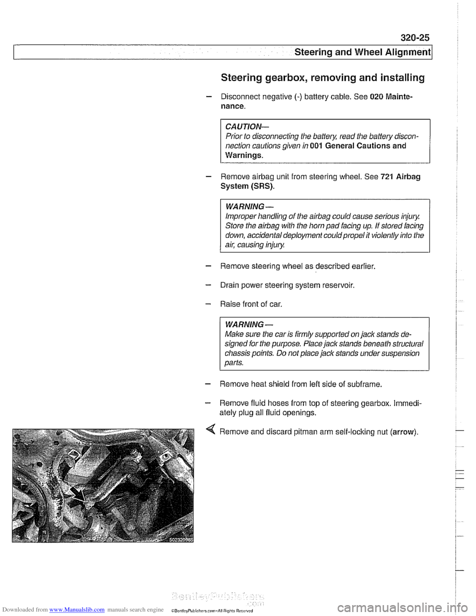
Remove and discard
pitman arm self-loclting nut (arrow).
Page 686 of 1002
Downloaded from www.Manualslib.com manuals search engine
320-28
[steering and Wheel Alignment
Pitman arm, removing and installing
- Raise front of car. Remove splash shield from under engine.
Male sure the car is
firmly supported on jack stands de-
signed for the purpose. Place jack stands beneath structural
chassis points. Do not place
jaclc stands under suspension
parts.
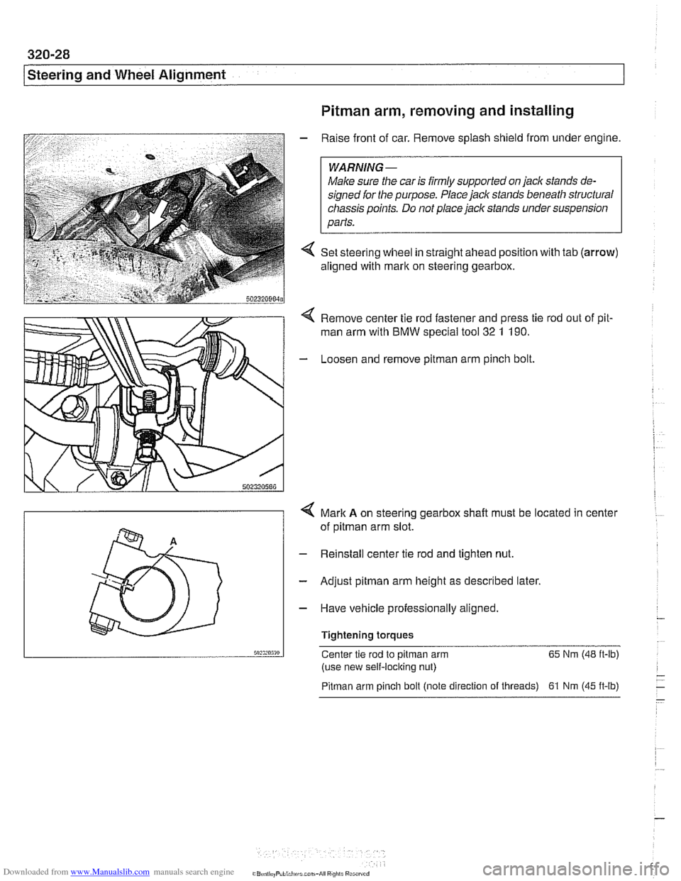
4 Set steering wheel in straight ahead position with tab (arrow)
aligned with mark on steering gearbox.
Remove center tie rod fastener and press tie rod out of pit.
man arm with BMW special
too1 32 1 190.
- Loosen and remove pitman arm pinch bolt
4 Mark A on steering gearbox shalt must be located in center
of
pitman arm slot.
- Reinstall center tie rod and tighten nut.
- Adjust pitman arm height as described later.
- Have vehicle professionally aligned.
Tightening torques
50:s,n5m Center tie rod to pitman arm 65
Nm (48 ft-lb)
(use new self-locking nut)
Pitman arm pinch bolt (note direction of threads) 61 Nrn (45 ft-lb)
Page 687 of 1002
Downloaded from www.Manualslib.com manuals search engine
Steering and Wheel Alignment
Pitman arm, adjusting
As the vehicle suspension settles down, the toe on the left
and right wheels must remain identical for proper handling.
By adjusting the height of the
pitman arm, the left and right tie
rods are moved to the same ride level setting. This will opti-
mize straight-ahead travel on uneven road surfaces.
- Raise front of car. Remove splash shield from under engine.
WARNING-
Male sure the car is iirmly supported on jack stands de-
signed ior the purpose. Place jack stands beneath structural
chassis points. Do not place
jaclc stands under suspension
parts.
- Remove bolts from left and right inner control arm mounts.
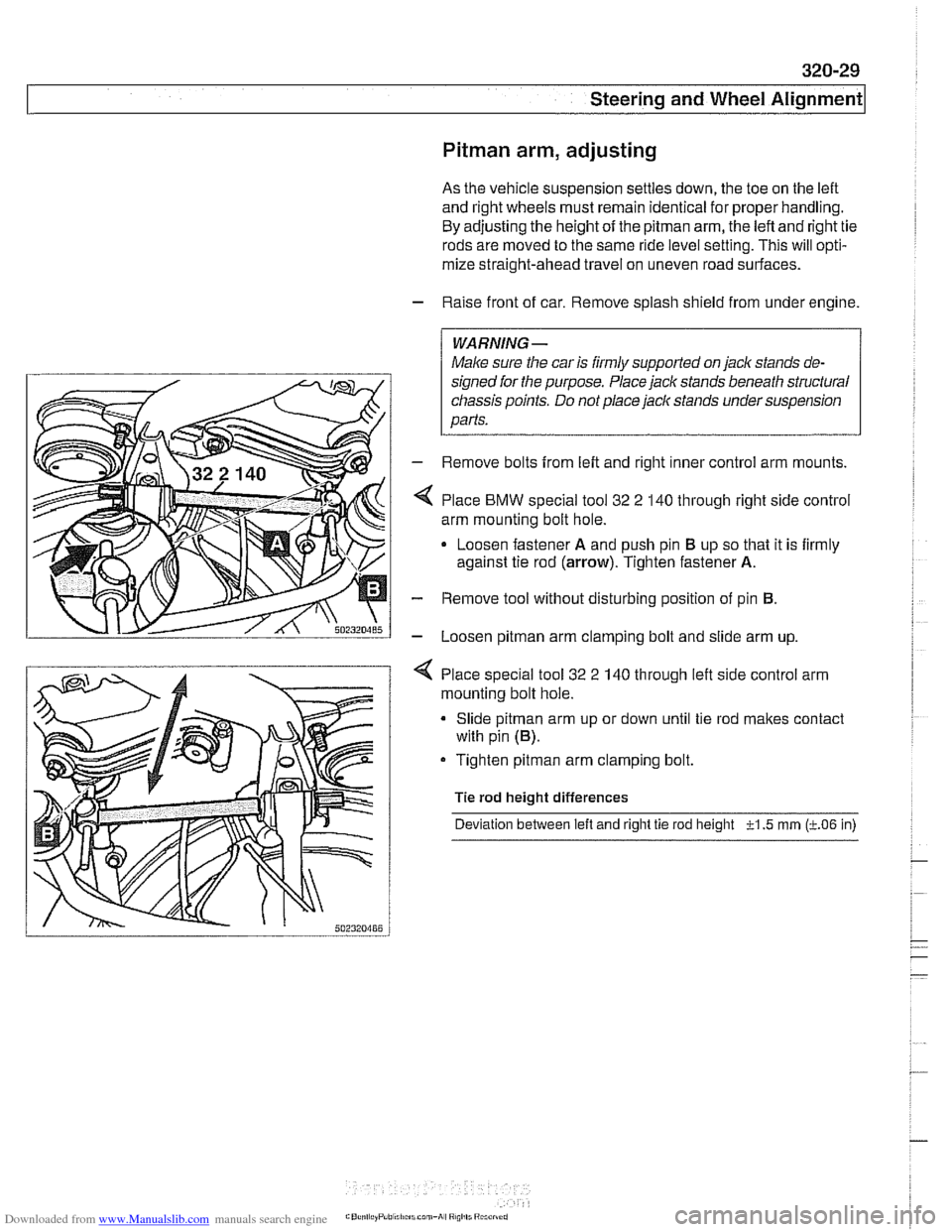
Place
BMW special tool 32 2 140 through right side control
arm mounting bolt hole.
Loosen fastener
A and push pin El up so that it is firmly
against tie rod
(arrow). Tighten fastener A.
- Remove tool without disturbing position of pin El.
- Loosen pitman arm clamping bolt and slide arm up.
4 Place special tool 32 2 140 through left side control arm
mounting bolt hole.
Slide
pitman arm up or down until tie rod makes contact
with pin
(El).
Tighten pitman arm clamping bolt.
Tie rod height differences
Deviation between
left and right tie rod height -?-I .5 rnrn (LO6 in)
Page 688 of 1002
Downloaded from www.Manualslib.com manuals search engine
I Steering and Wheel Alignment
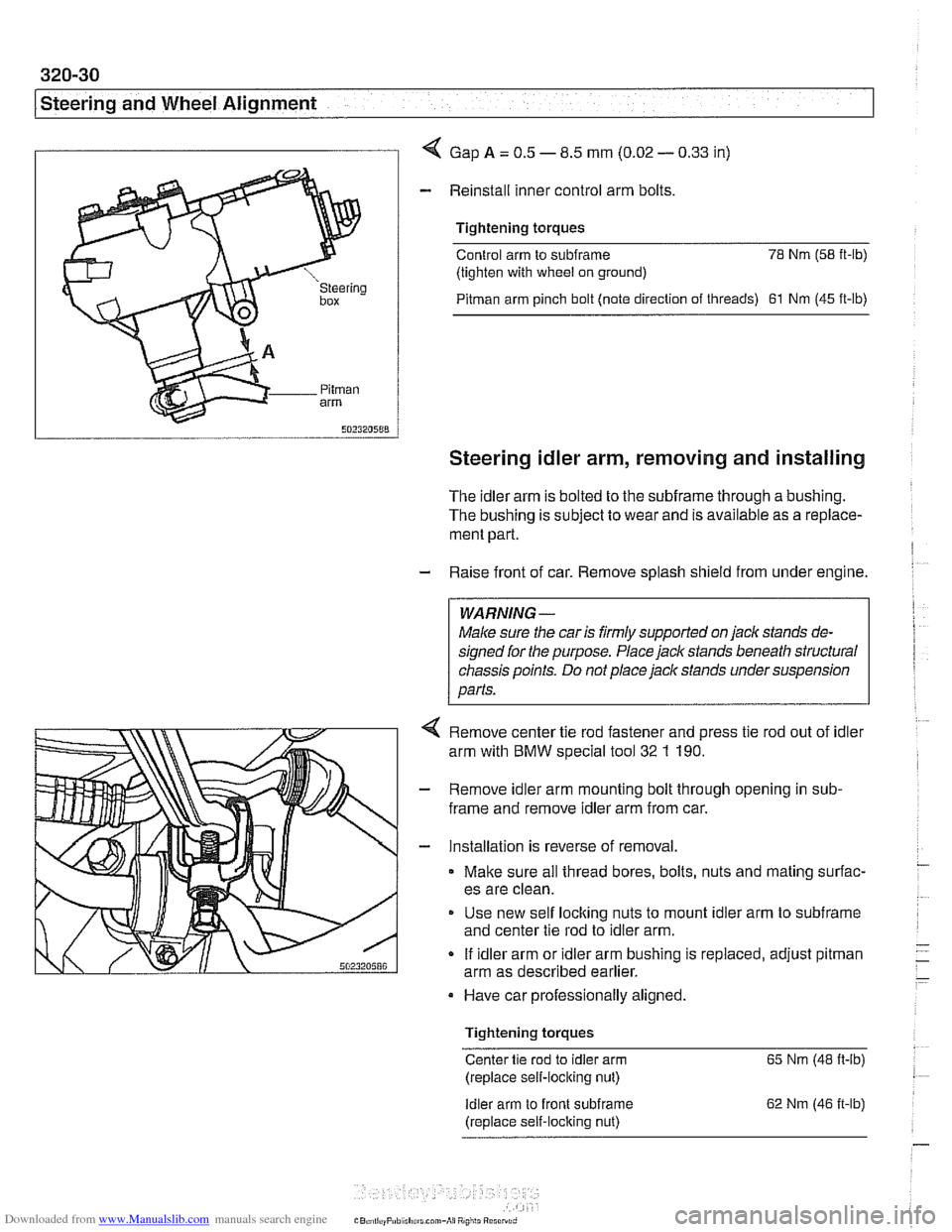
I I 4 Gap A = 0.5 - 8.5 mm (0.02 - 0.33 in)
- Reinstall inner control arm bolts
Tightening torques
Control arm to
subframe 78 Nm (58 it-lb)
(tighten with wheel on ground)
Pitman arm pinch bolt (note direction of threads) 61 Nm (45 ft-lb)
Steering idler arm, removing and installing
The idler arm is bolted to the subframe through a bushing.
The bushing is subject to wear and is available as a replace-
ment part.
- Raise front of car. Remove splash shield from under engine.
WARNING -
Male sure the car is firmly supported on jaclc stands de-
signed for the purpose. Place jack stands beneath structural
chassis points. Do not place jack stands under suspension
parts.
4 Remove center tie rod fastener and press tie rod out of idler
arm with
BMW special tool 32 1 190.
- Remove idler arm mounting bolt through opening in sub-
frame and remove idler arm from car.
- Installation is reverse of removal.
Make sure all thread bores, bolts, nuts and mating surfac-
es are clean.
Use new self
loclting nuts to mount idler arm to subframe
and center tie rod to idler arm.
If idler arm or idler arm bushing is replaced, adjust
pitman
arm as described earlier.
Have car professionally aligned.
Tightening torques
Center tie rod to idler arm 65 Nm (48 ft-ib)
(replace self-locking nut)
Idler arm to front subirame
(replace self-locking nut) 62
Nm (46 it-lb)
Page 690 of 1002
Downloaded from www.Manualslib.com manuals search engine
320-32
Steering and Wheel Alignment
Center tie
rod, replacing
- Raise front of car. Remove splash shield from under engine.
WARNING-
Make sure tlie car is firmly supported on jack stands de-
signed for the purpose. Place jack stands beneath structural
cliassis points. Do not place jack stands under suspension
parts.
- Measure length of left and right (outer) tie rods. Write down
measurements.
NOTE-
Accurate measurement of the tie rod end with reference to
the center tie rod will help approximate correct wheel align-
ment when new parts are installed.
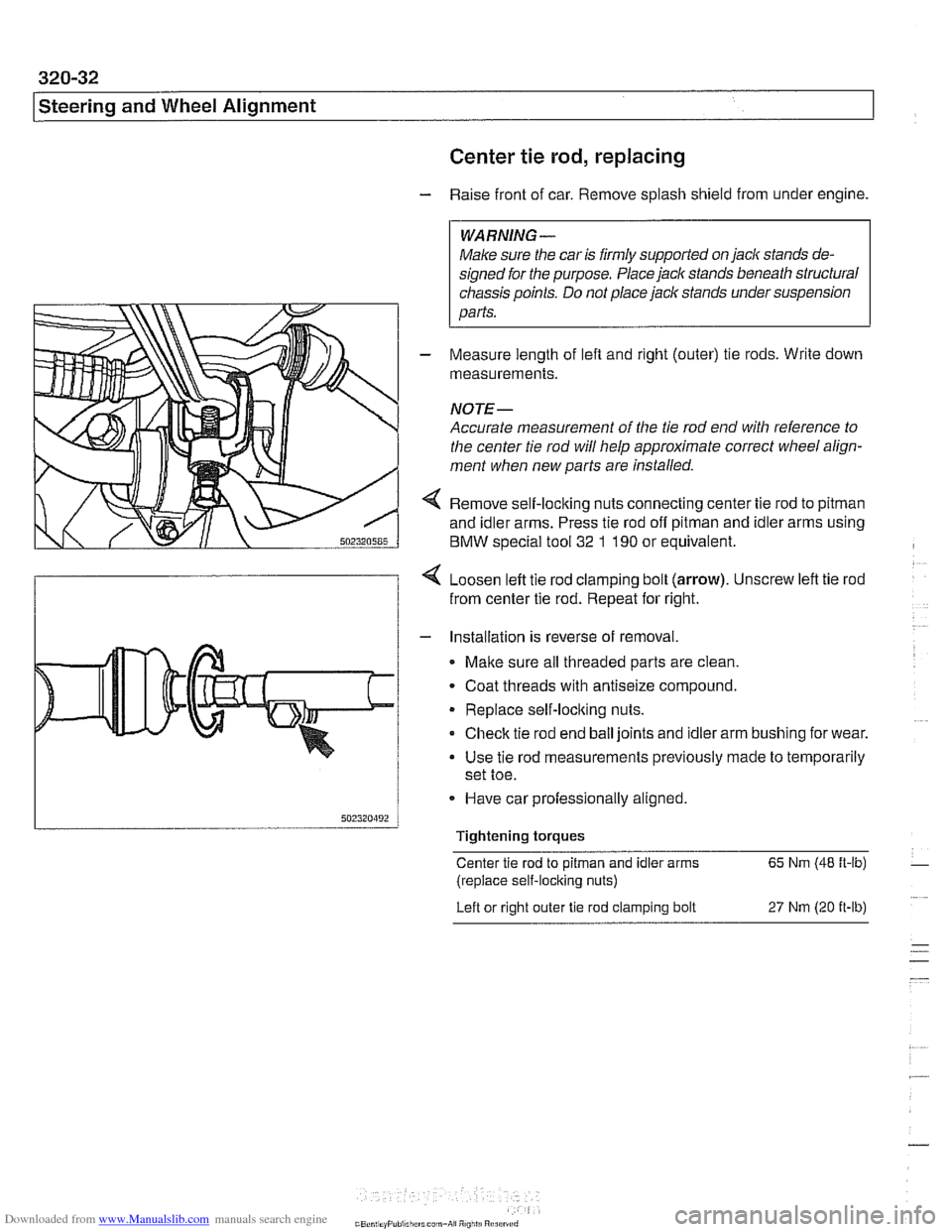
4 Remove self-loclting nuts connecting center tie rod to pitman
and idler arms. Press tie rod off pitman and idler arms using
BMW special tool
32 1 190 or equivalent.
4 Loosen left tie rod clamping bolt (arrow). Unscrew left tie rod
from center tie rod. Repeat for right.
- Installation is reverse of removal.
Malte sure all threaded parts are clean.
. Coat threads with antiseize compound.
Replace self-loclting nuts.
Check tie rod end ball joints and idler arm bushing for wear.
Use tie rod measurements previously made to temporarily
set toe.
- Have car professionally aligned.
Tightening torques
Center tie rod to
pitman and idler arms 65 Nm (48 ft-lb)
(replace self-locking nuts)
Left or right outer
tie rod clamping bolt 27 Nm (20 it-lb)
Page 722 of 1002
Downloaded from www.Manualslib.com manuals search engine
330-26
/ Rear Suspension
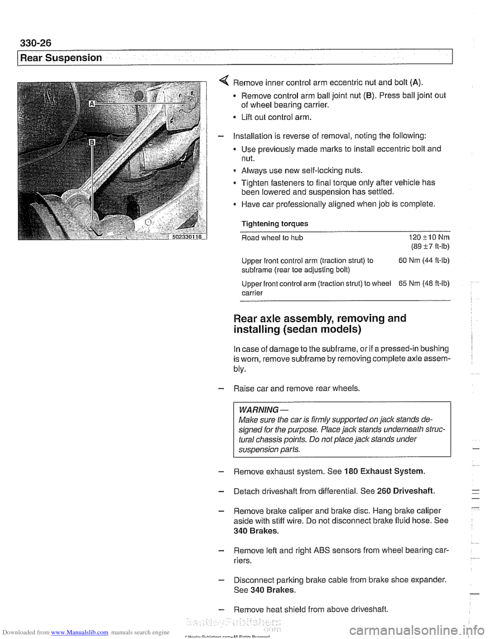
Remove inner control arm eccentric nut and bolt (A)
Remove control arm ball joint nut (6). Press ball joint out
of wheel bearing carrier.
Lifl out control arm.
Installation is reverse of removal, noting the following:
Use previously made
marks to install eccentric bolt and
nut.
Always use new self-locking nuts.
Tighten fasteners to final torque only after vehicle has
been lowered and suspension has settled.
0 Have car professionally aligned when job is complete.
Tightening
torques
Road wheel to hub 120klONm
(89 i7 ft-lb)
Upper front control arm (traction strut) to 60
Nm (44
ft-lb)
subframe (rear toe adjusting bolt)
Upper front control arm (traction strut) to wheel
65 Nm (48 ft-lb)
carrier
Rear axle assembly, removing and
installing (sedan models)
In case of damage to the subframe, or if a pressed-in bushing
is worn, remove
subframe by removing complete axle assem-
bly.
- Raise car and remove rear wheels.
WARNING-
Make sure the car is firmly supported on jack stands de-
signed for the purpose. Place jack stands underneath struc-
tural chassis points. Do not place
jack stands under
suspension parts.
- Remove exhaust system. See 180 Exhaust System
- Detach driveshaft from differential. See 260 Driveshaft.
- Remove brake caliper and brake disc. Hang brake caliper
aside with stiff wire. Do not disconnect brake fluid hose. See
340 Brakes.
- Remove lefl and right ABS sensors from wheel bearing car-
riers.
- Disconnect parking brake cable from brake shoe expander.
See 340 Brakes.
- Remove heat shield from above driveshaft.
Page 725 of 1002
Downloaded from www.Manualslib.com manuals search engine
Rear Suspension
- Remove exhaust system. See 180 Exhaust System.
- Detach driveshaft from differential. See 260 Driveshaft.
- Remove brake caliper and brake disc. Hang brake caliper
aside with stiff wire. Do not disconnect brake fluid hose. See
340 Brakes.
- Remove left and right ABS sensors from wheel bearing car-
riers.
Disconnect parking brake cable from brake shoe expander.
See 340 Brakes.
Remove heat shield from above driveshaft
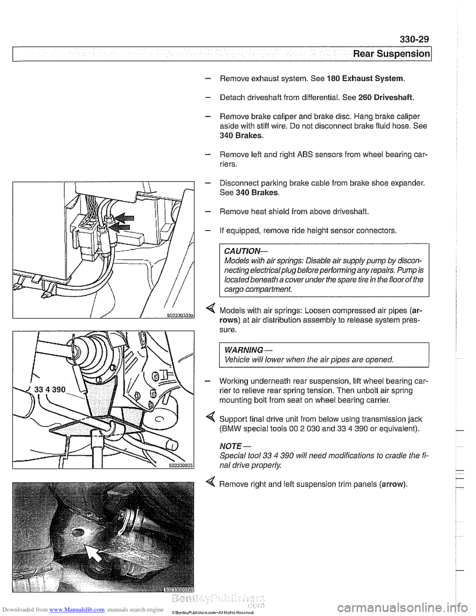
If equipped, remove ride height sensor connectors
CAUTION-
Models with air springs: Disable air supply pump by discon-
necting electrical plug before performing any repairs. Pump is
locatedbeneath a coverunder
thespare tire in the floorof the
carqo compartment.
Models with air springs: Loosen compressed air pipes (ar-
rows) at air distribution assembly to release system pres-
sure.
WARNING -
Vehicle will lower when the air pipes are opened. 1
- Working underneath rear suspension, lift wheel bearing car-
rier to relieve rear spring tension. Then unbolt air spring
mounting bolt from seat on wheel bearing carrier.
4 Support final drive unit from below using transmission jack
(BMW special tools 00 2 030 and 33 4 390 or equivalent).
NOTE-
Special tool 33 4 390 will need modifications to cradle the fi-
nal drive properly
4 Remove right and left suspension trim panels (arrow),
Page 787 of 1002
Downloaded from www.Manualslib.com manuals search engine
340-25
Brakes
- Remove complete exhaust system as described in 180 Ex-
haust System.
- Remove center tunnel heat shield.
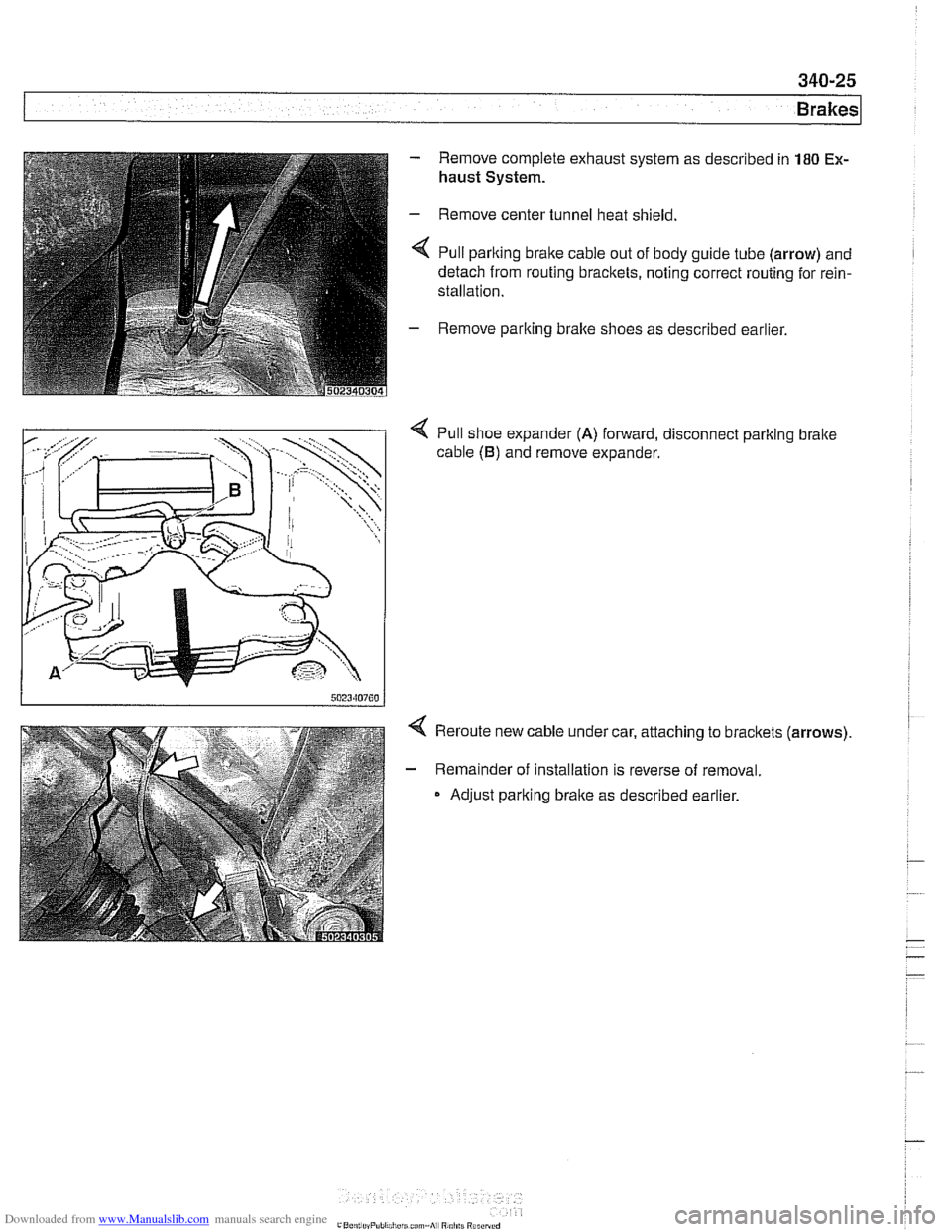
< Pull parlting brake cable out of body guide tube (arrow) and
detach from routing bracltets, noting correct routing for rein-
stallation.
- Remove parlting bralte shoes as described earlier.
4 Pull shoe expander (A) forward, disconnect parlting bralte
cable
(B) and remove expander.
4 Reroute new cable under car, attaching to bracltets (arrows).
- Remainder of installation is reverse of removal.
Adjust parking brake as described earlier.
Page 997 of 1002
Downloaded from www.Manualslib.com manuals search engine
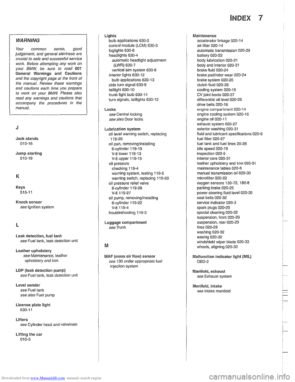
INDEX 7
WARNING
Your common sense, good
judgement, and general alertness are
crucial to safe and successful service
work. Before
attempting any work on
your BMW, be sure to read 001
General Warnings and Cautions
and the copyright page at the front of
the manual. Review these warnings
and cautions each time you prepare
to
work on your BMW. Please also
read any warnings and
caulions that
accompany
/he procedures in the
manual.
Jack stands
010-16
Jump starting 010-19
Keys
515-1 1
Knock sensor
see Ignition system
Leak detection,
fuel tanlr
see Fuel tank, leak detection unit
Leather upholstery
see Maintenance, leather
upholstery and trim
LDP
(leak detection pump)
see Fuel
tanir, leal( detection unit
Level sender
see Fuel tank
see also Fuel pump
License
plate iight
630-1 1
Lifters see Cylinder head and vaivetrain
Lifting the car
010-5 Lights
bulb applications
630-2
control module (LCM) 630-3
foglights 630-8 headiighls 630-4
automatic headlight adjustment
(LWR)
630-7
vertical aim system 630-8 interior lights 630-12
bulb applications 630-13
side turn signal 630-9
taillight 630.10 trunk light bulb 630-14
turn signals, taillights 630-12
LOClCS see Central loci(ing
see also Door loclrs
Lubrication system
oil
level warning switch, replacing
119-20
oil pan, removinglinstalling
6-cylinder 119-10
V-E lower 119-13 V-8 upper 119-15
oil pressure
checiring 11
9-4
warning system, testing 119-5 warning switch, replacing 119-20
oil pressure
reliel valve
6-cylinder 119-26
V-8 11 9-27
oil pump, removinglinstalling
6-cylinder
119-22
V-8 1 19-4
troubieshooting 119-3
Luggage compartment
seeTrunk
MAF (mass air flow) sensor
see 130 under appropriate fuel
injection system Maintenance
accelerator linkage
020-14 air filter 020-14
automatic transmission 020-29
battery 020-22
body lubrication 020-31 body and interior 020-31
braire fluid 020-24
brake padlrotor wear 020-24
brake system 020-25 clutch fluid 020-26
cooling system 020-15
CV ioint boots 020-27
differential oil level 020-26
drive bells 020-16 engine comparlmenl 020-14
engine cooling system 020-16
engine oil 020-1 1 exhaust system 020-27
exterior washing 020-31
fluid and lubricant specifications 020-9
fuel lilter 020-27 fuel lanir and fuel lines 20-28
idle speed 020-19
inspection 020-5
interior care 020-31
lealher upholslery and trim 020-31
maintenance tables 020-6
manual transmission oil 020-30
microiilter 020-22 oxygen sensors 130-72, 180-8
parlcing brake 020-25
power steering fluid level 020-20
seat belts
020-32 service indicator 020-3
spark plugs 020-20
special cleaning 020-32 suspension, front 020-29
suspension, rear 020-29
tires 020-29
washing
020-32
waxing 020-32 windshield wiper blade 020-33
wheels, aligning 020-30
Malfunction indicator iight (MIL)
OED-2
Manifold, exhaust
see Exhaust system
Manifold,
intake
see Intake maniiold
Page 1002 of 1002
Downloaded from www.Manualslib.com manuals search engine
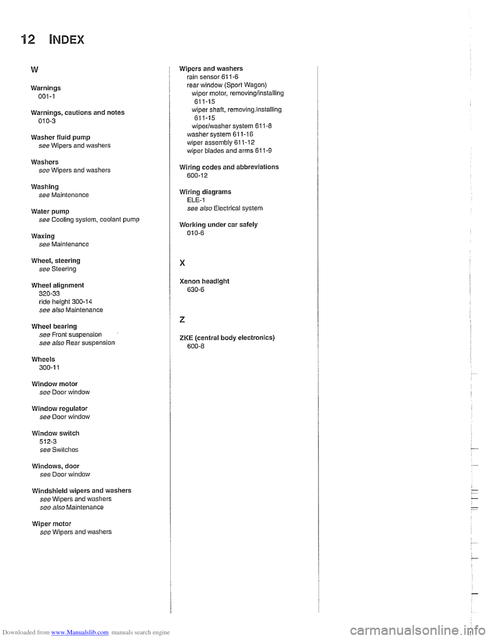
112 INDEX
Warnings 001-1
Warnings, cautions and notes
01
0-3
Washer fluid pump
see Wipers and washers
Washers see Wipers and washers
Washing see Maintenance
Water pump
see Cooling system, coolant
pump
Waxing
see Mainienance
Wheel, steering
see Steering
Wheel alignment
320-33 ride [height 300-14
see also Maintenance
Wheel bearing
see Front suspension
see also Rear suspension
Wheels
300-1 1
Window motor see Door window
Window regulator
see Door window
Window switch
512-3
see Switches
Windows, door
see Door window
Windshield wipers and washers
see Wipers and washers
see also Maintenance
Wiper motor
see Wipers and washers Wipers and
washers
rain sensor 61
1-6 rear window (Sport Wagon) wiper motor, removingiinstaiiing
611-15 wiper shaft, removing.instaiiing
611-15
wiperiwasher system 61
1-8 washer system 611-16
wiper
assembly 611-12
wiper blades and arms 61 1-9
Wiring codes and abbreviations
600-12
Wirinq diaarams ELF-I -
see also Electrical system
Working under car safely
010-6
Xenon headlght
630-6
ZKE (central body electronics)
600-8