Abs brake switch BMW 528i 2000 E39 Workshop Manual
[x] Cancel search | Manufacturer: BMW, Model Year: 2000, Model line: 528i, Model: BMW 528i 2000 E39Pages: 1002
Page 7 of 1002
Downloaded from www.Manualslib.com manuals search engine
001 General Warnings and Cautions
PLEASE READ THESE WARNINGS AND CAUTIONS
BEFORE PROCEEDING
WITH MAINTENANCE AND REPAIR WORK.
WARNINGS-
See also CAUTIONS
- Some repairs may be beyond your capability. If you lack the skills, - Catch draining fuel, oil, or brake fluid in suitable containers. Do
tools and equipment, or a suitable workplace for any procedure
not use
foodor beverage containers that might mislead someone
described in this manual, we suggest you leave such repairs to
into
drinking from them. Store flammable fluids away from fire
an authorized BMW dealer service department or other qualified
hazards. Wipe up spills at once, but do not store the oily rags,
shop. which can ignite and burn spontaneously.
. Do not reuse any fasteners that are worn or deformed. Many fas- Always observe good worRshop practices. Wear qoqqles when
teners are designed to be used only once and become
unreliable you operate machine tools or work with battery acid:kloves or
and mav fail when used a second time. This includes, but is not other
~rotective clothino should be worn whenever the iob re-
limited io, nuts, bolts, washers, self-locking nuts or bolts, clrclips yires' working with harmful substances.
and cotter pins. Always replace these fasteners with new parts.
Greases, lubricants and other automotive chemicals contain toxic
. Never work under a lifted car unless it is solidly supported on
substances, many of which are absorbed directly through the
stands
desiqned for the purpose. Do not supeort a car on cinder
skin. Read the manufacturer's instructions and warninos careful-
blochs, hollow tiles orotherbrops that may drurnbie undercontin-
uous toad. Never work under a car that is supported solely by a
iack. Never work under the car
while the enqine is runninq. - -
If you aregoing to work underacaron the ground, makesure that
the ground is level. Block the wheels to
keep the car from rolling.
Disconnect the battery negative
(-) terminal to prevent others
from starting the car while you are under it.
- Never run the engine unless the work area is well ventilated. Car-
bon monoxide kills.
Rings, bracelets and other jewelry should be removed so that
they cannot cause electrical shorts, get caught in running ma-
chinery, or be crushed by heavy parts.
- Tie long hair behind your head. Do not wear a necktie, a scarf.
loose clothing, or a necklace when you work near machine tools
or running engines. if your hair, clothing, or jewelry were to get
caught in the machinery, severe injury could result.
DO not attempt to
work on your car if you do not feel well. You in-
crease the
danger of injuryto yourseliand others if you are tired,
uDset or have taken medication or anv other substance that mav
keep you from being fully alert.
Illuminate your work area adequately but safely. Use a portable
iy. Use hand and eye protection. Avoid direct skin conGct.
Disconnect the battery negative (-) terminal whenever you work
on the fuel system
orthe electrical system. Do not smokeorwork
near heaters or other fire hazards. Keep an approved fire extin-
guisher handy.
. Friction materials (such as brake pads or shoes or clutch discs)
contain asbestos fibers or other friction materials. Do not create
dust by grinding, sanding, or by cleaning with compressed air.
Avoid breathing dust. Breathing any
friclion material dust can
lead to serious diseases and may result in death.
Batteries
giveoff explosive hydrogen gas during charging. Keep
sparks, lighted matches and open flame away from the top of the
battery. If hydrogen gas escaping from the cap vents is ignited, it
will ignite gas trapped in the cells and cause the battery to ex-
plode.
Connect and disconnect battery cables, jumper cables or a bat-
tery charger only wilh the ignition switched off. Do not disconnect
the battery while the engine is running.
Do not quick-charge the battery (for boost starting) for longer
than one minute. Wait at least one minute before boosting the
battery a second time.
. . safety lighiforworking lnsideor under the car. Make sure the bulb - Do not allow battery charging vollage to exceed 16.5 volts. If the
is enclosed bv a wire caoe. The hot filament of an accidentallv
batten! beoins ~roducina oas or boilino violentiv, reduce the
broken bulb can ignite spilled
fuel, vapors or oil. , - - - charglng rate. ~oostlng a sutfaled battery at a igh charging rate
can cause an
explosion.
-
Continued on next page
Page 8 of 1002
Downloaded from www.Manualslib.com manuals search engine
I General Warnings and Cautions
WARNINGS (continued)
. The air conditioning system is filled with chemical refrigerant,
which is hazardous. The AIC system should be serviced only by
trained technicians using approved refrigerant recoverylrecycling
equipment, trained in related safety precautions, and familiar with
regulations governing the discharging and disposal of automotive
chemical refrigerants.
. Do not expose any part of the AIC system to high temperatures
such as open flame. Excessive heat will increase system pres-
sure and may cause the system to burst.
Some aerosol tire inflators are highly flammable. Be extremely
cautious when repairing a tire that may have been inflated using
an aerosol tire inflator. Keep sparks, open flame or other sources
of ignition away
from the tire repair area. Inflate and deflate the
tire at least four
times before breaking the bead from the rim.
Completely remove the tire from the rim before attempting any re-
pair.
Cars covered by this manual are equipped with a supplemental
restraint system (SRS), that automatically deploys
airbags and
pyrotechnic seat belt tensioners
In the event oi a frontal or side
impact. These are explosive devices. Handled improperly or with-
out adequate safeguards, they can be accidently activated and
cause serious injury.
- The ignition system produces high voltages that can be fatal.
Avoid contact with exposed terminals and use extreme care when
working on a car with the engine running or the ignition switched
on.
. Place jack stands only at locations specified by the manufacturer.
The vehicle
illtino iack su~olied with the vehicle is intended fortire -. , . changes only. A heavy duty floor jack should be used lo lift vehicle
before installing
jacl( stands. See 010 General.
- Battery acid (electrolyte) can cause severe burns. Flush contact
area
with water, seek medical attention.
Aerosol cleaners and solvents may contain hazardous or deadly
vapors and are highly flammable. Use only in a well ventilated ar-
ea. Do not use on hot surfaces (engines, brakes, etc.).
Do not remove
coolant reservoir or radiator cap with the engine
hot. Danger of burns and engine damage.
CAUTIONS-
See also WARNINGS
- if you lack the slqills, tools and equipment, or a suitable worl(shop
for any procedure described in this manual, leave such repairs to
an authorized BMW dealer or other qualified shop.
BMW is constantly improving its cars and sometimes these
changes, both in parts and specifications, are made applicable to
earlier models. Therefore, part numbers listed in this manual are
for reference only. Always check with your authorized BMW deal-
er parts department for the latest information.
Before starting a job, make certain that you have all the neces-
sary tools and parts on hand. Read ail the instructions thorough-
ly, and do not attempt shortcuts. Use tools appropriate to the
work and use only replacement parts meeting BMW specifica-
tions.
Use pneumatic and electric tools only to loosen threaded parts
and fasteners. Never use these tools to tighten fasteners, espe-
cially on light alloy parts. Always use a torque wrench to tighten
fasteners to the tightening torque specification listed.
Be mindful of the environment and ecology. Before you drain the
crankcase, find out the proper way to dispose of the
oil. Do not
pour
oil onto the ground, down a drain, or into a stream, pond or
lake. Dispose of waste in accordance with Federal, State and
Local laws.
The control module for the anti-lock brake system
(ABS) cannot
withstand temperatures from a paint-drying booth or a heat
lamp
in excess of 203" F (95°C) and should not be subjected to tem-
peratures in excess of 185°F
(8S°C) for more than two hours.
- Before doing any electrical welding on cars equipped with ABS,
disconnect the battery negative
(-) terminal (ground strap) and
the ABS control module connector.
- Always make sure ignition is off before disconnecting battery.
Label battery cables before disconnecting. On some models, bat-
tery cables are not color coded.
Disconnecting the battery may erase fault code@) stored in control
module memory. Using special BMW diagnoslic equipment, check
lor
iauit codes prior to disconnecting the battery cables. If the mal-
I.mct on ndicator Ignt (MIL) s I. ..minaled. see OBD On-Board
Diaanostics
Tl11s iant is iuenlfted as lne Check Ena~ne oht
(1997-2000 models jor~ervlce Engine Soon light (2061 andlater
models). If any other system iaults have been detected (indicated
by an illuminated warning light), see an authorized BMW dealer.
If a normal
or rapid charger is used to charge battery, the battery
must be disconnected and removed from the vehicle in order to
avoid damaging the vehicle.
- Do not quick-charge the battery (for boost starting) for longer
than one minute. Wait at least one minute before boosting the
battery a second time.
* Connect and disconnect a battery charger only with the battery
charger switched off.
- Sealed or "maintenance free" batteries should be slow-charged
only, at an amperage rate that is approximately 10% of the bat-
tery's ampere-hour (Ah)
rating.
. Do not allow battery charging voltage to exceed 16.5 volts. If the
battery begins producing gas or boiling violently, reduce the
charging rate.
Boosting a sulfated battery at a high charging rate
can cause an explosion.
Page 454 of 1002
Downloaded from www.Manualslib.com manuals search engine
-
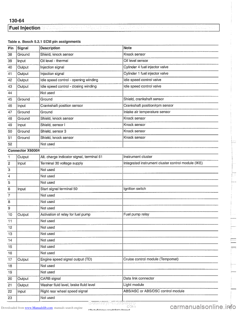
Fuel Injection
Table e. Bosch 5.2.1 ECM pin assignments
Pin
I~iqnal 1 Description 1 Note
I I I
46 llnput ICrankshaft position sensor Icrankshaft positionlrpm sensor
38
39
40
41
42
43
44
45 Ground Input
Output
Output
Output
Output
Ground
47
48
49
50
51
Not used
I Not used
52
Shield, knock sensor
Oil level
- thermal
Injection signal
injection signal
Idle speed control - opening winding
Idle speed control - closing winding
Not used
Ground
Ground
-- Ground Input
Ground
Ground Not used Knock sensor
Oil level sensor
Cylinder
4 fuel injector
valve
Cylinder
1 fuel injector valve
Idle speed control valve
Idle speed control valve
Shield, crankshaft sensor
5
6
7
12 Not used
Ground
Intake air temperature sensor
Connector
X60004
8
9 10
11
14 1 1 Not used I
Shield, knock sensor
Shield, sensor
I
Shield, sensor 3
Shield, itnock sensor
Input
- Knoclc sensor
Knock sensor
Knock sensor
Knock sensor
Instrument cluster
Output
2 llnput l~erminal 30 voltage supply /Megrated instrument cluster control module (IKE)
Alt. charge indicator signal, terminal 61 1
Not used
Start signal terminal
50
Not used
15
16
17
18
Output
Ignition switch
Not used
Not used
Activation of relay for fuel pump
Not used
19
Fuel pump relay
Output Not used
I I I 20 loutput ICARB signal /Data link connector
Not
used
Not used
Engine speed signal output (TD)
Not used
Light module
21
Cruise control module (Tempomat)
22 llnput I Right rear wheel speed signal /ABS/ASC or ABSIDSC control module
Oulput
Washer
fluid level,
brake fluid level
Page 469 of 1002
Downloaded from www.Manualslib.com manuals search engine
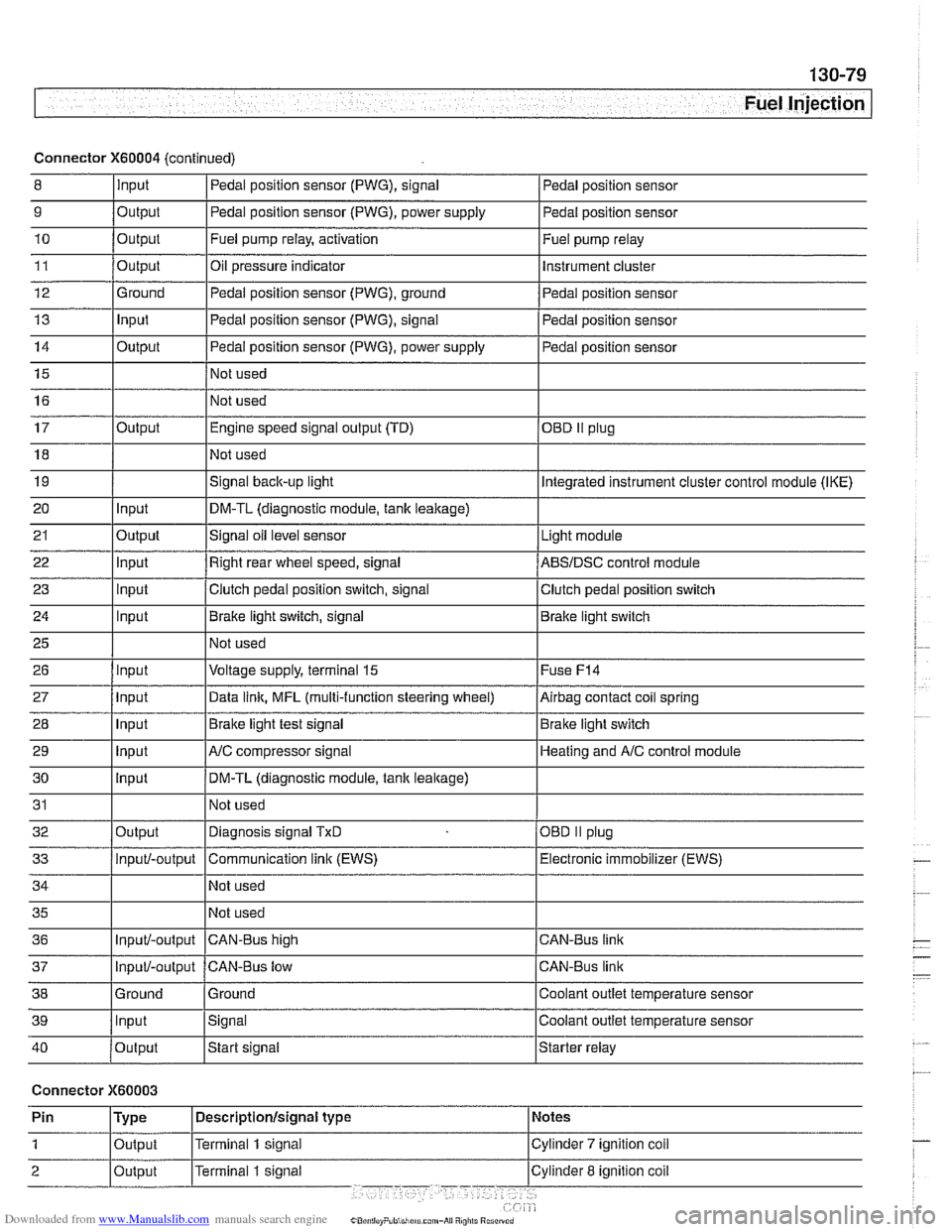
Fuel Injection I
Connector X60004 (continued)
8 10
11
12
13
14
15
16
9
Output 0
Input
17
18
19
20
21
22
23
24
25
26
27
28
29
30
31
32
33
34
35
36
39
llnput lsignal l~oolant outlet temperature sensor
Output
Output
Ground
Input
Output
I I - I
40 /output Istart signal Istarter relay
Pedal position sensor (PWG), signal
Output Input
Output
input
Input
Input
Input
Input
Input
input
Input
Output
Input/-output
Input/-output
37
Connector X60003
Pedal position sensor
Fuel pump relay, activation
Oil pressure indicator Pedal position sensor (PWG), ground
Pedal position sensor (PWG), signal
Pedal position sensor (PWG), power supply
Not used
Not used Fuel
pump relay
Instrument cluster
Pedal position sensor
Pedal position sensor
Pedal position sensor
Engine speed signal output (TD)
Not used
Signal
back-up light
DM-TL (diagnostic module,
tank leakage)
Signal oil level sensor
Right rear wheel speed, signal
Clutch pedal position switch, signal
Brake light switch, signal
Not used
Voltage supply, terminal
15
Data link, MFL (multi-function steering wheel)
Brake light test signal
AJC compressor signal
DM-TL (diagnostic module, tank
leakage)
Not used
Diagnosis signal
TxD
Communication link (EWS)
Not used
Not used
CAN-BUS hiqh
38 1 Ground l~round I Coolant outlet temperature sensor
OED II plug
Integrated instrument cluster control module (IKE)
Light module
ABSIDSC control module
Clutch pedal position switch
Brake light switch
Fuse
F14
Airbag contact coil spring
Brake light switch
Heating and
A/C control module
OBD
II plug
Electronic immobilizer (EWS)
CAN-Bus link
CAN-Bus link
Input/-output CAN-Bus low
Page 633 of 1002
Downloaded from www.Manualslib.com manuals search engine
Suspension, Steering and Brakes - ~enerail
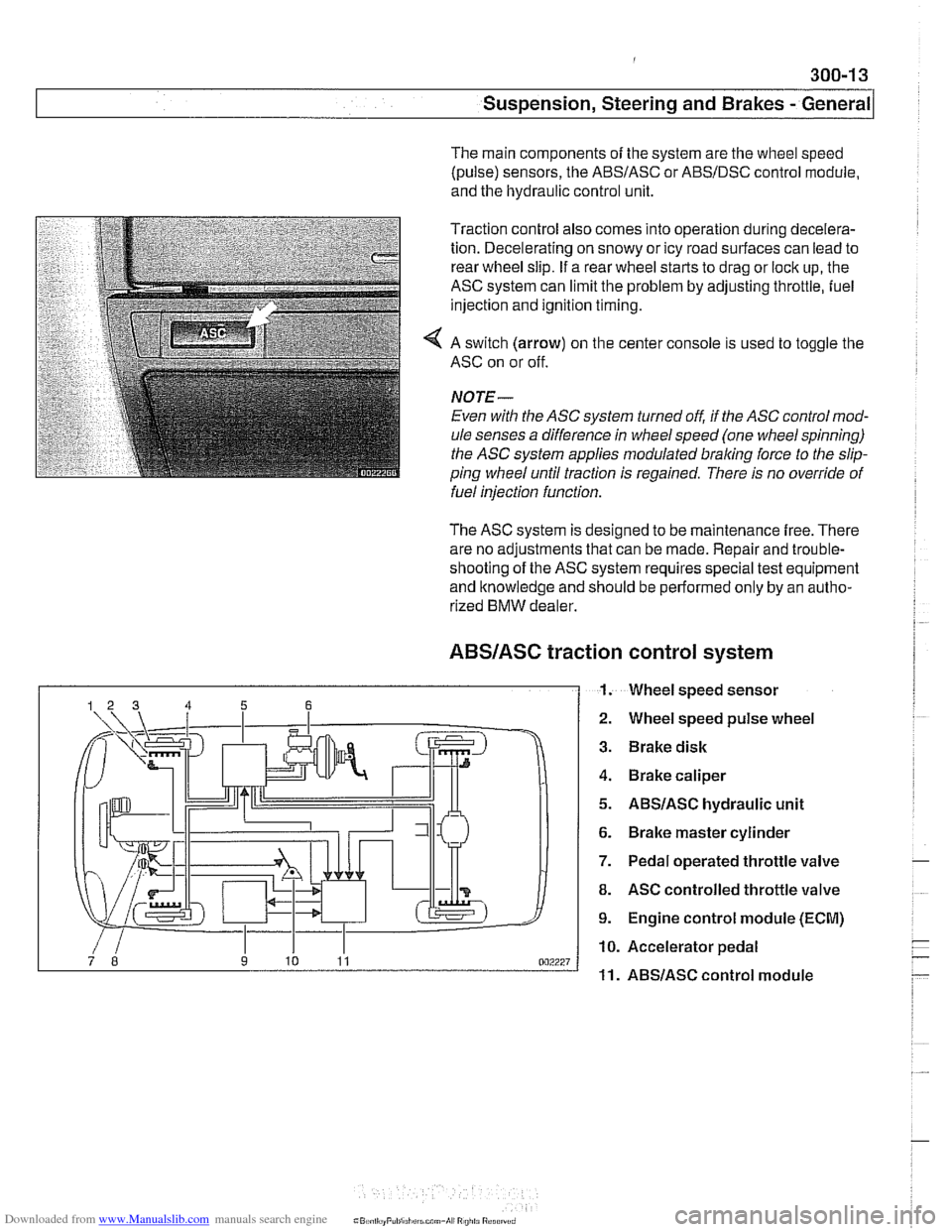
The main components of the system are the wheel speed
(pulse) sensors, the
ABSIASC or ABSIDSC control module,
and the hydraulic control unit.
Traction control also comes into operation during decelera-
tion. Decelerating on snowy or icy road surfaces can lead to
rear wheel slip. If a rear wheel starts to drag or lock up, the
ASC system can limit the problem by adjusting throttle, fuel
injection and ignition timing.
4 A switch (arrow) on the center console is used to toggle the
ASC on or off.
NOJE-
Even with the ASC system turned off, if the ASC control mod-
ule senses a difference in wheel speed (one wheel spinning)
the
ASC system applies modulated braling force to the slip-
ping wheel until traction is regained. There is no override of
fuelinjection function.
The ASC system is designed to be maintenance free. There
are no adjustments that can be made. Repair and trouble-
shooting of the ASC system requires special test equipment
and knowledge and should be performed only by an autho-
rized
BMW dealer.
ABSIASC traction
I 1.
control system
Wheel speed sensor
Wheel speed pulse wheel
Brake disk
Brake caliper
ABSIASC hydraulic unit
Brake master cylinder
Pedal operated throttle valve
ASC controlled throttle valve
Engine control module (ECM)
Accelerator pedal
ABSlASC control module
Page 634 of 1002
Downloaded from www.Manualslib.com manuals search engine
300-1 4
I Susoension. Steerina and Brakes - General
DSC system I
Dynamic Stability Control (DSC)
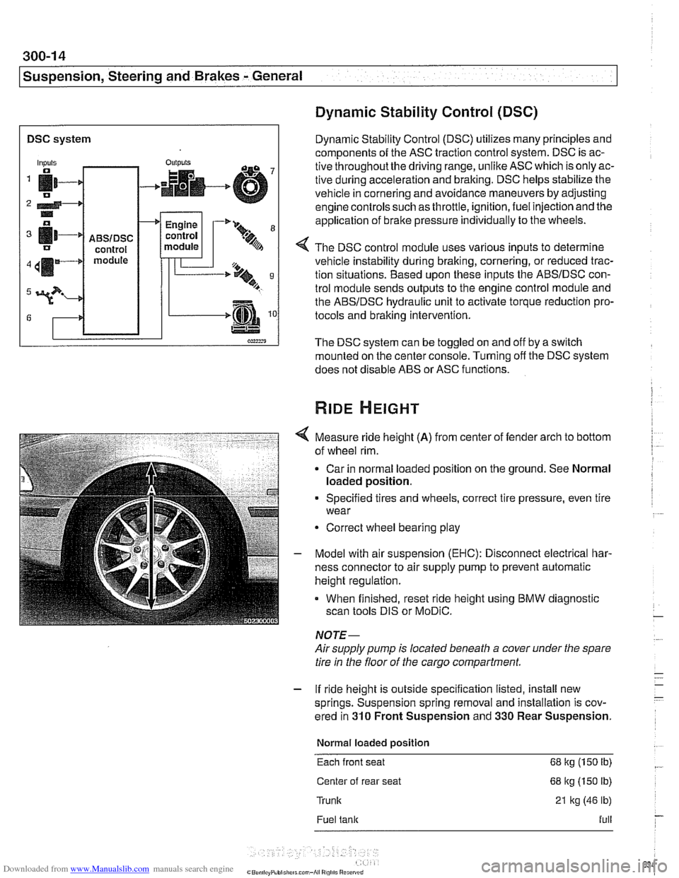
Dynamic Stability Control (DSC) utilizes many principles and
components of the ASC traction control system. DSC is ac-
tive throughoutthe driving range, unlike ASC which is only ac-
tive during acceleration and braking. DSC helps stabilize the
vehicle in cornering and avoidance maneuvers by adjusting
engine controls such as throttle, ignition, fuel injection and the
application of
brake pressure individually to the wheels.
Inputs
fi- 0
2 4-* .. o
[11-' IJ
411m4
3?-
G
4 The DSC control module uses various inputs to determine
vehicle instability during braking, cornering, or reduced trac-
tion situations. Based upon these inputs the ABSIDSC con-
trol module sends outputs to the engine control module and
the ABSIDSC hydraulic unit to activate torque reduction pro-
tocols and braking intervention.
-
ABSIDSC control module
OUI~YIS
4
The DSC system can be toggled on and off by a switch
mounted on the center console. Turning off the DSC system
does not disable ABS or ASC functions.
+
Measure ride height (A) from center of fender arch to bottom
of wheel rim.
Car in normal loaded position on the ground. See Normal
loaded position.
Engine
control
module
Specified tires and wheels, correct tire pressure, even tire
wear
-'* 9-
.%A
Correct wheel bearing play
T'== ..t, 9 B
-.m
Model with air suspension (EHC): Disconnect electrical har-
ness connector to air supply pump to prevent automatic
height regulation.
When finished, reset ride height using BMW diagnostic
scan tools DIS or
MoDiC.
NOTE-
Airsupply pump is located beneath a cover under the spare
tire in the floor of the cargo compartment.
- If ride height is outside specification listed, install new
springs. Suspension spring removal and installation is cov-
ered in
310 Front Suspension and 330 Rear Suspension.
Normal loaded position
Each front seat 68 kg (150 Ib)
Center of rear seat 68 kg (150 lb)
Trunk 21 kg (46 lb)
Fuel tank full
Page 771 of 1002
Downloaded from www.Manualslib.com manuals search engine
Brakes
Brakes, bleeding
The procedure below requires a BMW Service Tester (DIS-
pluslGTl/MoDiC).
- Determine type of traction control (ASC, DSC with precharge
pump, DSC without precharge pump). Be sure to use correct
specification brake fluid, according to application table below.
Brake fluid applications
ABS I ASC and ABS / DSC models DOT 4 brake fluid
with precharge pump (to 911998)
ABS I DSC models without precharge DOT 4 low viscosity
pump (911998 and later) brake
fluid
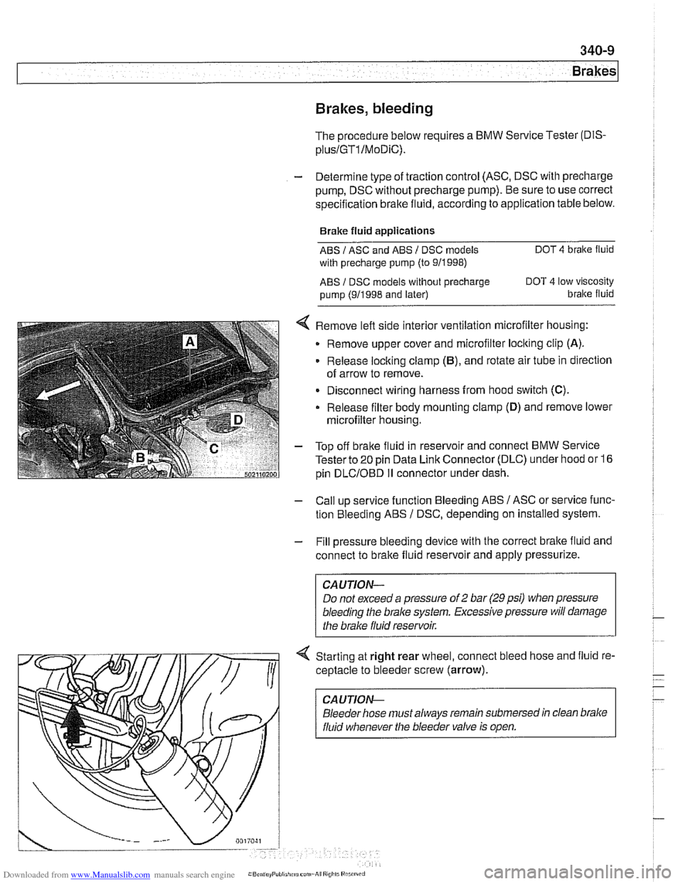
< Remove left side interior ventilation microfilter housing:
Remove upper cover and microfilter loclting clip
(A).
Release locking clamp (B), and rotate air tube in direction
of arrow to remove.
Disconnect wiring harness from hood switch
(C).
Release filter body mounting clamp (D) and remove lower
microfilter housing.
- Top off bralte fluid in reservoir and connect BMW Service
Tester to
20 pin Data Link Connector (DLC) under hood or 16
pin
DLCIOBD I1 connector under dash.
- Call up service function Bleeding ABS / ASC or service func-
tion Bleeding ABS
/ DSC, depending on installed system.
- Fill pressure bleeding device with the correct brake fluid and
connect to brake fluid reservoir and apply pressurize.
Do not exceed a pressure of
2 bar (29 psi) when pressure
bleeding the
brake system. Excessive pressure will damage
4 Starting at right rear wheel, connect bleed hose and fluid re-
ceptacle to bleeder screw (arrow).
CA UTlON-
Bleeder hose must always remain submersed in clean brake
fluid whenever the bleeder valve is open.
Page 788 of 1002
Downloaded from www.Manualslib.com manuals search engine
1 Brakes
ABS COMPONENT REPLACEMENT
CA UTIOW-
If the tires on the car are of different makes, the ABS/trac-
tion controlsystem may overreact. Only fit tires of the same
make and treadpattern.
In adverse conditions, such as trying to rock the car out
of deep snow or other soft surface, or when snow
chains are fitted, it is advisable to switch off traction
control and allow
tlie car driveline to operate conven-
tionally.
All E39 vehicles are equipped with
Antilock Braking System
(ABS). Early production models featured ABS with Automatic
Stability Control (ABS
I ASC). Later models came equipped
with ABS and Dynamic Stability Control (ABS
/ DSC). This
manual will refer to these systems as ABS. ASC or DSC will
be specified when necessary.
For ABS system and component descriptions, see
300 Sus-
pension, Steering and Brakes-General.
Wheel speed sensor, replacing
- Raise applicable end of car.
Make sure that the car is firmly supported on
jack stands de-
signed for the purpose. Place
jack stands beneath structural
chassis points. Do not place jack stands under suspension
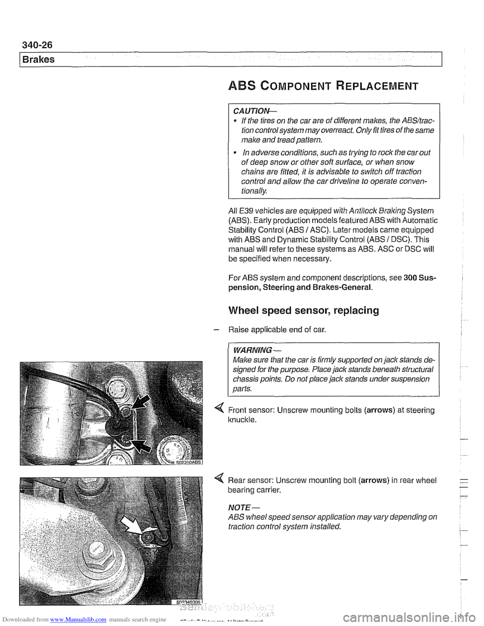
< Front sensor: Unscrew mounting bolts (arrows) at steering
knuckle.
4 Rear sensor: Unscrew mounting bolt (arrows) in rear wheel
bearing carrier.
NOTE-
ABS wheelspeed sensor application may vary depending on
traction control system installed.
Page 792 of 1002
Downloaded from www.Manualslib.com manuals search engine
1 Brakes
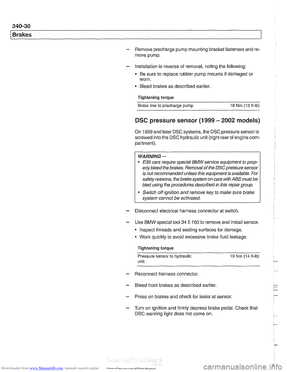
- Remove precharge pump mounting bracket fasteners and re-
move pump.
- Installation is reverse of removal, noting the following:
Be sure to replace rubber pump mounts if damaged
01
worn.
Bleed brakes as described earlier.
Tightening torque Brake line
to precharge pump 18 Nrn (13 ft-lb)
DSC pressure sensor (1 999 - 2002 models)
On 1999 and later DSC systems, the DSC pressure sensor is
screwed into the DSC hydraulic unit (right rear of engine com-
partment).
WARNING-
* €39 cars require special BMW service equipment to prop-
erly bleed the brakes. Removal of the
DSCpressure sensor
is not recommended unless this equipment is available. For
safety reasons, the brake system on cars with ABS must be
bled using the procedures described in this repair group.
Switch off ignition and remove
key to male sure brake
system cannot be activated.
- Disconnect electrical harness connector at switch.
- Use BMW special tool 34 5 160 to remove and install sensor.
Inspect threads and sealing surfaces for damage.
* Work quicltly to avoid excessive brake fluid leakage.
Tightening torque
Pressure sensor
to hydraulic 19 Nrn (14ft-lb)
unit
- Reconnect harness connector
- Bleed front brakes as described earlier.
- Press on brakes and check for leaks at sensor.
- Turn on ignition and firmly depress brake pedal. Check that
DSC warning light does not come on.
Page 991 of 1002
Downloaded from www.Manualslib.com manuals search engine
INDEX 'tl
WARNING
Your common sense, good
judgemenl, and general alertness are
crucial to sale and successiul service
worlr. Belore attempting any work on
your
BMM be sure lo read 001
General Warnings and Cautions
and the
copyriglll page at the front 01
the manual. Review these warnings
and
caulions each lime you prepare
lo work on your BMW. Please also
read any warnings and cautions that
accompany
tile procedures in the
manual.
312-way valve (running losses)
see Fuel tank
Abbreviations, commonly used 600-14
ABS (antilock brake system)
see
Bral(es
A/C air distribution motors
see stepper motors (below)
blower final stage (resistor pack),
replacing
640-16
blower, removinglinslalling
640-1 5
compressor, replacing
640-24 condenser, replacing 64045
control panellmodule, removing1
installing
640-1 1
evaporakr, removinglinstalling 640-29
evaporator temperature sensor
640-12 expansion valve, removinglinstailing
640-27
IHKA/ IHKR system description 640-5
receiveridrier, replacing 640-26
stepper motors 640-1 3 ventilation microiilter, replacing
020-22. 640-17
see also Heating
Accelerator
iinlcage
see Maintenance
Activated carbon canister
see Fuel tank
ADS (auxiliary throttle valve)
130-57
Air compressor
330-44
Air conditioning
see
AIC
Air distribution (flap) motors
seeNC, stepper motors
Air filter see Maintenance
Air spring
300-6, 330-12
Airbag system (SRS)
2-stage
airbag 721-4
control module, replacing 721-7 driver airbag, removinglinstalling
721-8
iiead protection airbag 721-12 components 721-1 1
indicator
lighl721-4
passenger airbag, removinglinstalling
721-9 side-impact airbags crash sensor,
replacing
721-7
Airflow sensor see 130 under appropriate
fuel
injection system
Air pump
see 130 under appropriate fuel
injection system, secondary air
injection system
Air suspension
see Electronic height control
(EHC)
Alarm
see Anti-theft alarm
Alignment see
Wheei alignment
Aluminum suspension components
300-2
Antenna 650-6
Alternator see Battery, starter, alte rnator
Amplifier
650-4
Anti-theft alarm (DWA)
515-24 emergency disarming 515-31
Antifreeze (engine coolant)
see Maintenance
see also Cooling system
Antilock brake system (ABS) see Brakes
ASC see Brakes
ATF (automatic transmission fluid)
see Automatic transmission
see also Cooling systern
Automatic headlight adjustmenl
(LWR) see Lights
Automatic seat belt tensioner
720-4
Automatic shiftloclc
see
Gearshift
Automatic transmission
applications
200-3, 240-4
ATF 020-10, 200-4
capacity 240-8 checking 240-6
drainingifilling 240-7
heat exchanger 170-5
fluid pan and strainer 240-9 gearshift
see Gearshift
ID tag
200-3 range switch 610-6
removaliinstallation 240-10
steptronic see Gearshift
Auxiliary cooling fan
see
Coollng system, electric Ian
Auxiliary throttle valve (ADS)
130-57
Axle joint
see Drive axle
Back-up light switch
automatic transmission see Automatic transmission. range switch
- .~.~~~
manual transmission 230-8 -
- I