Break procedure BMW 528i 2000 E39 Workshop Manual
[x] Cancel search | Manufacturer: BMW, Model Year: 2000, Model line: 528i, Model: BMW 528i 2000 E39Pages: 1002
Page 8 of 1002
Downloaded from www.Manualslib.com manuals search engine
I General Warnings and Cautions
WARNINGS (continued)
. The air conditioning system is filled with chemical refrigerant,
which is hazardous. The AIC system should be serviced only by
trained technicians using approved refrigerant recoverylrecycling
equipment, trained in related safety precautions, and familiar with
regulations governing the discharging and disposal of automotive
chemical refrigerants.
. Do not expose any part of the AIC system to high temperatures
such as open flame. Excessive heat will increase system pres-
sure and may cause the system to burst.
Some aerosol tire inflators are highly flammable. Be extremely
cautious when repairing a tire that may have been inflated using
an aerosol tire inflator. Keep sparks, open flame or other sources
of ignition away
from the tire repair area. Inflate and deflate the
tire at least four
times before breaking the bead from the rim.
Completely remove the tire from the rim before attempting any re-
pair.
Cars covered by this manual are equipped with a supplemental
restraint system (SRS), that automatically deploys
airbags and
pyrotechnic seat belt tensioners
In the event oi a frontal or side
impact. These are explosive devices. Handled improperly or with-
out adequate safeguards, they can be accidently activated and
cause serious injury.
- The ignition system produces high voltages that can be fatal.
Avoid contact with exposed terminals and use extreme care when
working on a car with the engine running or the ignition switched
on.
. Place jack stands only at locations specified by the manufacturer.
The vehicle
illtino iack su~olied with the vehicle is intended fortire -. , . changes only. A heavy duty floor jack should be used lo lift vehicle
before installing
jacl( stands. See 010 General.
- Battery acid (electrolyte) can cause severe burns. Flush contact
area
with water, seek medical attention.
Aerosol cleaners and solvents may contain hazardous or deadly
vapors and are highly flammable. Use only in a well ventilated ar-
ea. Do not use on hot surfaces (engines, brakes, etc.).
Do not remove
coolant reservoir or radiator cap with the engine
hot. Danger of burns and engine damage.
CAUTIONS-
See also WARNINGS
- if you lack the slqills, tools and equipment, or a suitable worl(shop
for any procedure described in this manual, leave such repairs to
an authorized BMW dealer or other qualified shop.
BMW is constantly improving its cars and sometimes these
changes, both in parts and specifications, are made applicable to
earlier models. Therefore, part numbers listed in this manual are
for reference only. Always check with your authorized BMW deal-
er parts department for the latest information.
Before starting a job, make certain that you have all the neces-
sary tools and parts on hand. Read ail the instructions thorough-
ly, and do not attempt shortcuts. Use tools appropriate to the
work and use only replacement parts meeting BMW specifica-
tions.
Use pneumatic and electric tools only to loosen threaded parts
and fasteners. Never use these tools to tighten fasteners, espe-
cially on light alloy parts. Always use a torque wrench to tighten
fasteners to the tightening torque specification listed.
Be mindful of the environment and ecology. Before you drain the
crankcase, find out the proper way to dispose of the
oil. Do not
pour
oil onto the ground, down a drain, or into a stream, pond or
lake. Dispose of waste in accordance with Federal, State and
Local laws.
The control module for the anti-lock brake system
(ABS) cannot
withstand temperatures from a paint-drying booth or a heat
lamp
in excess of 203" F (95°C) and should not be subjected to tem-
peratures in excess of 185°F
(8S°C) for more than two hours.
- Before doing any electrical welding on cars equipped with ABS,
disconnect the battery negative
(-) terminal (ground strap) and
the ABS control module connector.
- Always make sure ignition is off before disconnecting battery.
Label battery cables before disconnecting. On some models, bat-
tery cables are not color coded.
Disconnecting the battery may erase fault code@) stored in control
module memory. Using special BMW diagnoslic equipment, check
lor
iauit codes prior to disconnecting the battery cables. If the mal-
I.mct on ndicator Ignt (MIL) s I. ..minaled. see OBD On-Board
Diaanostics
Tl11s iant is iuenlfted as lne Check Ena~ne oht
(1997-2000 models jor~ervlce Engine Soon light (2061 andlater
models). If any other system iaults have been detected (indicated
by an illuminated warning light), see an authorized BMW dealer.
If a normal
or rapid charger is used to charge battery, the battery
must be disconnected and removed from the vehicle in order to
avoid damaging the vehicle.
- Do not quick-charge the battery (for boost starting) for longer
than one minute. Wait at least one minute before boosting the
battery a second time.
* Connect and disconnect a battery charger only with the battery
charger switched off.
- Sealed or "maintenance free" batteries should be slow-charged
only, at an amperage rate that is approximately 10% of the bat-
tery's ampere-hour (Ah)
rating.
. Do not allow battery charging voltage to exceed 16.5 volts. If the
battery begins producing gas or boiling violently, reduce the
charging rate.
Boosting a sulfated battery at a high charging rate
can cause an explosion.
Page 187 of 1002
Downloaded from www.Manualslib.com manuals search engine
Cylinder Head and Valvetrain
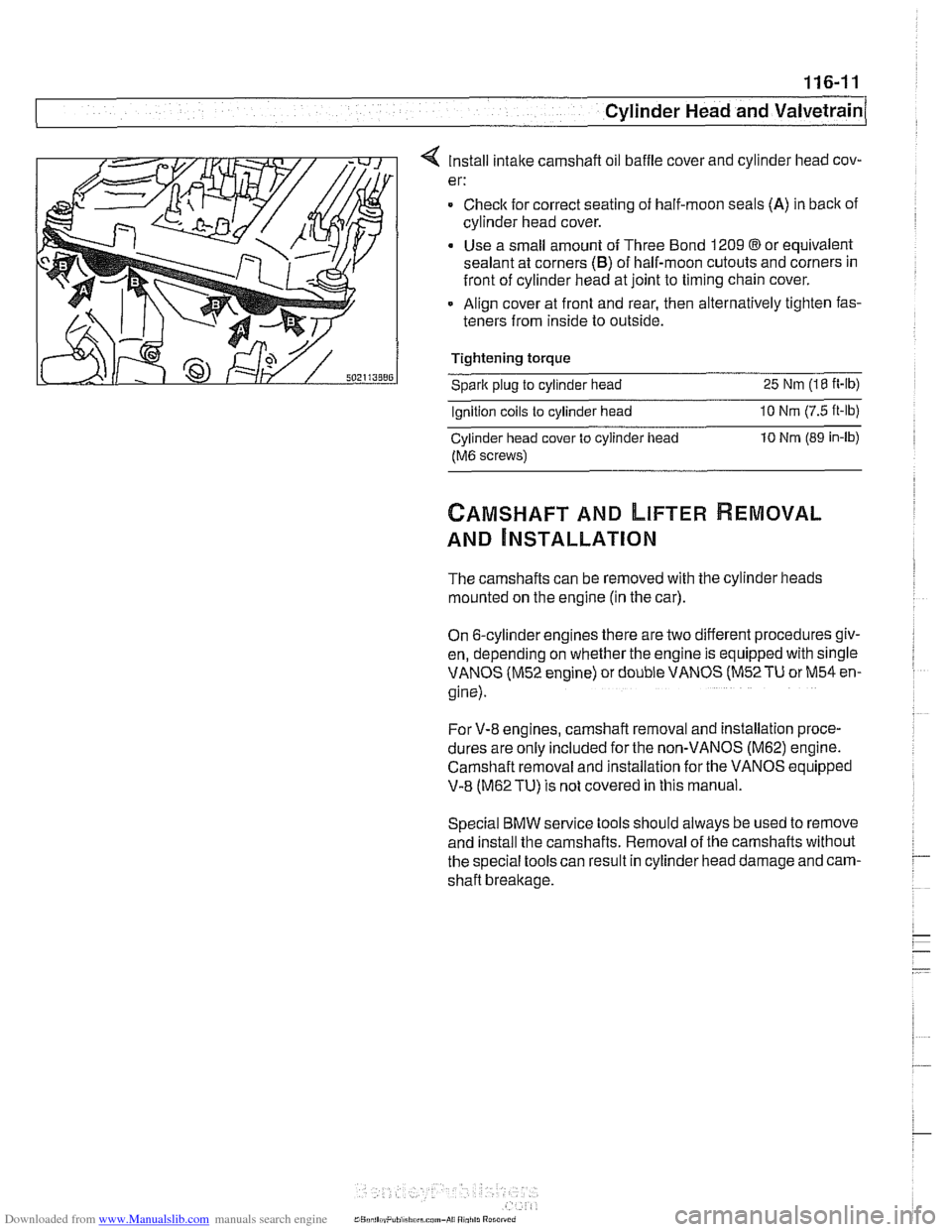
4 Install intake camshaft oil baffle cover and cylinder head cov-
er:
= Checlc for correct seating of half-moon seals (A) in back of
cylinder head cover.
Use a small amount of Three Bond 1209
@or equivalent
sealant at corners
(B) of half-moon cutouts and corners in
front of cylinder head at joint to timing chain cover.
Align cover at front and rear, then alternatively tighten fas-
teners from inside to outside.
Tightening torque
Sparic plug to cylinder head 25 Nm (18 it-lb)
Ignition coils to cylinder head 10 Nrn (7.5 ft-lb)
Cylinder head cover to cylinder iiead 10 Nrn (89 in-lb)
fM6 screws)
CAMSHAFT AND LIFTER REMOVAL
AND ~NSTALLATION
The camshafts can be removed with the cylinder heads
mounted on the engine (in the car).
On 6-cylinder engines there are two different procedures giv-
en, depending on whether the engine is equipped with single
VANOS (M52 engine) or double VANOS
(M52TU or M54 en-
gine).
For V-8 engines, camshaft removal and installation proce-
dures are
only included for the non-VANOS (M62) engine.
Camshaft removal and installation for the
VANOS eq;ipped
V-8 (M62TU) is not covered in this manual.
Special BMW service tools should always be used to remove
and install the camshafts. Removal of the camshafts without
the special tools can result in cylinder head damage and cam-
shaft breakage.
Page 563 of 1002
Downloaded from www.Manualslib.com manuals search engine
Self-adjusting clutch (SAC), breaking in
With normal driving, 800 to 1000 gearshifts are required to
break in the clutch.
Break in the SAC gradually, with light to medium loads, to en-
sure correct operation and long life. Fast sports driving ma-
neuvers may destroy a new
clutch.The following break-in
procedure helps to create the correct coefficient of friction.
Drive normally on level grade. Starting speeds on level
grade may be up to 2000 rpm.
Upshift and downshift through all the gears at 3500
- 4000
rpm.
On medium grades (approx. 12% and up), start
off at ap-
prox. 2500 rpm for the first 5 or so times.
Tightening torques
Clutch slave cylinder to transmission case 22 Nm (16 It-lb)
Clutch master cylinder to pedal cluster 10 Nm (89 in-lb)
Bralte fluid line to clutch master or slave cylinder 17 Nm (13 ft-lb)
Transmission to engine
M8 (Torx) 22 Nm (16 fl-lb)
. M1O (Torx) 43 Nm (32 ft-lb)
MI2 (Torx) 72 Nm (53 it-lb)
Flywheel to crankshaft
6 cylinder engine (use new self-loclting bolts) 105 Nm (77 ft-lb)
V-8 engine 105 Nm (77 ft-lb)
Clutch to flywheel
M8 (8.8 grade)
M8 (10.9 grade) 24
Nm
(18 ft-lb)
34 Nm (25 ft-lb)
Page 758 of 1002
Downloaded from www.Manualslib.com manuals search engine
Final Drive
Drive axles use constant-velocity (CV) joints on both ends.
For replacement parts, only CV joint boots or complete axles
are offered by BMW. The procedure for drive axle removal
varies for sedan and sport wagon. Follow the appropriate pro-
cedure below.
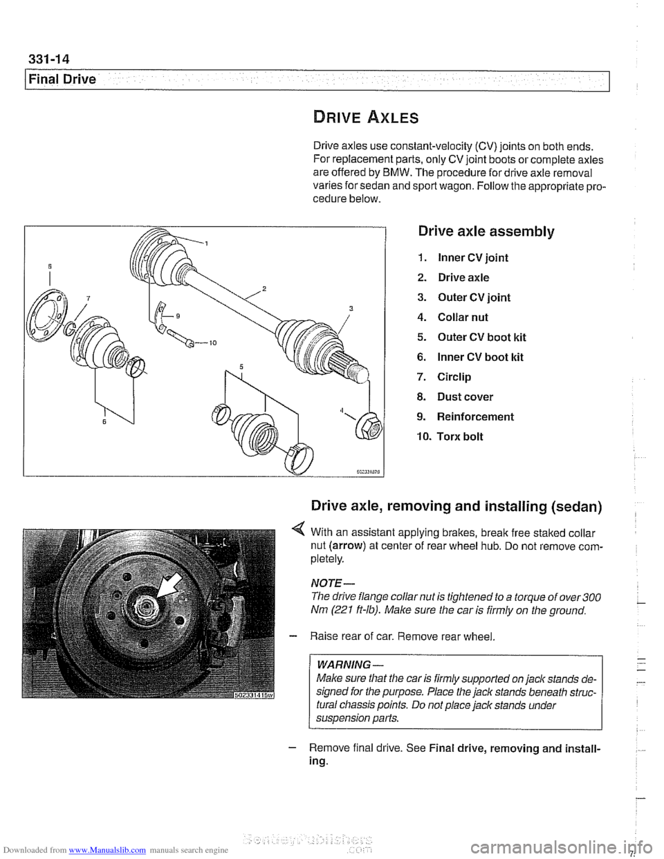
Drive axle assembly
1. lnner CV joint
2. Drive axle
3. Outer CV joint
4. Collar nut
5. Outer CV boot kit
6. lnner CV boot kit
7. Circlip
8. Dust cover
9. Reinforcement
10. Torx bolt
Drive axle, removing and installing (sedan)
4 With an assistant applying brakes, break free staked collar
nut (arrow) at center of rear wheel hub. Do not remove com-
pletely.
NOTE-
The drive flange collar nut is tightened to a torque of over 300
Nm (221 ft-lb). Male sure the car is firmly on the ground.
- Raise rear of car. Remove rear wheel
WARNING -
Make sure that the car is firmly supported on jack stands de-
signed for the purpose. Place the
jack stands beneath struc-
tural chassis points. Do not place jack stands under
suspension parts.
- Remove f~nal drrve. See Final drive, removing and install-
ing.
Page 920 of 1002
Downloaded from www.Manualslib.com manuals search engine
51 5-26
Central Locking and Anti-Theft
Interior sensor UIS (2000 and later models)
The
UIS system uses ultrasonic sound waves instead of elec-
tromagnetic waves. Ultrasonic sound waves are less suscep-
tible to magnetic interference.
Every time the DWA system is armed, the sensor adapts to
whatever objects might be stationary in the interior. The sen-
sor emits ultrasonic waves in a programmed timed cycle. It re-
ceives echoes of the emitted waves. The
UIS amplifies the
received sound wave signals and compares them to the ech-
oes of the transmitted waves. The
UIS also checits the incom-
ing echoes for background hiss (wind noise through a
partially open window) and adapts for this.
If the echoes are consistently similar, no movement is de-
tected.
If the echoes are altered, (inconsistent), the UIS deter-
mines motion in the interior compartment.
If motion is detected, the
UIS changes to a constant cycle
and the echo is compared again.
If the inconsistency is still present the
UIS sends the acti-
vate siren signal to the GM.
Glass breakage sensors
The doorwindows are monitored by inductive sensors mount-
ed on the inside of the door behind the trim panel. A closed
window is recognized by a magnetic plate
on the glass lining
up with the sensor. If the glass is broken, the plate falls away
and the signal from the sensor changes. This causes the GM
to activate the alarm.
Emergency disarming
- An emergency procedure is provided to cancel the DWA in
the event that a fault occurs within the system. The procedure
is as follows:
Driver's door mechanically
unloclted and open within 30
seconds. This will cause triggering of alarm.
All doors closed.
Ignition switch turned to
KL R (ACCESSORY). LED indica-
tor will come on.
- After 10 minutes, alarm is disarmed