Distribution BMW 528i 2000 E39 Workshop Manual
[x] Cancel search | Manufacturer: BMW, Model Year: 2000, Model line: 528i, Model: BMW 528i 2000 E39Pages: 1002
Page 156 of 1002
Downloaded from www.Manualslib.com manuals search engine
. .- --
[Cylinder ~ead Removal and Installation
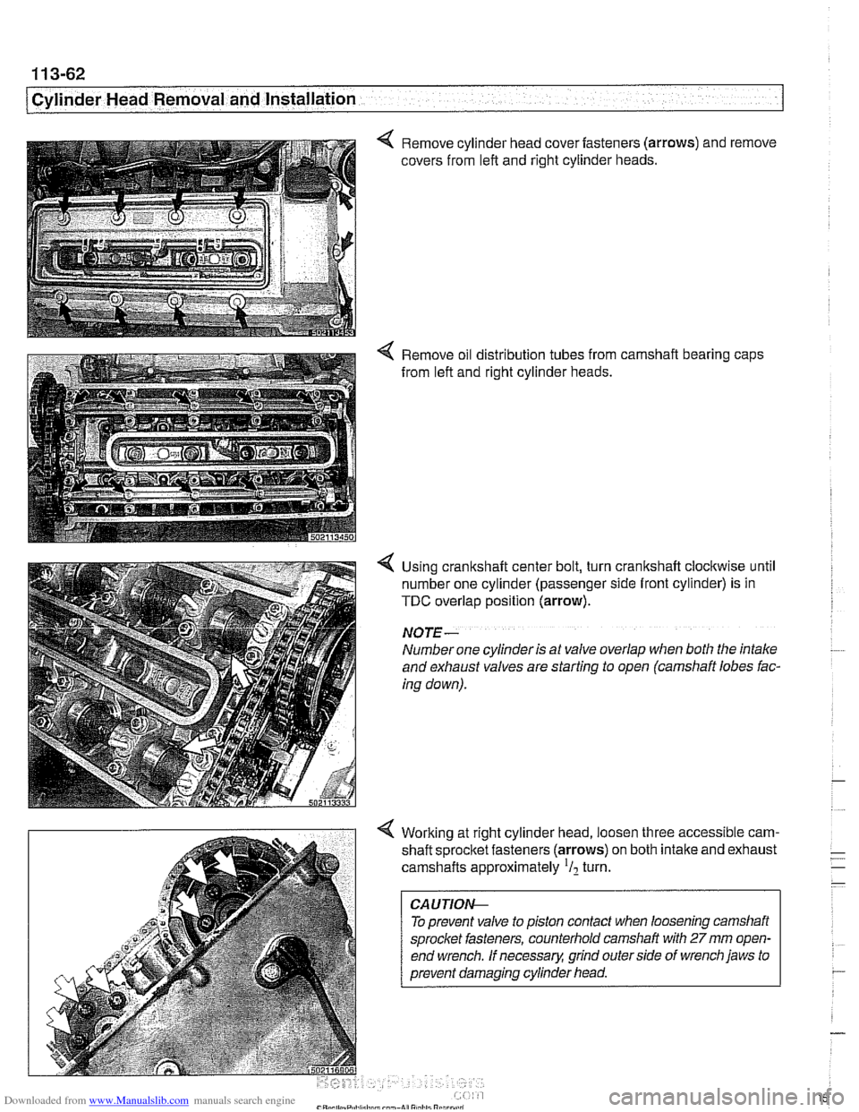
4 Remove cylinder head cover fasteners (arrows) and remove
covers from left and right cylinder heads.
4 Remove oil distribution tubes from camshaft bearing caps
from left and right cylinder heads.
4 Using crankshaft center bolt, turn crankshaft clockwise until
number one cylinder (passenger side front cylinder) is in
TDC overlap position (arrow).
NO JE -
Number one cylinder is at valve overlap when both the intake
and exhaust valves are starting to open (camshaft lobes fac-
ing down).
4 Working at right cylinder head, loosen three accessible cam-
shaft sprocltet fasteners (arrows) on both intake and exhaust
camshafts approximately
'I2 turn.
To prevent valve to piston contact when loosening camshaft
sprocket fasteners, counterhold camshaft with
27 mm open-
end wrench.
If necessary, grind outerside of wrench jaws to
prevent damaging cylinder head.
Page 167 of 1002
Downloaded from www.Manualslib.com manuals search engine
11 3-73
Cylinder Head Removal and Installation /
1
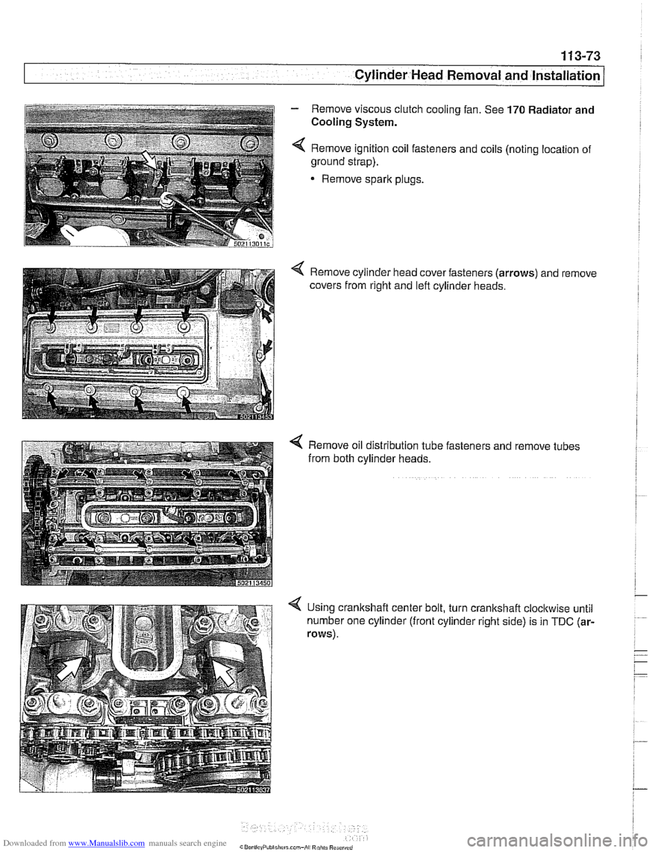
- Remove viscous clutch cooling fan. See 170 Radiator and
i Cooling System. i i I 4 Remove ignition coil fasteners and coils (noting location of
~ ground strap).
1
Remove sparlc plugs.
i
Remove oil distribution tube fasteners and remove tubes
from both cylinder heads.
4 Using crankshaft center bolt, turn crankshaft cloclcwise until
number one cylinder (front cylinder right side) is in
TDC (ar-
rows).
Page 502 of 1002
Downloaded from www.Manualslib.com manuals search engine
.. - -
I Radiator and Cooling System
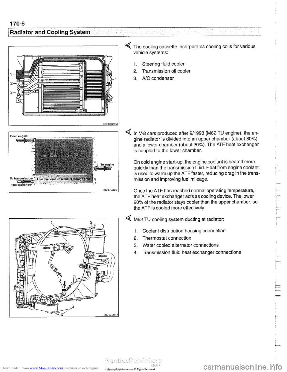
I I 4 The cooling cassette incorporates cooling coils for various
vehicle systems:
1. Steering fluid cooler
2. Transmission oil
coolel
3. AIC condenser
4 In V-8 cars produced after 911998 (M62 TU engine), the en-
gine radiator is divided into an upper chamber (about 80%)
and a lower chamber (about 20%). The ATF heat exchanger
is coupled to the lower chamber.
On cold engine start-up, the engine coolant is heated more
quicltly than the transmission fluid. Heat from engine coolant
is used to warm up the ATF faster, reducing drag in the trans-
mission and improving fuel mileage.
Once the ATF has reached normal operating temperature,
the ATF heat exchanger acts as cooling device. The lower
20% of the radiator
stays cooler than the upper chamber, so
the ATF is cooled more effectively.
4 M62 TU cooling system ducting at radiator:
1. Coolant distribution housing connection
2. Thermostat connection
3. Water cooled alternator connections
4. Transmission fluid heat exchanger connections
Page 712 of 1002
Downloaded from www.Manualslib.com manuals search engine
Rear Suspension Swing arm, removing and installing
(Sport Wagon models)
- Raise rear end of car and remove wheel.
WARNING -
Make sure the car is firmly supported on jack stands de-
signed for the purpose. Place jack stands underneath struc-
tural chassis points. Do not place jack stands under
suspension parts.
CAUJION-
Model with air springs: Disable air supply pump by discon-
necting electricalplug
beforeperforminganyrepairs. Pump is
located beneath a cover under the spare tire in the floor of the
cargo compartment.
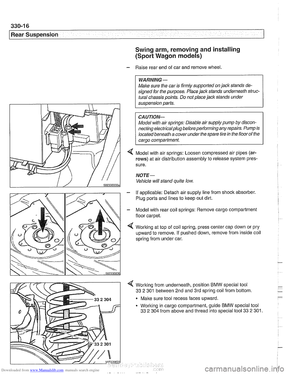
< Model with air springs: Loosen compressed air pipes (ar-
rows) at air distribution assembly to release system pres-
sure.
NOJE-
Vehicle will stand quite low
- If applicable: Detach air supply line from shock absorber.
Plug ports and lines to
lkeep out dirt.
- Model with rear coil springs: Remove cargo compartment
floor carpet.
4 Working at top of coil spring, press center cap down or pry
upward to remove. If pushed down, remove from inside coil
spring from under car.
4 Working from underneath, position BMW special tool
33
2 301 between 2nd and 3rd spring coil from bottom.
Make sure tool recess faces upward.
Working in cargo compartment, guide BMW special tool
33
2 304 from above and thread into special tool 33 2 301.
Page 715 of 1002
Downloaded from www.Manualslib.com manuals search engine
330-1 9
Rear suspension1
Swing arm ball joint, replacing
- Raise rear end of car and remove wheel.
Make sure the car is firmly supported on jack stands de-
signed for the purpose. Place jack stands underneath struc-
tural chassis points. Do not place jack stands under
suspension
parts.
- Sport Wagon model: Support wheel bearing carrier from be-
low.
CA
UTION-
The shock absorberprevents the drive axle and wheel bear-
ing carrier from dropping too far. Supporting the wheel bear-
ing carrier before disconnecting the
shoclc absorber
mounting fastenerprevents damage to the brake hose, park-
ing
brake cable and drive axle CVjoints.
- Model with air shock absorbers: Detach air supply line from
shoclc absorber. Plug ports and lines to keep out dirt.
- Sport Wagon model: Remove shock absorber lower mount-
ing bolt.
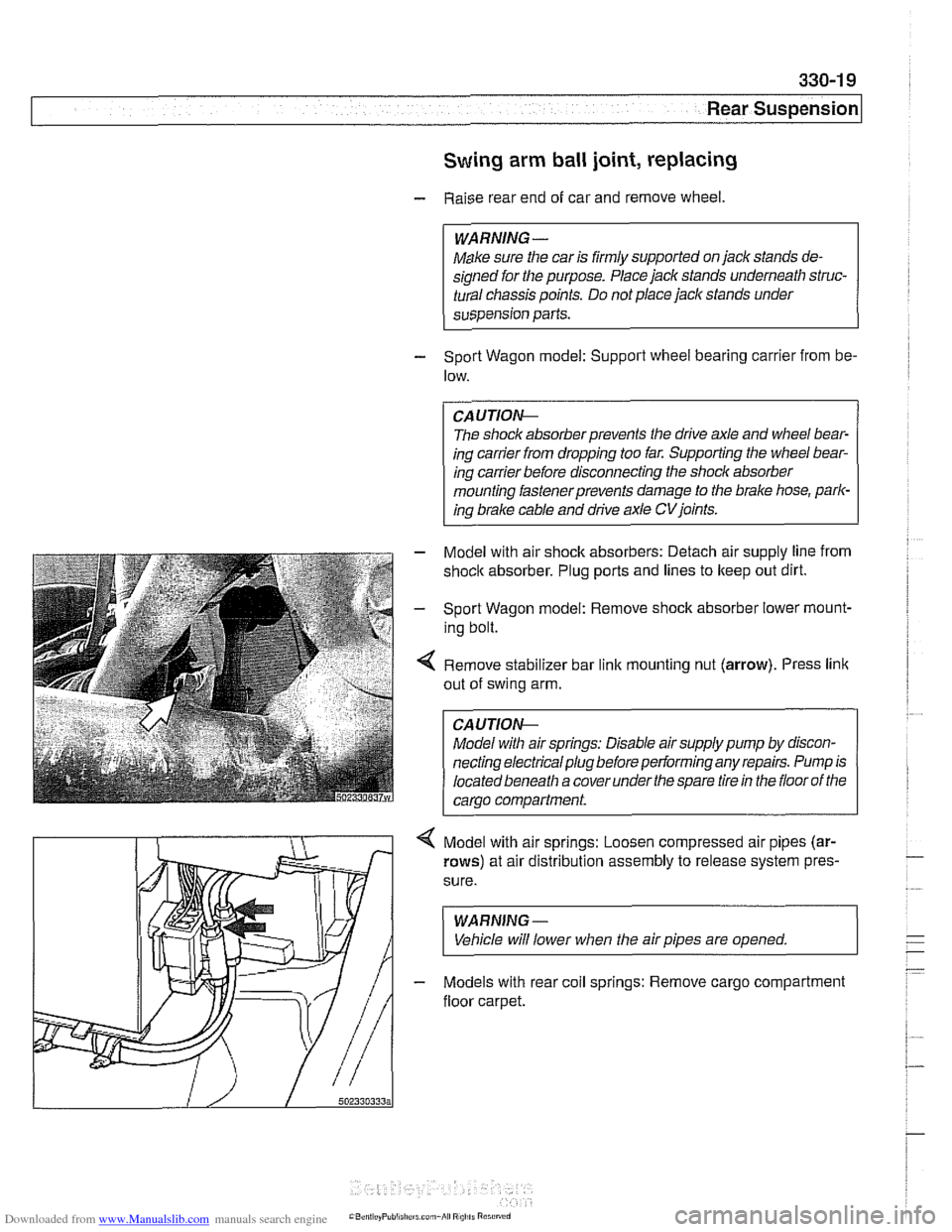
4 Remove stabilizer bar link mounting nut (arrow). Press link
out of swing arm.
Model with air springs: Disable air supply pump by discon-
necting electrical plug before performing any repairs. Pump is
located beneath a cover under
the spare tire in the floor of the
carao
comoartment.
4 Model with air springs: Loosen compressed air pipes (ar-
rows) at air distribution assembly to release system pres.
sure.
WARNING-
Vehicle will lower when the air pipes are opened.
- Models with rear coil springs: Remove cargo compartment
floor carpet.
Page 720 of 1002
Downloaded from www.Manualslib.com manuals search engine
330-24
Rear Suspension
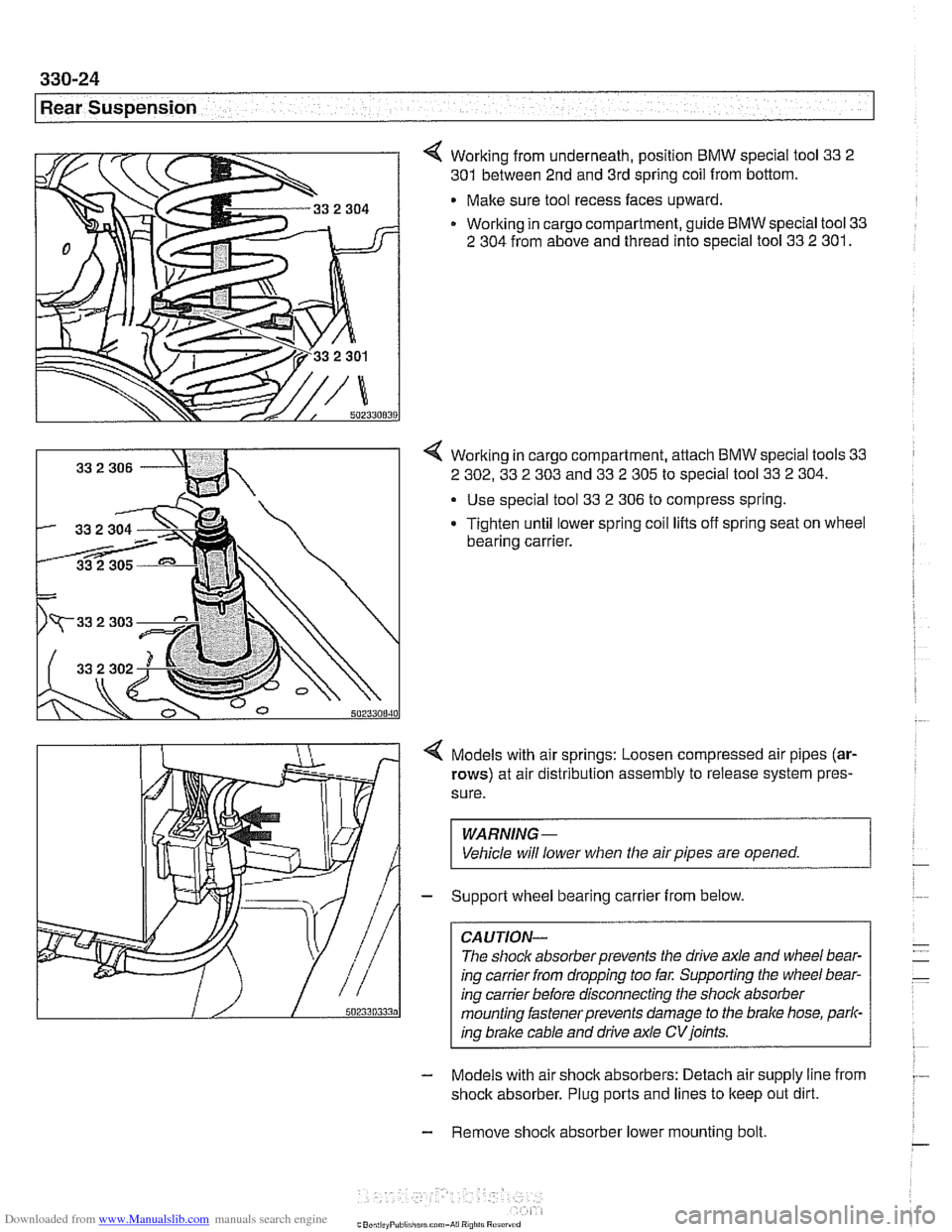
4 Working from underneath, position BMW special tool 33 2
301 between 2nd and 3rd spring coil from bottom.
Make sure tool recess faces upward.
Working in cargo compartment, guide BMW special tool 33
2 304 from above and thread into special tool 33 2 301.
4 Working in cargo compartment, attach BMW special tools 33
2 302, 33 2 303 and 33 2 305 to special tool 33 2 304.
Use special tool 33
2 306 to compress spring.
Tighten until lower spring coil lifts off spring seat on wheel
bearing carrier.
4 Models with air springs: Loosen compressed air pipes (ar-
rows) at air distribution assembly to release system pres-
sure.
WARNING -
Vehicle will lower when the air pipes are opened. 1
- Support wheel bearing carrier from below.
CAUTION-
The shock absorber prevents the drive axle and wheel bear-
ing carrier from dropping too far. Supporting the wheel bear-
ing carrier before disconnecting the shock absorber
mounting iastenerprevents damage to the brake hose,
parl-
ino brake cable and drive axle CV ioints.
- Models with air shock absorbers: Detach air supply line from
shock absorber. Plug ports and lines to keep out dirt.
- Remove shoclc absorber lower mounting bolt
Page 725 of 1002
Downloaded from www.Manualslib.com manuals search engine
Rear Suspension
- Remove exhaust system. See 180 Exhaust System.
- Detach driveshaft from differential. See 260 Driveshaft.
- Remove brake caliper and brake disc. Hang brake caliper
aside with stiff wire. Do not disconnect brake fluid hose. See
340 Brakes.
- Remove left and right ABS sensors from wheel bearing car-
riers.
Disconnect parking brake cable from brake shoe expander.
See 340 Brakes.
Remove heat shield from above driveshaft
If equipped, remove ride height sensor connectors
CAUTION-
Models with air springs: Disable air supply pump by discon-
necting electrical plug before performing any repairs. Pump is
locatedbeneath a coverunder
thespare tire in the floorof the
carqo compartment.
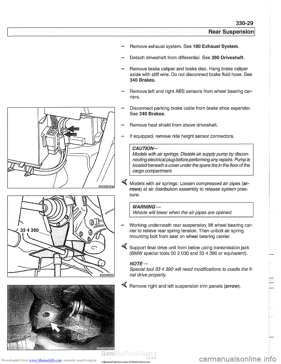
Models with air springs: Loosen compressed air pipes (ar-
rows) at air distribution assembly to release system pres-
sure.
WARNING -
Vehicle will lower when the air pipes are opened. 1
- Working underneath rear suspension, lift wheel bearing car-
rier to relieve rear spring tension. Then unbolt air spring
mounting bolt from seat on wheel bearing carrier.
4 Support final drive unit from below using transmission jack
(BMW special tools 00 2 030 and 33 4 390 or equivalent).
NOTE-
Special tool 33 4 390 will need modifications to cradle the fi-
nal drive properly
4 Remove right and left suspension trim panels (arrow),
Page 731 of 1002
Downloaded from www.Manualslib.com manuals search engine
330-35
Rear Suspension
- Remainder of installation is reverse of removal, noting the fol-
lowing.
Always use new self-loclting nuts.
Make sure all threaded bolts, nuts and mating suriaces are
clean.
Make sure long lower strut bushing fits in hole in wheel
bearing carrier.
Tighten fasteners to final torque only after vehicle has
been lowered and suspension has settled.
Stake axle collar nut after tightening.
Tightening torques
ABS pulse sensor to wheel bearing carrier
8 Nm (6 ft-lb)
Brake rotor to hub 16 Nm (12 ft-lb)
Rear brake pad carrier (caliper) to wheel 65
Nm (48
ft-lb)
bearing carrier
Rear axle shaft to hub
(M27) 300 Nm (221 ft-lb)
Rear strut to wheel bearing carrier 127
Nrn (94 ft-lb)
Road wheel to hub
120+10 Nm
(89
i7 ft-lb)
Swing arm to wheel bearing carrier 256
Nrn (189 ft-lb)
Upper front control arm (traction strut) to 65 Nrn
(48
ft-lb)
wheel carrier
Upper rear control arm to wheel carrier 142
Nrn (105
ft-lb)
Rear wheel bearing carrier, removing and
installing (Sport Wagon models)
- Raise rear end of car and remove wheel.
WARNING-
Make sure the car is firmly supported on jack stands de-
signed for the purpose. Place jack stands underneath struc-
tural chassis points. Do not place jack stands under
suspension parts.
Models
with air springs: Disable air supply pump by discon-
necting electricalplug
beforepedormingany repairs. Pump is
located beneath a cover under the spare tire in the floor of the
cargo compartment.
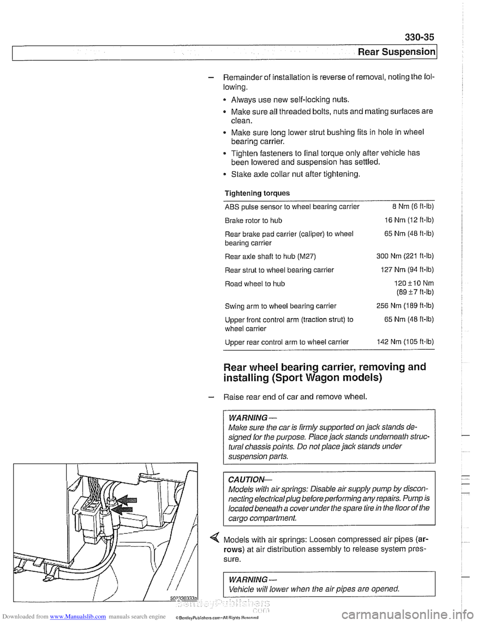
-- 4 Models with air springs: Loosen compressed air pipes (ar-
rows) at air distribution assembly to release system pres-
Page 742 of 1002
Downloaded from www.Manualslib.com manuals search engine
Rear Suspension
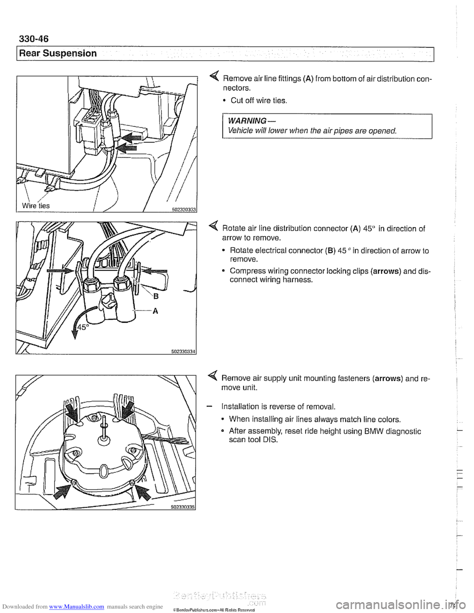
4 Remove air line fittings (A) from bottom of air distribution con-
nectors.
Cut off wire ties.
WARNING-
Vehicle will lower when the air pipes are opened.
4 Rotate air line distribution connector (A) 45" in direction of
arrow to remove.
Rotate electrical connector
(B) 45" in direction of arrow to
remove.
Compress wiring connector locking clips
(arrows) and dis-
connect wiring harness.
< Remove air supply unit mounting fasteners (arrows) and re-
move unit.
- Installation is reverse of removal.
When installing air lines always match line colors.
a After assembly, reset ride height using BMW diagnostic
scan tool DIS.
Page 760 of 1002
Downloaded from www.Manualslib.com manuals search engine
331-16
I Final Drive
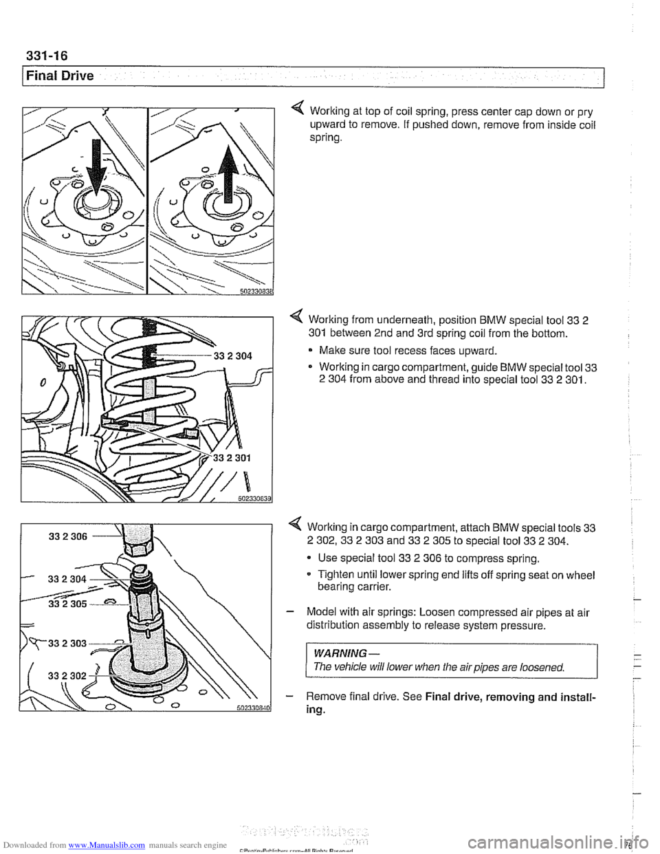
Worlting at top of coil spring, press center cap down or pry
upward to remove. If pushed down, remove from inside coil
spring.
4 Worlting from underneath, position BMW special tool 33 2
301
between 2nd and 3rd spring coil from the bottom.
Make sure tool recess faces upward.
Worlting in cargo compartment, guide BMW special tool
33
2 304
from above and thread into special tool 33 2 301.
4 Worlting in cargo compartment, attach BMW special tools 33
2 302.33
2 303 and 33 2 305 to special tool 33 2 304.
- Use special tool 33 2 306 to compress spring.
Tighten until lower spring end lifts off spring seat on wheel
bearing carrier.
- Model with air springs: Loosen compressed air pipes at air
distribution assembly to release system pressure.
WARNING-
The vehicle will lower when tlie airpipes are loosened.
- Remove final drive. See Final drive, removing and install-
ing.