Heating and ac control module BMW 528i 2000 E39 Workshop Manual
[x] Cancel search | Manufacturer: BMW, Model Year: 2000, Model line: 528i, Model: BMW 528i 2000 E39Pages: 1002
Page 437 of 1002
Downloaded from www.Manualslib.com manuals search engine
Fuel Injection
M5.2 system features
The Bosch M5.2 system used on 1997 540i models uses an
88-pin control unit. The
M5.2 system has the following func-
tions and capabilities:
Fully sequential cylinder-individual fuel injection.
Integrated adaptive knock control.
Oxygen sensor fuel mixture control.
0 Self-diagnosis and emergency operation characteristics.
CAN-Bus link.
0 OED II functions (misfire detection, catalytic converter
monitoring, oxygen sensor monitor, and fuel tank ventila-
tion system).
Electronic vehicle immobilization via EWS.
One-touch starter function.
Control of characteristic map thermostat.
M5.2.1 system features
The Bosch M5.2.1 system is used on 1998 540i models. The
M5.2.1 control module utilizes the SKE (standard shell con-
struction housing) with 5 connectors and a combined total of
134 pins.
The M5.2.1 systefn has
tile following functions or capabilities:
Separate power supply relay for ignition coils. Leak diagnosis pump (LDP) control and feedback
rnonitor-
ing for evaporative system leak testing.
Fuel evaporative system providing ORVR (on-board refuel-
ing vapor recovery) compliancy.
Batterylalternator charge logic (idle speed varied with the
battery state of charge).
CAN-Bus communications with the instrument cluster
EWS
Ill "rolling code" ISN interface.
More sensitive ignition
knock sensors.
Pulse width modulated (P-W-M) Heating and
AIC (IHKA)
status signal.
Running loss (312-way) solenoid valve.
Page 442 of 1002
Downloaded from www.Manualslib.com manuals search engine
.. .-
/Fuel lnjeciion
NOJE-
With engine oft disconnect harness connector and checlc
heating element resistance between white wires on the sen-
sor side of harness. If the element is electrically open (no
continuity), replace sensor.
- If oxygen sensor does not produce a fluctuating voltage and
preheater circuit is
OK, replace sensor.
NOJE-
If not already applied, coat oxygen sensor threads w~th anti-
seize compound before installat~on. Do not get the com-
pound on the sensor tip.
Tightening torque Oxygen sensor to exhaust system
55 Nm (41 ft-lb)
Fuel injectors, checking and replacing
The fuel iniectors are switched on and off (oaened and
closed)
by'the ECM. The injectors are connkcted to acom-
mon power source. A ground signal from the ECM is used to
open and close the injectors.
CA U JIOG
Use only a digital multimeter or an LED injector tester when
testing injectors or wiring. Use of an analog
VOM or incan-
descent test light may damaqe the engine controlmodule.
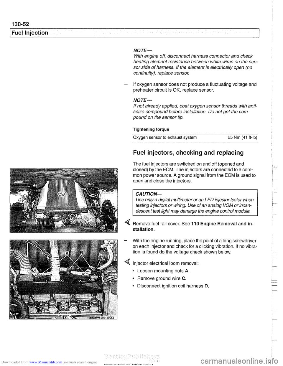
4 Remove fuel rail cover. See 110 Engine Removal and in-
stallation.
With the engine running, place the point of a long screwdriver
on each injector and check for a cliclting vibration.
If no vibra-
tion is found do the voltage
checit shown below.
Injector electrical loom removal:
- Loosen mounting nuts A.
Remove ground wire C.
Disconnect ignition coil harness D
Page 449 of 1002
Downloaded from www.Manualslib.com manuals search engine
130-59
Fuel Injection
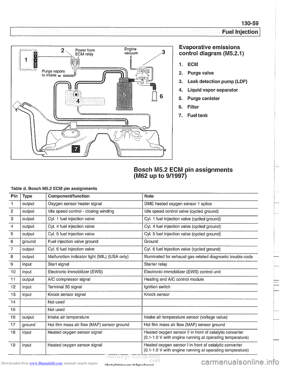
:-- -i. Evaporative emissions
1.
control diagram (M5.2.1)
i 1
i I @ 1. ECM r.=.:-:, 2. Purge valve
3. Leak detection pump (LDP)
4. Liquid vapor separator
5. Purge canister
6. Filter
Bosch M5.2 ECM pin assignments
(M62 up to 911997)
Tabled. Bosch M5.2 ECM pin assignments
I' 1- 1. . . -
4 1 output / Cyl. 4 fuel injection valve I Cyl. 4 fuel injection valve (cycled ground)
Pin
1
2
3
i I
I
7 / output I Cyl. 6 fuel injection valve I Cyl. 6 fuel injection valve (cycled ground)
Type
output
output
output
I I ,
8 1 output I Malfunction indicator light (MIL) (USA only) I lliumlnated for exhaust gas related diagnostic trouble code
5
Component/function
Oxygen sensor heater signal
Idle speed control -closing winding
Cvl. 1 fuel iniection valve Note
DME heated oxygen sensor
1 splice
idle speed control valve (cycled ground)
Cvl. 1 fuel iniection valve lcvcled around)
6 1 ground I Fuel injection valve ground 1 Ground
output
9
Not
used
Not used
11
12
13
Cyl. 5 fuel injection valve
10 1 input I Electronic immobilizer (EWS) / Electronic immobilizer (EWS) control unit
input
Heated oxygen sensor signal Cyl.
5 fuel injection
valve (cycled ground)
output
input
input
16
Start signal Starter relay
NC compressor signal
Terminal
50 signal
Knock sensor signal
17 1 ground I Hot film mass air flow (MAF) sensor ground I Hot film mass air flow (MAF) sensor ground
output Heating and
A/C control module
Ignition switch
Knock sensor
Intake air temperature intake air temperature sensor (voltage value)
Page 451 of 1002
Downloaded from www.Manualslib.com manuals search engine
-. -
Fuel Injection
I 68 1 / Not used
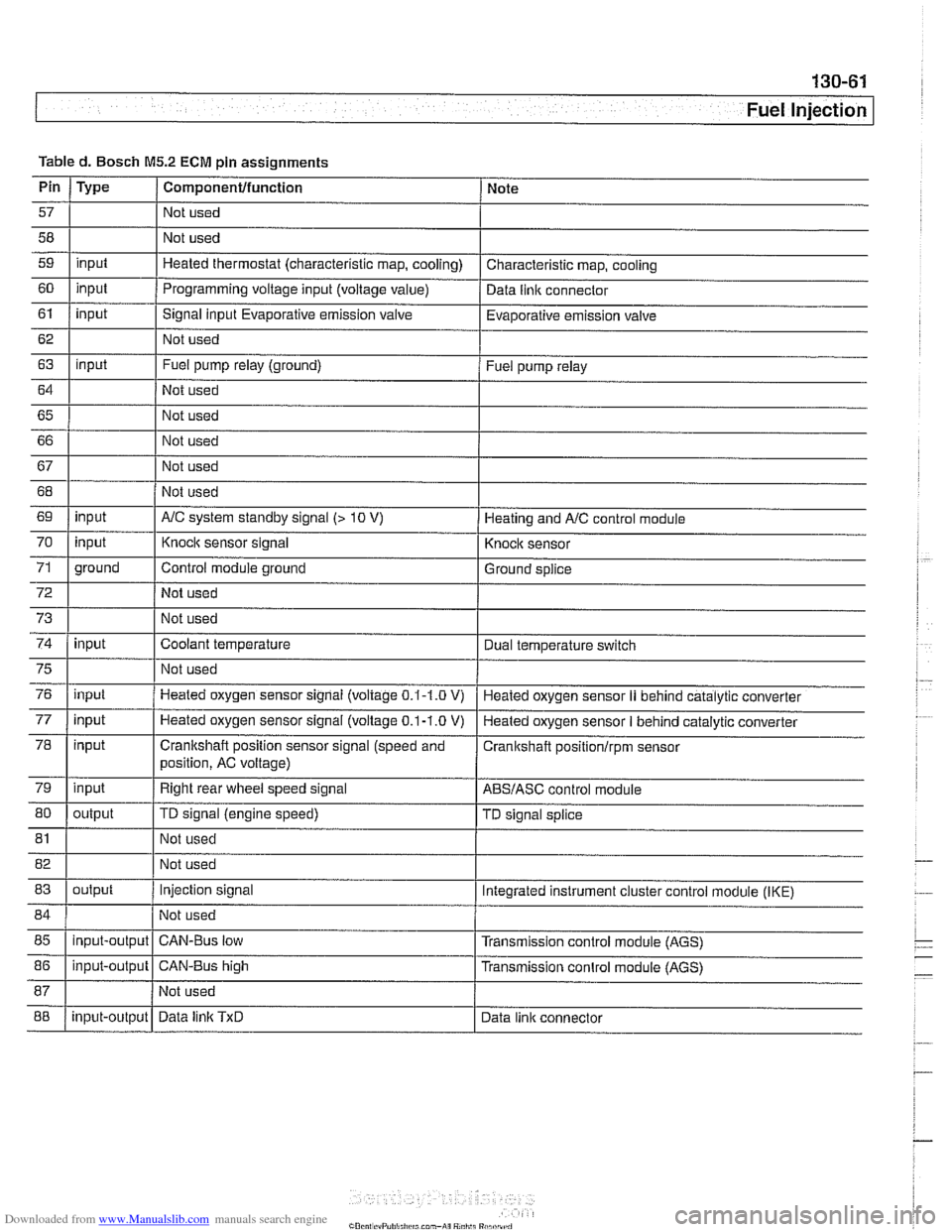
Table
d. Bosch
M5.2 ECM pin assignments
I I I
69 1 input I AIC system standby signal (> 10 V) 1 Heating and AIC control module
Pin
57
58
59
60
61
62
63
64
65 66
67
Type
input
input
input
input
I 70
72
73
74
Componentlfunction
Not used
Not used
Heated thermostat (characteristic map, cooling)
Programming voltage input (voltage
value)
Signal input Evaporative emission valve
Not used
Fuel pump relay (ground)
Not used
Not used
Not used
Not used
75
76
77
78
79
80
Note
Characteristic map, cooling
Data
llnlc connector
Evaporative emission valve
Fuel pump relay
71 1 ground I Control module ground I Ground splice
input
input
81
input input
input
input
output Not used
I
Knock sensor signal
Not used
Not used
Coolant temperature
82 1 I Not used
83
I I
Knock sensor
Dual temperature
swltch
Not used
Heated oxygen sensor signal (voltage
0.1-1.0 V)
Heated oxygen sensor
signal (voltage 0.1-1.0 V)
Crankshaft position sensor signal (speed and
position, AC voltage)
Right rear wheel speed signal
TD signal (engine speed)
85
I I I
Heated oxygen sensor II behind catalytic converter
Heated oxygen sensor
I behind catalytic converter
Cranitshaft positionlrpm sensor
ABSIASC control module
TD signal splice
84 1 / Not used 1
output
88
86
1 input-output 1 CAN-Bus high I Transmission conlrol module (AGS)
input-output
Injection signal
input-output Integrated instrument cluster control
module (IKE)
CAN-Bus low Transmission control module (AGS)
Data
linlc TxD Data link connector
Page 455 of 1002
Downloaded from www.Manualslib.com manuals search engine
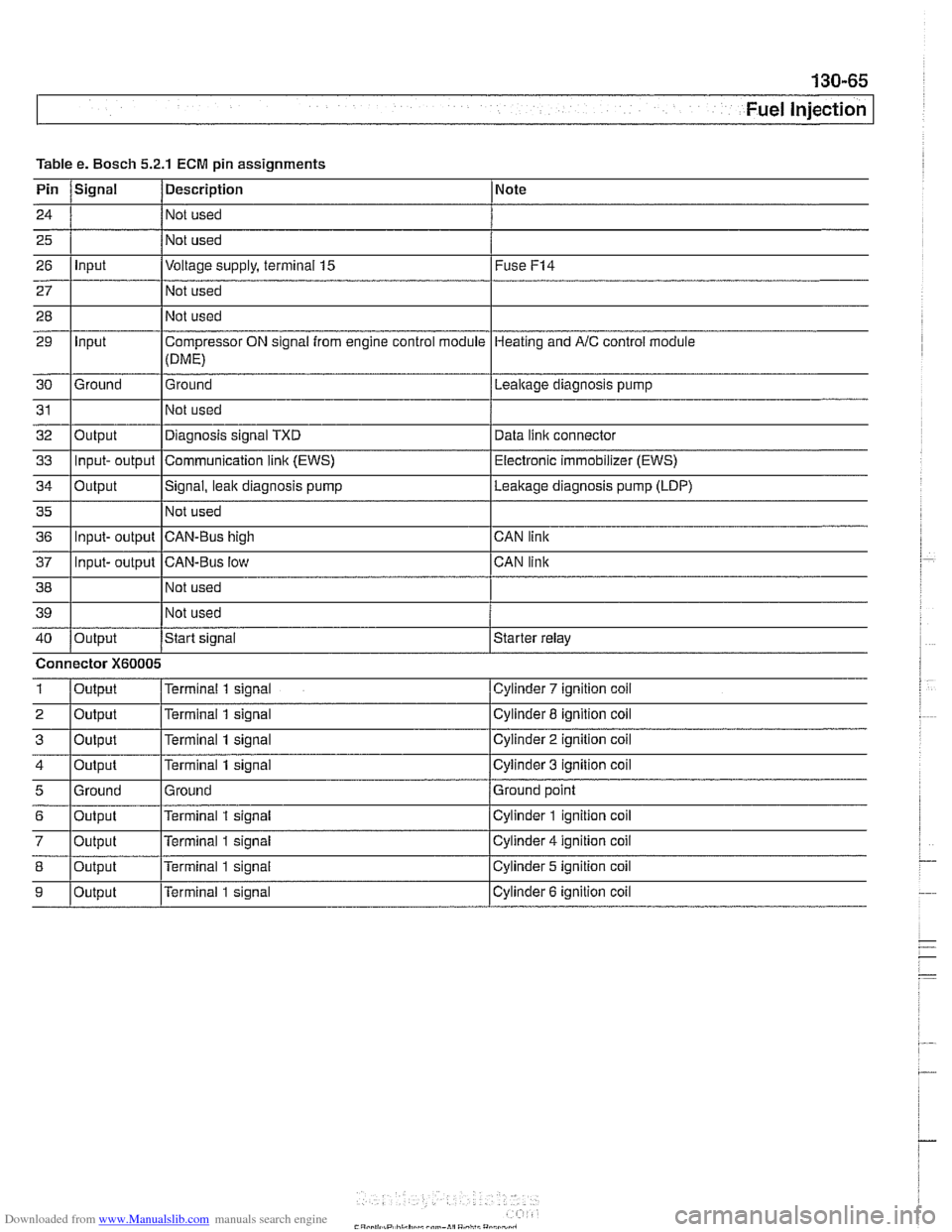
Fuel Injection
Table Pin
24
25
26
27
28
29
30
31
32
33
34
35
36
37
38
39
40
1
2
3
4
5
6
7
8
9
e. Bosch 5.2.1
Signal
Input
Input
Ground
Output Input- output
Output
Input- output
Input- output
Output
Connector
X60005
Output
Output
Output
Output
Ground
Output
Output
Output
Output
ECM pin assignments
Description
Not used
Not used
Voltage supply, terminal
15
Not used
Not used
Compressor ON signal from engine control module
(DME)
Ground
Not used
Diagnosis signal TXD
Communication
link (EWS)
Signal, leak diagnosis pump
Not used
CAN-Bus high
CAN-Bus low Not used
Not used
Start
signal
Terminal 1 signal
Terminal
1 signal
Terminal
1 signal
Terminal
1 signal
Ground
Terminal
1 signal
Terminal
1 signal
Terminal
1 signal
Terminal 1 signal Note
Fuse
F14
Heating
and AIC control module
Lealtage diagnosis pump
Data
iinit connector
Electronic immobilizer (EWS)
Leakage diagnosis pump (LDP)
CAN link
CAN link
Starter relay
Cylinder
7 ignition coil
Cylinder 8 ignition coil
Cylinder
2 ignition coil
Cylinder
3 ignition coil
Ground point
Cylinder
1 ignition coil
Cylinder
4 ignition coil
Cylinder 5 ignition coil
Cylinder
6 ignition coil
Page 469 of 1002
Downloaded from www.Manualslib.com manuals search engine
Fuel Injection I
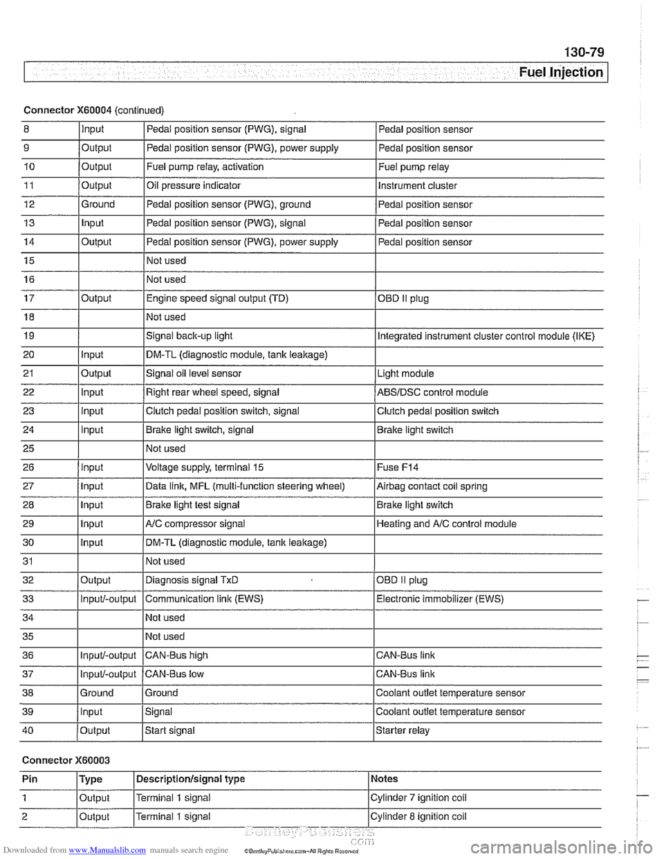
Connector X60004 (continued)
8 10
11
12
13
14
15
16
9
Output 0
Input
17
18
19
20
21
22
23
24
25
26
27
28
29
30
31
32
33
34
35
36
39
llnput lsignal l~oolant outlet temperature sensor
Output
Output
Ground
Input
Output
I I - I
40 /output Istart signal Istarter relay
Pedal position sensor (PWG), signal
Output Input
Output
input
Input
Input
Input
Input
Input
input
Input
Output
Input/-output
Input/-output
37
Connector X60003
Pedal position sensor
Fuel pump relay, activation
Oil pressure indicator Pedal position sensor (PWG), ground
Pedal position sensor (PWG), signal
Pedal position sensor (PWG), power supply
Not used
Not used Fuel
pump relay
Instrument cluster
Pedal position sensor
Pedal position sensor
Pedal position sensor
Engine speed signal output (TD)
Not used
Signal
back-up light
DM-TL (diagnostic module,
tank leakage)
Signal oil level sensor
Right rear wheel speed, signal
Clutch pedal position switch, signal
Brake light switch, signal
Not used
Voltage supply, terminal
15
Data link, MFL (multi-function steering wheel)
Brake light test signal
AJC compressor signal
DM-TL (diagnostic module, tank
leakage)
Not used
Diagnosis signal
TxD
Communication link (EWS)
Not used
Not used
CAN-BUS hiqh
38 1 Ground l~round I Coolant outlet temperature sensor
OED II plug
Integrated instrument cluster control module (IKE)
Light module
ABSIDSC control module
Clutch pedal position switch
Brake light switch
Fuse
F14
Airbag contact coil spring
Brake light switch
Heating and
A/C control module
OBD
II plug
Electronic immobilizer (EWS)
CAN-Bus link
CAN-Bus link
Input/-output CAN-Bus low
Page 503 of 1002
Downloaded from www.Manualslib.com manuals search engine
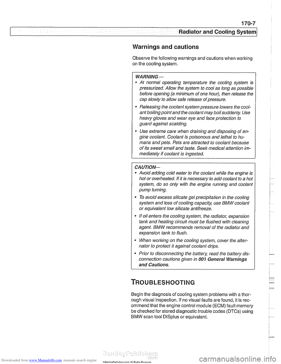
Warnings and cautions
Obse~e the following warnings and cautions when worlting
on the cooling system.
WARNING -
. At normal operating temperature the cooling system is
pressurized. Allow the system to cool as long as possible
before opening (a minimum of one hour), then release the
cap slowly to allow safe release ofpressure.
a Releasing the coolant system pressure lowers the cool-
ant boilingpoint and the coolant may boil suddenly. Use
1 heavy and wear eye and face protection to
guard against scalding.
Use extreme care when draining and disposing of en-
gine coolant. Coolant is poisonous and lethal to hu-
mans andpets. Pets are attracted to coolant because
of its sweet smell and taste. Seek medical attention im-
mediately if coolant is ingested.
CAUTIOG
Avoid adding cold water to the coolant while the engine is
hot or overheated. If it is necessary to add coolant to a
hol
system, do so only with the engine running and coolanl
pump turning.
To avoid excess silicate gel precipitation in the cooling
system and loss of cooling capacity, use BMW coolant
or equivalent low silicate antifreeze.
a If oil enters the cooling system, the radiator, expansion
tank and heating circuit must be flushed with cleaning
agent. BMW recommends removal of the radiator and
expansion
tank to flush.
When
worlcing on the cooling system, cover the alter-
nator to protect it against coolant drips.
Prior to disconnecting the battery, read the battery dis-
connection cautions given in
001 General Warnings
and Cautions.
Begin the diagnosis of cooling system problems with a thor-
ough visual inspection.
If no visual faults are found, it is rec-
ommend that the engine control module (ECM) fault memory
be checked for stored diagnostic trouble codes
(DTCs) using
BMW scan tool
DlSplus or equivalent.
Page 804 of 1002
Downloaded from www.Manualslib.com manuals search engine
400-1 0
Body-General
Seats
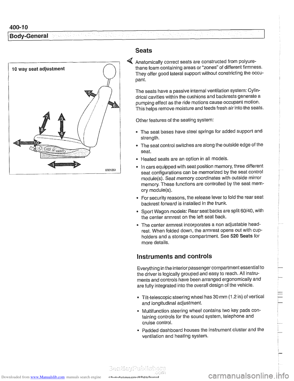
4 Anatomically correct seats are constructed from polyure-
10 way seat adjustment thane foam
containing areas or "zones" of different firmness.
They offer good lateral support without constricting the occu-
pant.
The seats have a passive internal ventilation system: Cylin-
drical cavities within the cushions and backrests generate a
pumping effect as the ride motions cause occupant motion.
This
helps remove moisture and feeds fresh air into the seats.
Other features of the seating system:
The seat bases have steel springs for added support and
strength.
The seat control switches are along the outside edge of
the
seat.
Heated seats are an option in all models
In cars equipped with seat position memory, three different
seat confiaurations can be memorized by the seat control
module(s): Seat memory coordinates with outside mirror
memory. These functions are controlled by the seat mem-
ory
module(s).
* For security reasons, the release lever to fold the rear seat
backrest forward is installed in the trunk.
Sport Wagon models: Rear seat
baclts are split 60140, with
the center armrest on the left seat back.
The center armrest incorporates a non adjustable head-
rest. When folded down, the armrest opens out with
cup-
holders and a storage compartment. See 520 Seats for
more details.
instruments and controls
Everything in the interior passengercompartment essential to
the driver is logically grouped and easy to reach. All instru-
ments and controls have been arranged ergonomically and
are fully integrated into the overall design of the vehicle.
Tilt-telescopic steering wheel has
30 mm (1.2 in) of vertical
and longitudinal adjustment.
Multifunction steering wheel contains two
ltey pads con-
taining controls for the sound system, telephone and
cruise control.
Padded dashboard houses the instrument cluster and the
ventilation and heating system.
Page 880 of 1002
Downloaded from www.Manualslib.com manuals search engine
I lnterior Trim
This repair group covers interior trim removal and installation
procedures.
- Refer to the following repair groups for additional information:
250 Gearshift Linkage
41 1 Doors (interior door panels)
@ 612 Switches
620 Instruments
640 Heating and Air Conditioning [IHKA control panel!
650 Radio
721 Airbag System (SRS)
lnterior trim repairs
lnterior trim and finish panels are clipped or screwed into
place. Many of the trim retaining clips are designed
to be used
only once. When removing trim that is held in place with clips,
it is a good idea to have spare clips on hand before beginning
the job.
WARNING-
Special precautions must be observed when servicing the
BMWSupplementai Restraint System (SRS). Serious inju-
ry may result if system service is attempted by persons un-
familiar with the BMW
SRS and its approved service
procedures. BMW
speciiies that all inspection and service
should be performed by an authorized BMW
dealer.
Before performing any work involving airbags, discon-
nect the negative
() battery cable. See 721 Airbag
System (SRS).
Airbags contain a back-uppowersupply within the SRS
control module. A
5 second discharge period should be
allowed after the battery cable has been disconnected.
CAUTION-
* When working on electrical switclies or lights, always dis-
connect the negative
(-) cable from the battery and insu-
late the cable end to prevent accidental reconnection.
a Prior to disconnecting the battery, read the battery dis-
connection cautions given in
W1 General Warnings
and Cautions.
To prevent marring the trim when working on interior
components, work with plastic prying
tools or wrap the
tips of screwdrivers and pliers with tape before prying
Page 906 of 1002
Downloaded from www.Manualslib.com manuals search engine
51 5-12
I Central Locking and Anti-Theft
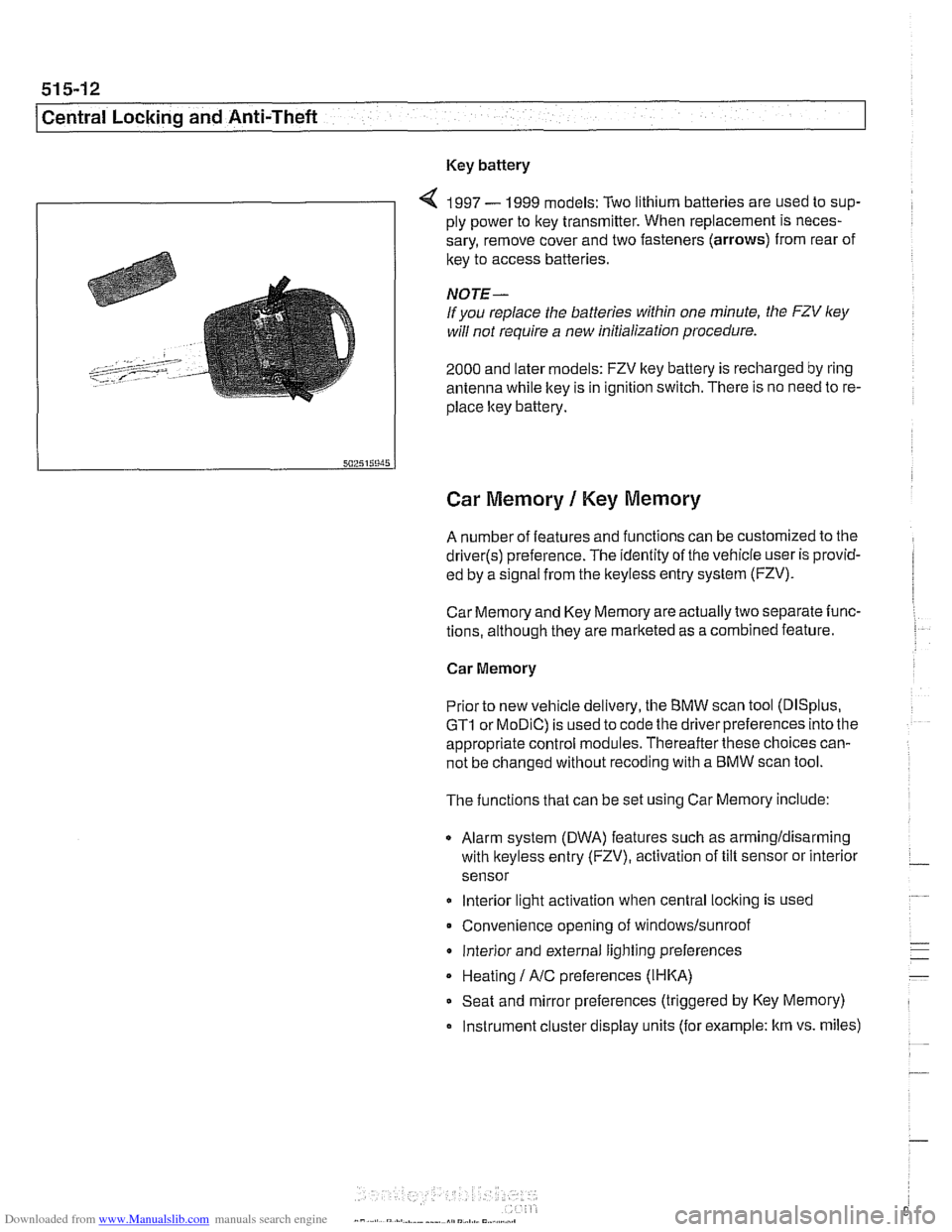
Key battery
9
4 1997 - 1999 models: Two lithium batteries are used to sup-
ply power to key transmitter. When replacement is neces-
sary, remove cover and two fasteners (arrows) from rear of
key to access batteries
NOTE-
If you replace the batteries within one minute, the FZV ley
will not require a new initialization procedure.
2000 and later models: FZV key battery is recharged by ring
antenna while ltey is in ignition switch. There is no need to re-
place ltey battery.
Car Memory 1 Key Memory
A number of features and functions can be customized to the
driver(s) preference. The identity of the vehicle user is provid-
ed by a
s~gnal from the keyless entry system (FZV).
Car Memory and Key Memory are actually two separate func-
tions, although they are marketed as a combined feature.
Car Memory
Pr'or ro new
veh c,e de very, the BMW scan roo (DISp us,
GTI or MOD C) is ~sed lo cooc ine driver preierences nro ine
appropriate control modules. Thereafter these choices can-
not be changed without
recoding with a BMW scan tool.
The functions that can be set using Car Memory include:
Alarm system (DWA) features such as armingldisarming
with
lkeyless entry (FZV), activation of tilt sensor or interior
sensor
lnterior light activation when central
locking is used
Convenience opening of
windows/sunroof
lnterior and external lighting preferences
Heating
I A/C preferences (IHKA)
Seat and mirror preferences (triggered by Key Memory)
Instrument cluster display units (for example: km vs. miles)