Lamps BMW 528i 2000 E39 Workshop Manual
[x] Cancel search | Manufacturer: BMW, Model Year: 2000, Model line: 528i, Model: BMW 528i 2000 E39Pages: 1002
Page 54 of 1002
Downloaded from www.Manualslib.com manuals search engine
020-22 Maintenance
1
- Installation is reverse of removal, bearing in mind the
following:
Lightly lubricate new
spark plug threads with
copper-based anti-seize compound.
Thread plugs into cylinder head by hand to prevent
cross-threading.
. Be sure to reinstall and tighten coil grounds.
Tightening torque Spark plug
to cylinder head 25 Nm (18 It-lb)
Interior ventilation microfilter, replacing
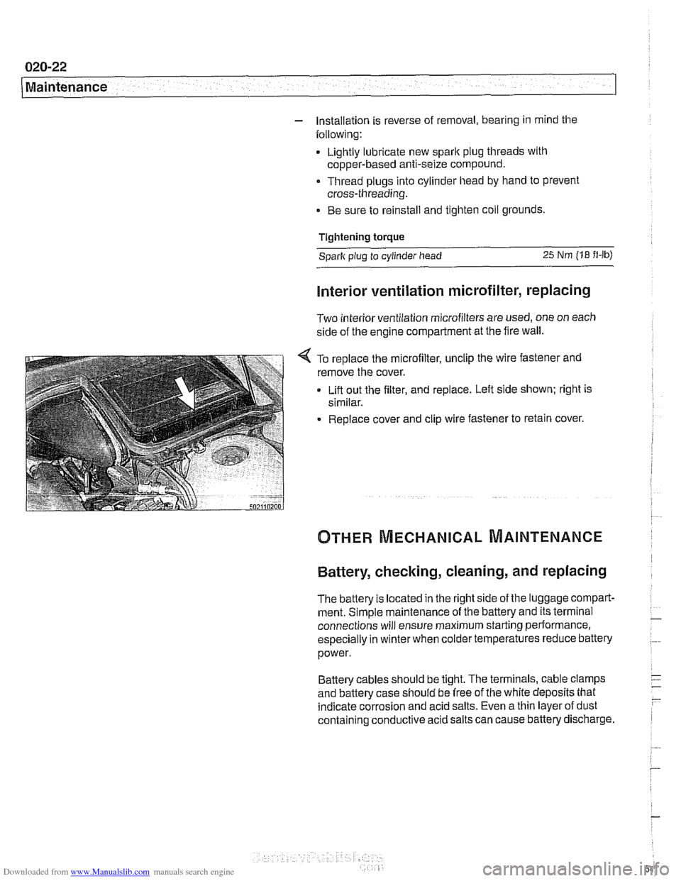
Two interior ventilation microfilters are used, one on each
side of the engine compartment at the fire wall.
< To replace the microfilter, unclip the wire fastener and
remove the cover.
Lift out the filter, and replace. Left side shown; right is
similar.
Replace cover and clip wire fastener to retain cover.
Battery, checking, cleaning, and replacing
The battery Is located in the right side of the luggage compart-
ment. Simple maintenance of the battery and its terminal
connections will ensure maximum starting periormance,
especially in winter when colder temperatures reduce battery
power.
Battery cables should be tight. The terminals, cable clamps
and battery case should be free of the white deposits that
indicate corrosion and acid salts. Even a thin layer of dust
containing conductive acid salts can cause battery discharge.
Page 55 of 1002
Downloaded from www.Manualslib.com manuals search engine
Maintenance
- To remove battery corrosion:
Disconnect battery cables. Disconnect negative (-)cable
first.
* Remove battery from trunk
Clean terminal posts and cable clamps with a wire brush.
Clean main chassis ground terminal next to battery.
Corrosion can be washed away with a
baking soda and
water solution that will neutralize acid.
Reinstall battery and reconnect cable clamps, positive
(+)
cable first.
Lightly coat outside of terminals, hold down screws, and
clamps with petroleum jelly, grease, or a commercial
battery terminal corrosion inhibitor.
WARNING
-
Battery acid is extremely dangerous. Take care to keep it
from contacting eyes, skin, or clothing. Wear eye protection.
Extinguish all
smolihg materials and do not work near any
oaen flames.
CAUTION-
Prior to disconnecting the batteg read the battery discon-
nection cautions given in
001 General Cautions and
Warnings.
NOTE-
The original equipment battery in E39 models is mainte-
nance free. The original electrolyte will normally last the
entire service life of the battery under moderate climate con-
ditions.
Battery electrolyte should be maintained at the correct level
just above the battery plates and theirseparators. The correct
level is approximately
5 mm ('14 in.) above the top of battery
plates or to the top of the indicator
marks (if applicable). The
battery plates and the indicator marks can be seen once the
fillercaps are removed.
if theelectrolyte level is low, replenish
it by adding distilled water only.
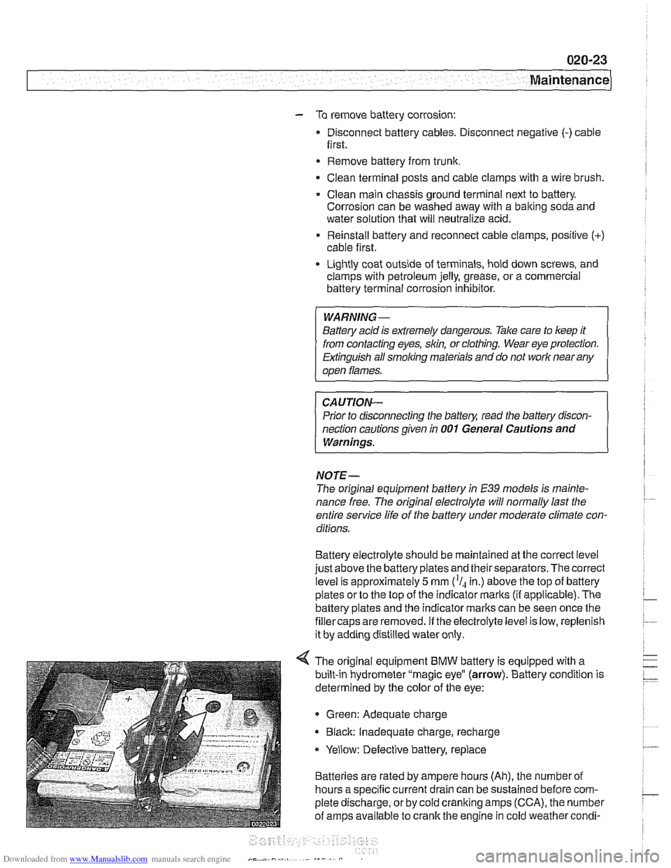
4 The original equipment BMW battery is equipped with a
built-in hydrometer "magic eye"
(arrow). Battery condition is
determined by the color of the eye:
Green: Adequate charge
* Black: Inadequate charge, recharge
Yellow: Defective battery, replace
Batteries are rated by ampere hours (Ah), the number of
hours a specific current drain can be sustained before com-
plete discharge, or by cold cranking amps (CCA), the number
of amps available to crank the engine in cold weather
condi-
Page 60 of 1002
Downloaded from www.Manualslib.com manuals search engine
020-28
1 Maintenance
- When replacing fuel filter:
Use appropriate hose clamping device to clamp off filter
inlet and outlet hoses to lessen fuel spillage.
Loosen center clamping bracket and hose clamps on
either end of filter.
Note arrow or markings indicating direction of flow on
new filter.
Install new filter using new hose clamps
- Drain fuel filter from inlet side into a container and inspect
drained fuel.
Checlc for rust, moisture and contamination.
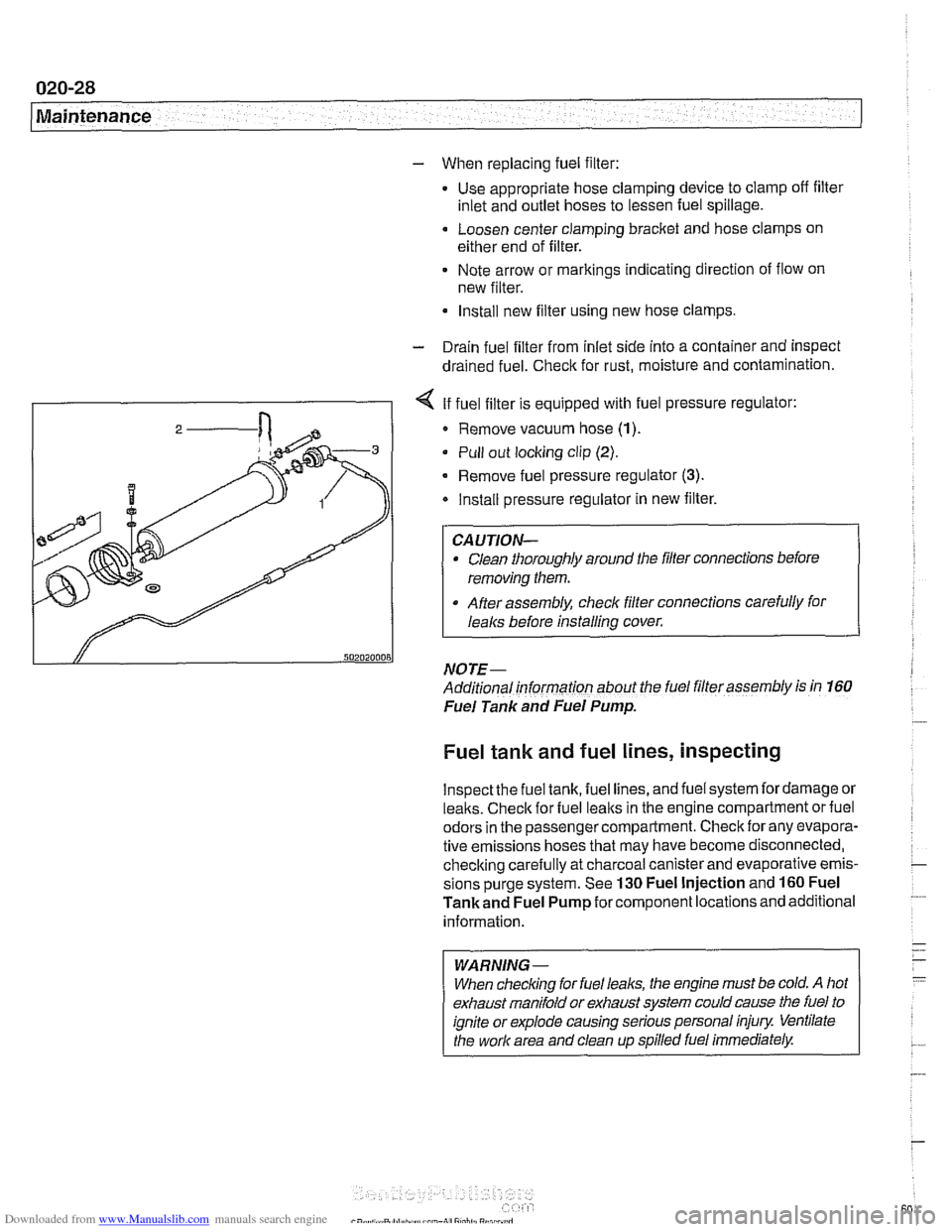
I - I < If fuel filter is equipped with fuel pressure regulator:
I 2 / Remove vacuum hose (1)
Pull out locking clip (2).
- Remove fuel pressure regulator (3).
Install pressure regulator in new filter.
Clean thoroughly around the filler connections before
removing them.
After assembly, check filter connections carefully for
I
I lealcs before installing cover.
NOTE- ~-
Additional informarion about the fuel filler assembly is in 160
Fuel Tank and Fuel Pump.
Fuel tank and fuel lines, inspecting
lnspectthe fuel tank, fuel lines, and fuel system fordamage or
lealts. Checlc for fuel lealts in the engine compartment or fuel
odors in the passenger compartment. Check for any evapora-
tive emissions hoses that may have become disconnected,
checking carefully at charcoal canister and evaporative emis-
sions purge system. See
130 Fuel Injection and 160 Fuel
Tankand Fuel Pump for component locations and additional
information.
WARNING-
When checlcing for fuel leal(s, the engine must be cold. A hot
exhaust manifold or exhaust system could cause the fuel to
ignite or explode causing serious personal injury Ventilate
the work area and clean up spilled fuel immediately.
Page 84 of 1002
Downloaded from www.Manualslib.com manuals search engine
110-12
Engine Removal and Installation
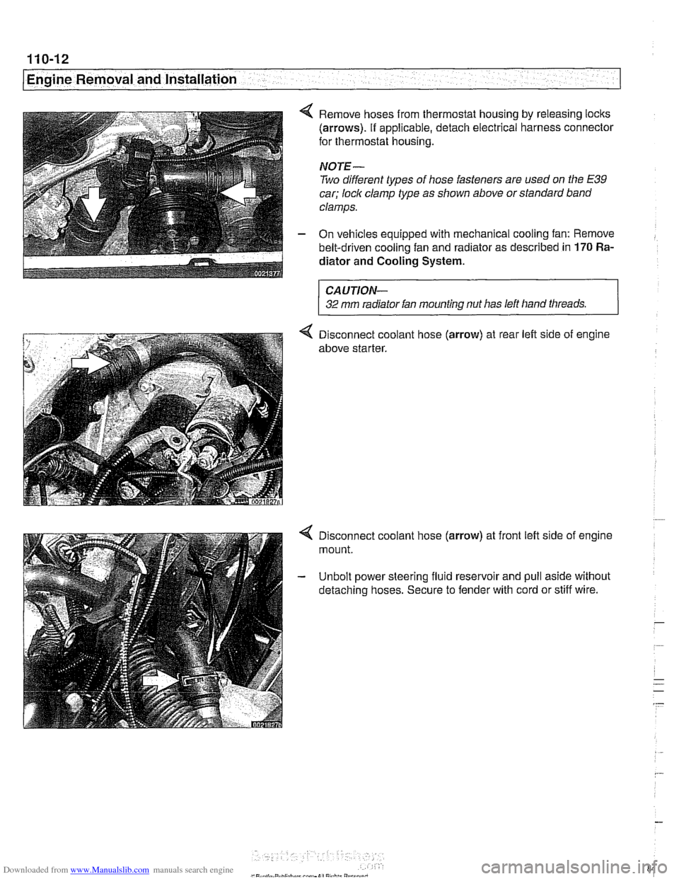
4 Remove hoses from thermostat housing by releasing locks
(arrows). If applicable, detach electrical harness connector
for thermostat housing.
NOTE-
Two different types of hose fasteners are used on the E39
car; lock clamp type as shown above or standard band
clamps.
- On vehicles equipped with mechanical cooling fan: Remove
belt-driven cooling fan and radiator as described in
170 Ra-
diator and Cooling
System.
CAUTION-
32 mm radiator fan mounting nut has left hand threads.
4 Disconnect coolant hose (arrow) at rear left side of engine
above starter.
4 Disconnect coolant hose (arrow) at front left side of engine
mount.
- Unbolt power steering fluid reservoir and pull aside without
detaching hoses. Secure to fender with cord or stiff wire.
Page 216 of 1002
Downloaded from www.Manualslib.com manuals search engine
-. .
Cylinder Head and Valvetrain -- v . -- --- --
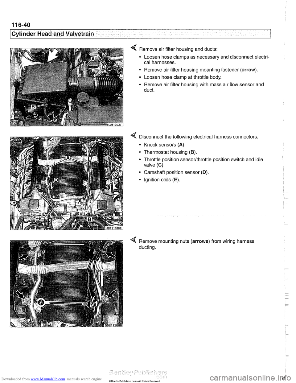
4 Remove air filter housing and ducts:
Loosen hose clamps as necessary and disconnect electri-
cal harnesses.
- Remove air filter housing mounting fastener (arrow).
Loosen hose clamp at throttle body.
Remove air filter housing with mass air flow sensor and
duct.
Disconnect the following electrical harness connectors.
Knoclc sensors (A).
Thermostat housing (B).
Throttle position sensor/throttle position switch and idle
valve
(C).
Camshaft position sensor (D).
* Ignition coils (E).
Remove mounting nuts (arrows)
ducting. from
wiring harness
Page 335 of 1002
Downloaded from www.Manualslib.com manuals search engine
... . . Lubrication sy=
Upper oil pan, removing and installing (V-8)
The engine oil pan removal procedure requires that the en-
gine be supported from the top and the front suspension
sub-
frame be lowered.
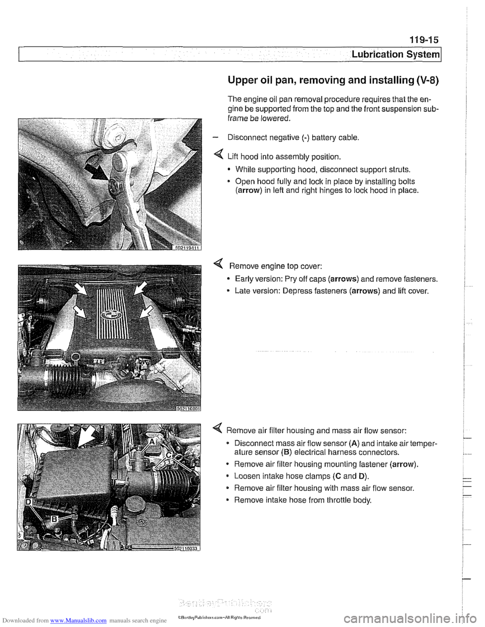
- Disconnect negative (-) battery cable
4 Lift hood into assembly position.
- While supporting hood, disconnect support struts.
Open hood
fully and lock in piace by installing bolts
(arrow) in left and right hinges to lock hood in place
4 Remove engine top cover:
- Early version: Pry off caps (arrows) and remove fasteners.
Late version: Depress fasteners (arrows) and lift cover.
4 Remove air filter housing and mass air flow sensor:
Disconnect mass air flow sensor
(A) and intake air temper-
ature sensor
(B) electrical harness connectors.
Remove air filter housing mounting fastener (arrow)
Loosen
intake hose clamps (C and D).
Remove air filter housing with mass air flow sensor.
Remove intake hose from throttle body.
Page 363 of 1002
Downloaded from www.Manualslib.com manuals search engine
120-15
Ignition system1
Exhaust camshaft position sensor, replacing
(M52 TU and M54 engines)
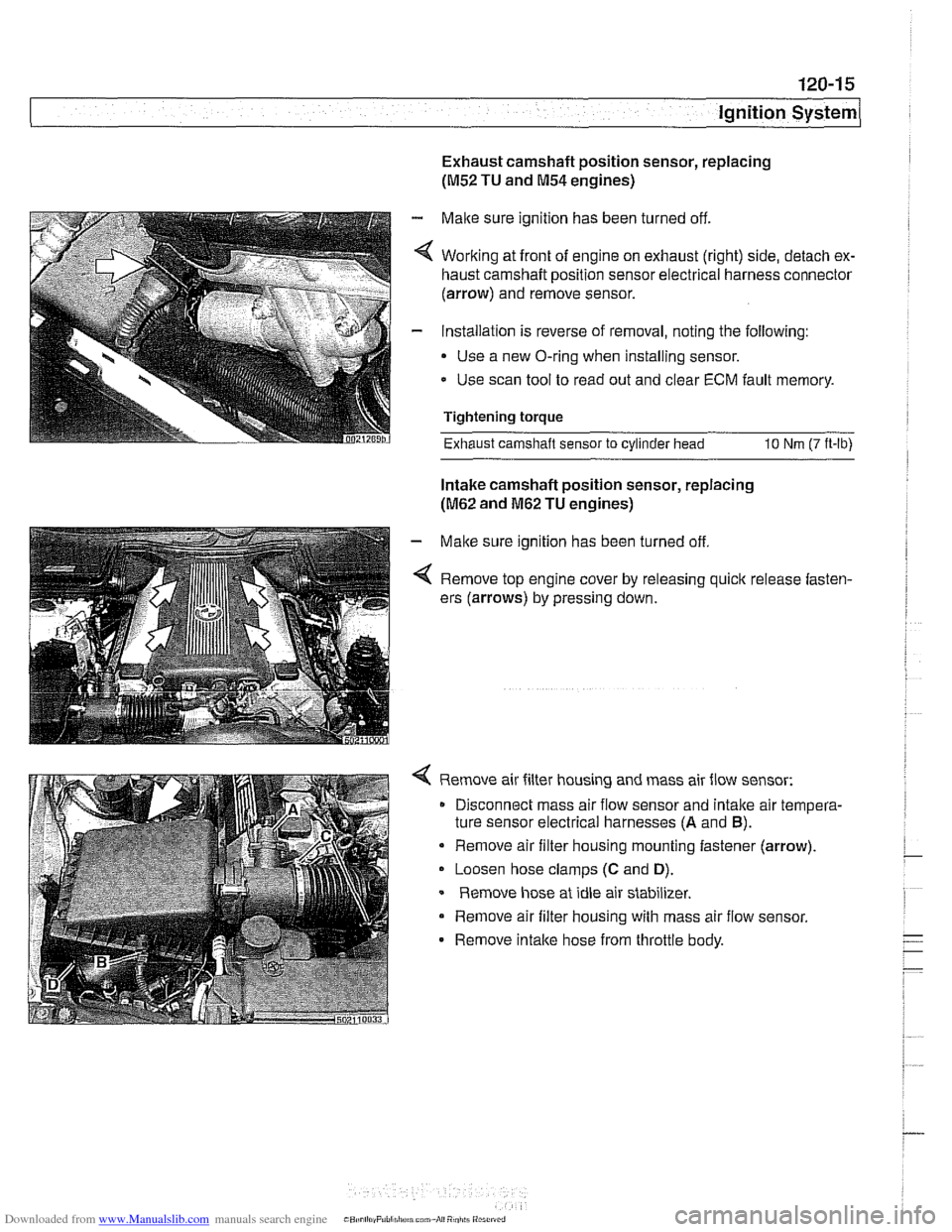
- Make sure ignition has been turned off.
4 Working at front of engine on exhaust (right) side, detach ex-
haust camshaft position sensor electrical harness connector
(arrow) and remove sensor.
- Installation is reverse of removal, noting the following:
Use a new O-ring when installing sensor.
- Use scan tool to read out and clear ECM fault memory.
Tightening torque
Exhaust camshaft sensor
to cylinder head 10 Nm (7 ft-lb)
Intake camshaft position sensor, replacing
(M62 and M62 TU engines)
- Make sure ignition has been turned off
4 Remove top engine cover by releasing quick release fasten-
ers (arrows) by pressing down.
4 Remove air filter housing and mass air flow sensor:
Disconnect mass air flow sensor and
intalte air tempera-
ture sensor electrical harnesses
(A and B).
Remove air filter housing mounting fastener (arrow).
Loosen hose clamps
(C and D).
Remove hose at idle air stabilizer.
Remove air filter housing with mass air flow sensor.
- Remove intalte hose from throttle body.
Page 395 of 1002
Downloaded from www.Manualslib.com manuals search engine
Fuel Injection
Warnings and cautions
For personal safety, as well as the protection of sensitive
electronic components, adhere to the warnings and cautions
on the following pages.
WARNING-
Gasoline is highly flammable and its vapors are explosive.
Do not smoke or work on a car near heaters or other fire
hazards when diagnosing and repairing fuel system prob-
lems. Have a fire extinguisher available in case of an emer-
gency
Renew fuel system hoses, clamps and O-rings any
time they are removed.
When working on an open fuel system, wear suitable
hand protection, as prolonged contact
with fuel can
cause illnesses and skin disorders.
* The ignition system produces high voltages that can be
fatal. Avoid contact with exposed terminals. Use ex-
treme caution when
working on a car with the ignition
switched on or the engine running.
CAUTION-
- Disconnecting the battery may erase fault code($ storedin
memory Check for fault codes prior to disconnecting the
battery cables. Read the battery disconnection cautions in
001 General Warnings and Cautions.
a Connect and disconnect the DME system wiring and
1 test equipment leads only when the ignition is switched
off.
Wait at least 1 minute after turning off the ignition be-
fore removing the engine control module (ECM) con-
nector. If the connector is removed before this time,
residualpower in the system relay may damage the
control module.
Fuel system cleaners and other chemical additives oth-
er than those specifically recommended by BMW may
damage the catalytic converter, the oxygen sensor or
other fuel supply components.
* Do not connect any test equipment that delivers a 12-
volt power supply to terminal 15 (+) of the ignition coil.
The current flow may damage the ECM. In general,
connect test equipment only as specified by BMW or
the equipment maker.
Only use a digital
multirneter for electrical tests. Only
use an LED test light for
quiclc tests.
Page 447 of 1002
Downloaded from www.Manualslib.com manuals search engine
Fuel Injection
Intake air temperature
([AT) sensor,
testing and replacing
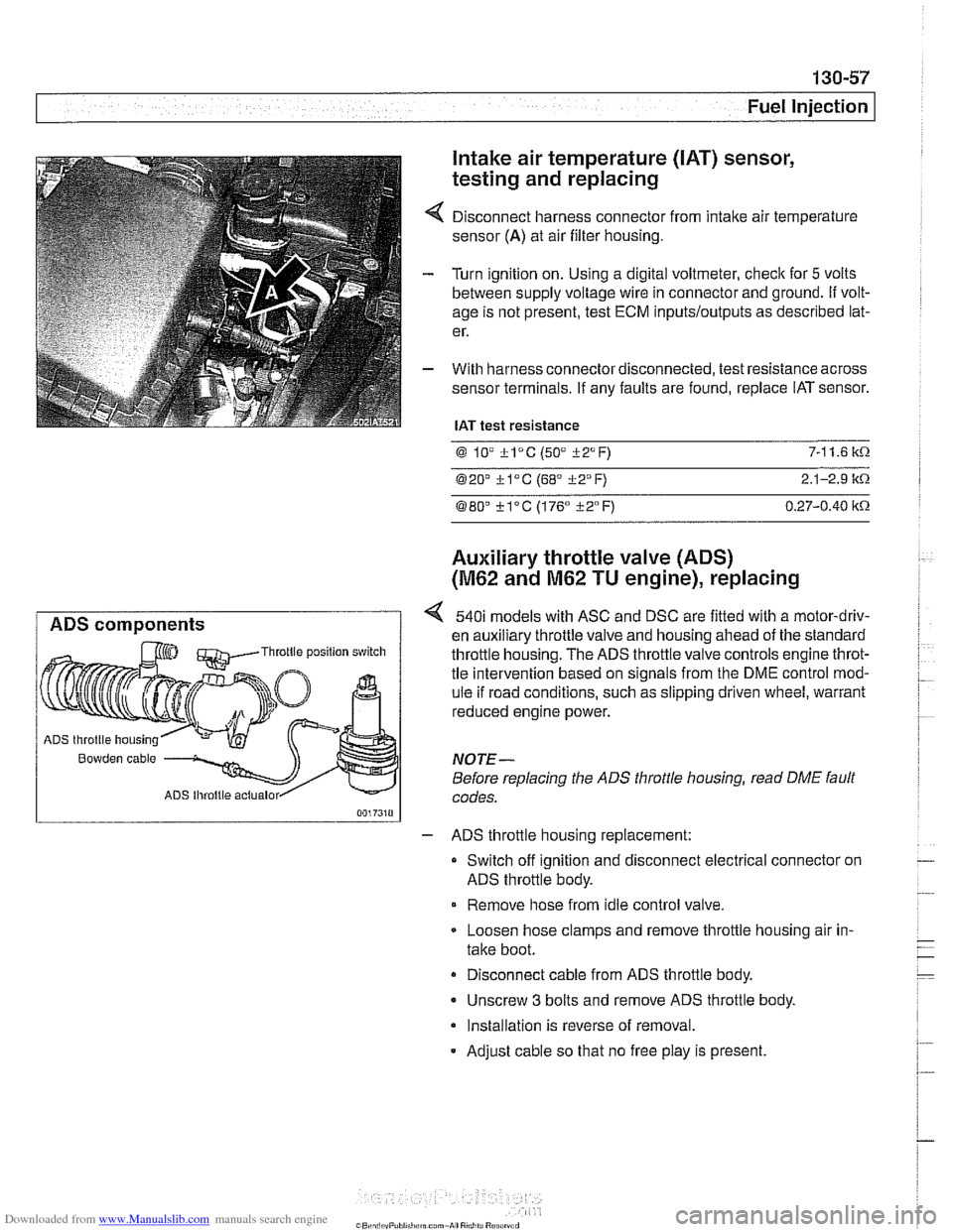
Disconnect harness connector from intake air temperature
sensor
(A) at air filter housing.
Turn ignition on. Using a digital voltmeter, check for
5 volts
between supply voltage wire in connector and ground.
If volt-
age is not present, test ECM
inputs/outputs as described lat-
er.
With harness connector disconnected, test resistance across
sensor terminals. If any faults are found, replace IAT sensor.
IAT test resistance
0 lV *lac (50" i-2°F) 7-1 1.6 k.0.
020' kl°C (68' 322°F) 2.1-2.9 it.0.
080" ?lac (176" i-2°F) 0.27-0.40 itn
Auxiliary throttle valve (ADS)
(M62 and M62 TU engine), replacing
ADS components 540i models with ASC and DSC are fitted with a motor-driv-
en auxiliary throttle valve and housing ahead of the standard Throttle position switch throttle housing. The ADS throttle valve controls engine throt-
tle intervention based on signals from the DME control mod-
ule if road conditions, such as slipping driven wheel, warrant
reduced engine power.
ADS throttle housing
Bowden cable NOTE-
Before replacing the ADS throttle housing, read DME fault
ADS lhroltle actualor codes.
- ADS throttle housing replacement:
Switch off ignition and disconnect electrical connector on
ADS throttle body.
Remove hose from idle control valve.
Loosen hose clamps and remove throttle housing air in-
take boot.
Disconnect cable from ADS throttle body.
- Unscrew 3 bolts and remove ADS throttle body.
Installation is reverse of removal.
- Adjust cable so that no free play is present.
Page 463 of 1002
Downloaded from www.Manualslib.com manuals search engine
( Mass Air Flow Sensor
1" Intake air temp. (NTC)
Sensor qround
Reference voltage . . . -., f fitr mass signal I
Fuel Injection I
Release fuel injector locking clips (arrow).
- Remove fuel injector loom boxes and lay to one side.
- Remove 4 fuel rail mounting fasteners.
4 Disconnect fuel line at quick-disconnect. To disconnect,
press in plastic collar (arrow) and separate fuel line.
WARNING -
Fuel may be expelled underpressure. Do not srnol(e or work
near heaters or
other fire hazards. Keep a fire extinguisher
handy. Before disconnecting fuel hoses, wrap a cloth around
fuel hose
to absorb anv leakinq fuel. Plug all open fuel lines.
- Lifl fuel rail and injectors straight up to remove.
- lnstallation is reverse of removal. Use new injector seals and
clamps during installation.
Mass air flow (MAF) sensor,
removing and installing
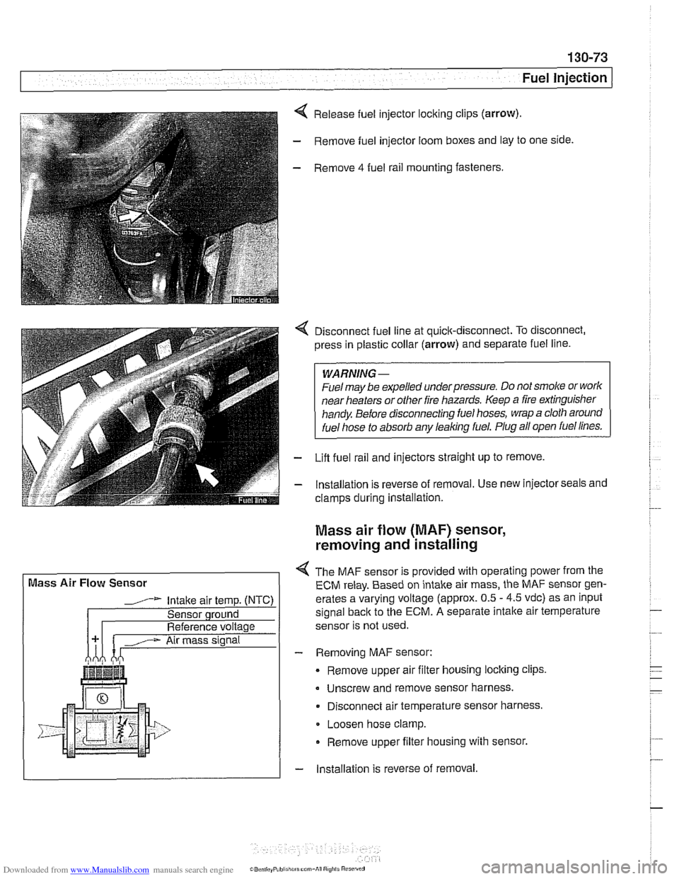
4 The MAF sensor is provided with operating power from the
ECM relay. Based on intake air mass, the MAF sensor gen-
erates a varying voltage (approx. 0.5
- 4.5 vdc) as an input
signal
back to the ECM. A separate intalte air temperature
sensor is not used.
- Removing MAF sensor:
Remove upper air filter housing locking clips
Unscrew and remove sensor harness.
Disconnect air temperature sensor harness.
Loosen hose clamp.
Remove upper filter housing with sensor.
- lnstallation is reverse of removal