Replace engine wire harness BMW 528i 2000 E39 Workshop Manual
[x] Cancel search | Manufacturer: BMW, Model Year: 2000, Model line: 528i, Model: BMW 528i 2000 E39Pages: 1002
Page 52 of 1002
Downloaded from www.Manualslib.com manuals search engine
Maintenance
continue to operate as designed. Extending the replacement
interval may void the emission control warranty coverage.
See
180 Exhaust System for information on replacing the
oxygen sensors.
Tightening torque
Oxvoen sensor to exhaust
manifold 50 Nrn (37 ft-lb)
NOTE-
A special soclet for replacing the oxygen sensor is available
from most automotive parts stores. The soclet has
a groove
cut down one side to allow the sensor to be installed without
damaging the wire harness.
Power steering fluid, checking level
The power steering system is permanently filled and does not
have a drain. Routinely adding ATF is not required unless the
system is leaking.
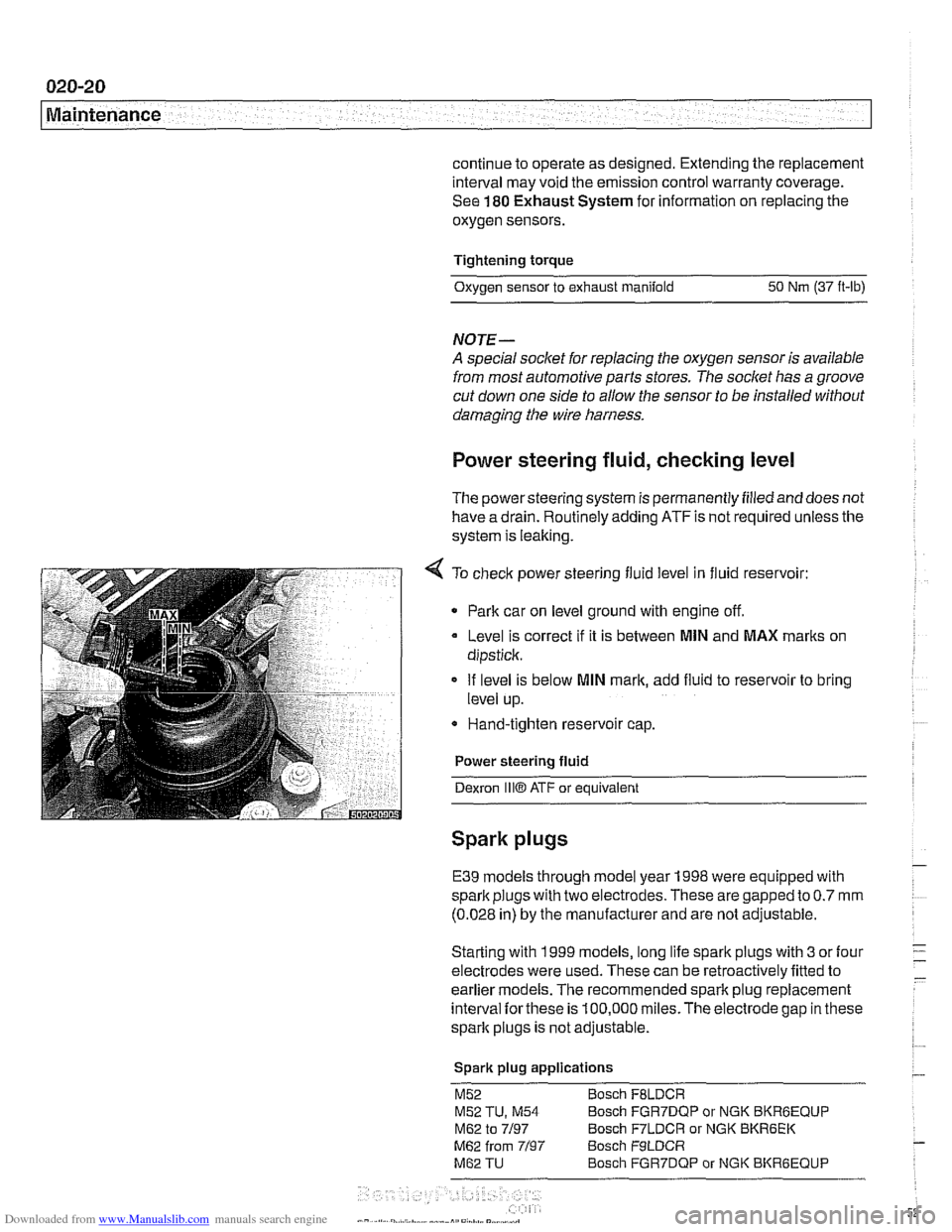
4 To check power steering fluid level in fluid reservoir:
Park car on level ground with engine off.
Level is correct
if it is between MlN and MAX marks on
dipstick.
If level is below
MlN mark, add fluid to reservoir to bring
level up.
* Hand-tighten reservoir cap.
Power steering fluid
Dexron
1iiO ATF or equivalent
Spark plugs
E39 models through model year 1998 were equipped with
spark plugs with two electrodes. These are gapped to
0.7 mm
(0.028 in) by the manufacturer and are not adjustable.
Starting with 1999 models, long life spark plugs with
3 or four
electrodes were used. These can be retroactively fitted to
earlier
models. The recommended spark plug replacement
interval
forthese is 100,000 miles.The electrode gap in these
spark plugs is not adjustable.
Spark plug applications
M52 Bosch FBLDCR
M52 TU, M54 Bosch FGR7DQP or NGK BKRBEQUP
M62 to 7/97 Bosch F7LDCR or NGK BKR6EK
M62 from 7/97 Bosch F9LDCR
M62 TU Bosch FGR7DQP or NGK BKRGEQUP
Page 93 of 1002
Downloaded from www.Manualslib.com manuals search engine
--
-- Engine Removal and installation' -
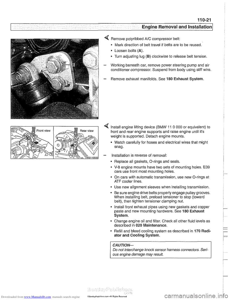
Remove polyribbed A/C compressor belt:
Mark direction of belt travel if belts are to be reused.
Loosen bolts
(A).
Turn adjusting lug (B) clocltwise to release belt tension.
Working beneath car, remove power steering pump and air
conditioner compressor. Suspend from body using stiff wire.
Remove exhaust manifolds. See
180 Exhaust System.
< lnstall engine lifting device (BMW 11 0 000 or equivalent) to
front and rear engine supports and raise engine until it's
weight is supported. Detach engine mounts.
a Watch carefully for hoses and electrical wires that might
snag.
- installation is reverse of removal:
Replace all gaskets, O-rings and seals.
V-8 engine mounts have two sets of mounting holes. E39
cars use front most mounting holes.
* On cars with automatic transmission, use new O-rings at
ATF cooler lines.
Use new alignment sleeves when installing transmission.
Be sure engine drive belts properly engage pulley grooves.
When installing belt, preload tensioner to stop (toward
belt), then tighten tensioner clamping nut.
lnstall front exhaust pipes using new gasltets and copper
paste and new mounting hardware. See
180 Exhaust
System.
Change engine oil and filter. Check all other fluid levels as
described in
020 Maintenance.
Refill and bleed cooling system as described in
170 Radi-
ator and Cooling System.
CAUTION-
Do not interchange knoclc sensor harness connectors. Seri-
ous engine damage may result
Page 442 of 1002
Downloaded from www.Manualslib.com manuals search engine
.. .-
/Fuel lnjeciion
NOJE-
With engine oft disconnect harness connector and checlc
heating element resistance between white wires on the sen-
sor side of harness. If the element is electrically open (no
continuity), replace sensor.
- If oxygen sensor does not produce a fluctuating voltage and
preheater circuit is
OK, replace sensor.
NOJE-
If not already applied, coat oxygen sensor threads w~th anti-
seize compound before installat~on. Do not get the com-
pound on the sensor tip.
Tightening torque Oxygen sensor to exhaust system
55 Nm (41 ft-lb)
Fuel injectors, checking and replacing
The fuel iniectors are switched on and off (oaened and
closed)
by'the ECM. The injectors are connkcted to acom-
mon power source. A ground signal from the ECM is used to
open and close the injectors.
CA U JIOG
Use only a digital multimeter or an LED injector tester when
testing injectors or wiring. Use of an analog
VOM or incan-
descent test light may damaqe the engine controlmodule.
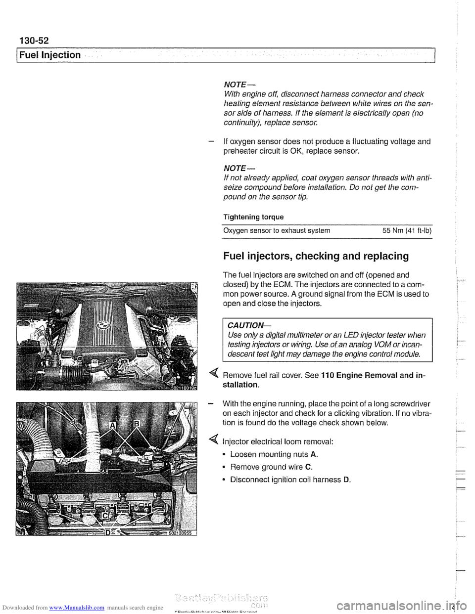
4 Remove fuel rail cover. See 110 Engine Removal and in-
stallation.
With the engine running, place the point of a long screwdriver
on each injector and check for a cliclting vibration.
If no vibra-
tion is found do the voltage
checit shown below.
Injector electrical loom removal:
- Loosen mounting nuts A.
Remove ground wire C.
Disconnect ignition coil harness D
Page 447 of 1002
Downloaded from www.Manualslib.com manuals search engine
Fuel Injection
Intake air temperature
([AT) sensor,
testing and replacing
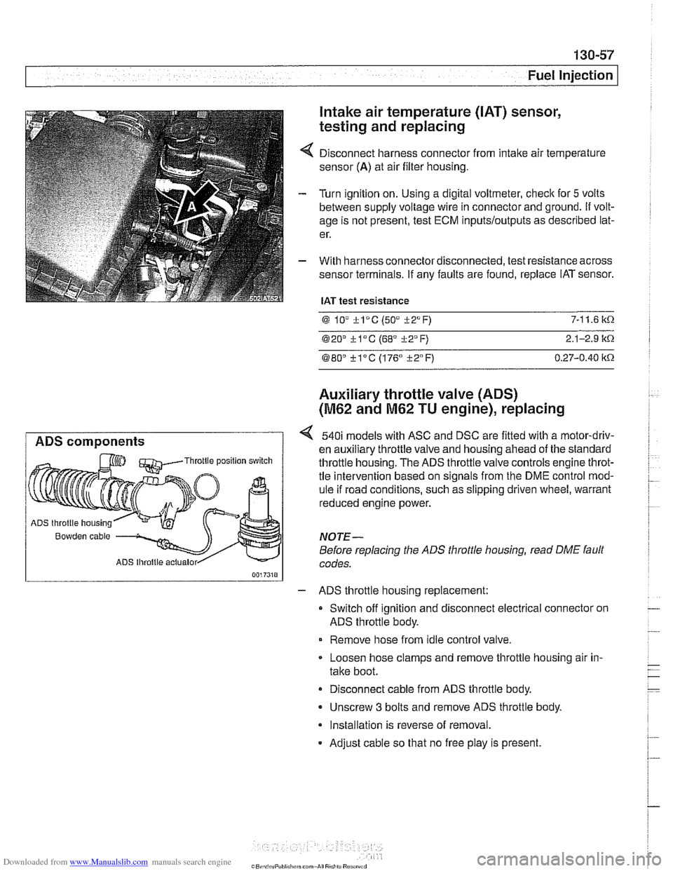
Disconnect harness connector from intake air temperature
sensor
(A) at air filter housing.
Turn ignition on. Using a digital voltmeter, check for
5 volts
between supply voltage wire in connector and ground.
If volt-
age is not present, test ECM
inputs/outputs as described lat-
er.
With harness connector disconnected, test resistance across
sensor terminals. If any faults are found, replace IAT sensor.
IAT test resistance
0 lV *lac (50" i-2°F) 7-1 1.6 k.0.
020' kl°C (68' 322°F) 2.1-2.9 it.0.
080" ?lac (176" i-2°F) 0.27-0.40 itn
Auxiliary throttle valve (ADS)
(M62 and M62 TU engine), replacing
ADS components 540i models with ASC and DSC are fitted with a motor-driv-
en auxiliary throttle valve and housing ahead of the standard Throttle position switch throttle housing. The ADS throttle valve controls engine throt-
tle intervention based on signals from the DME control mod-
ule if road conditions, such as slipping driven wheel, warrant
reduced engine power.
ADS throttle housing
Bowden cable NOTE-
Before replacing the ADS throttle housing, read DME fault
ADS lhroltle actualor codes.
- ADS throttle housing replacement:
Switch off ignition and disconnect electrical connector on
ADS throttle body.
Remove hose from idle control valve.
Loosen hose clamps and remove throttle housing air in-
take boot.
Disconnect cable from ADS throttle body.
- Unscrew 3 bolts and remove ADS throttle body.
Installation is reverse of removal.
- Adjust cable so that no free play is present.
Page 479 of 1002
Downloaded from www.Manualslib.com manuals search engine
.- -
Fuel Tank and Fuel purnpl
Fuel pump power consumption, testing
To achieve accurate test results, the battery voltage at the
fuel pump connector should be
12.6 volts. Charge the battery
as necessary.
A higher than normal power consumption may indicate a
worn fuel pump, which may cause intermittent fuel starvation
due to pump overheating and seizure. The only remedy is
pump replacement.
A lower than normal power consumption
may indicate a blockage. Be sure to check that the return line
and the pump pickup are not obstructed before replacing the
pump.
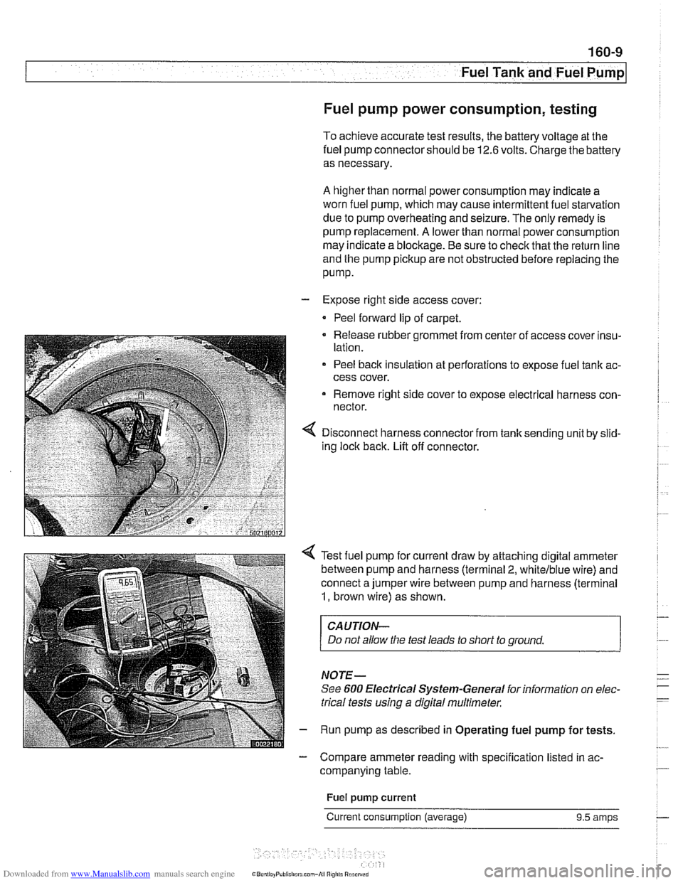
- Expose right side access cover:
Peel forward lip of carpet.
Release rubber grommet from center of access cover insu-
lation.
Peel back insulation at perforations to expose fuel tank ac-
cess cover.
Remove right side cover to expose electrical harness con-
nector.
Disconnect harness connector from tank sending unit by slid-
ing lock back. Lift off connector.
Test fuel pump for current draw by attaching digital ammeter
between pump and harness (terminal
2, whitelblue wire) and
connect a jumper wire between pump and harness (terminal
1, brown wire) as shown.
CAUTION-
Do not allow the test leads to short to ground.
NOTE-
See 600 Electrical Systern-General for information on elec-
trical tests
using a digital multirneter.
Run pump as described in Operating fuel pump for tests.
- Compare ammeter reading with specification listed in ac-
companying table.
Fuel
pump current
Current consumption (average) 9.5 amps
Page 614 of 1002
Downloaded from www.Manualslib.com manuals search engine
-.- .
/ Driveshaft Driveshaft, removing
CAUTION-
. Be sure the wheels are off the ground before removing the
driveshak Set the parl(ing brake before removing the
driveshaft.
Once the driveshaft has been removed, the vehicle can
roll regardless of whether the transmission is in gear or
not.
The driveshaft is mounted to the transmission and final
drive
with self-locliing nuts. These nuts are designed to
be used only once and should be replaced during reas-
sembly.
Remove complete exhaust system. See
180 Exhaust
System.
- Remove exhaust heat shields.
- Support transmission with transmission jack.
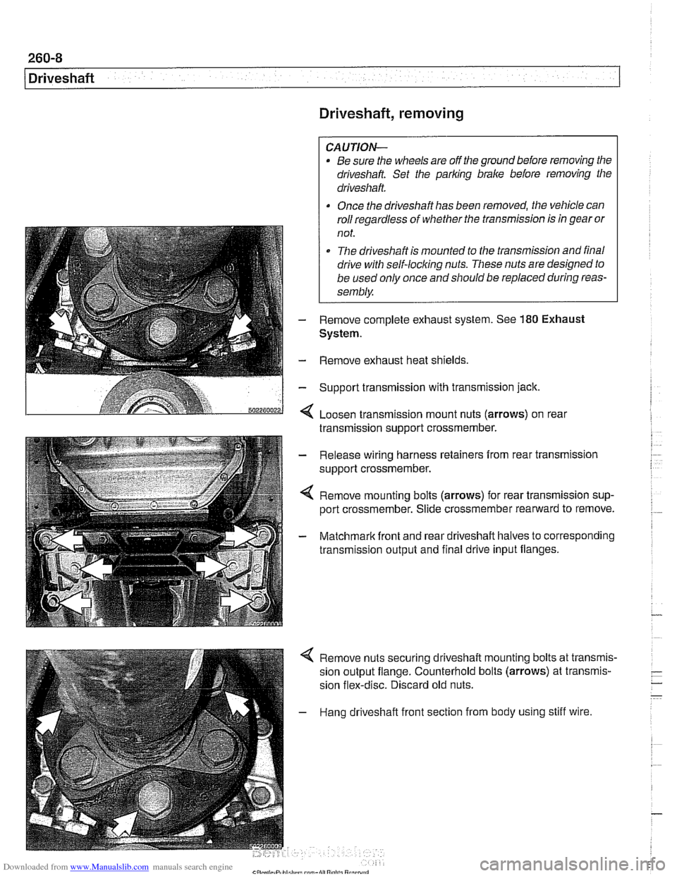
< Loosen transmission mount nuts (arrows) on real
transmission support crossmember.
- Release wiring harness retainers from rear transmission
support crossmember.
< Remove mounting bolts (arrows) for rear transmission sup-
port crossmember. Slide crossmember rearward to remove.
- Matchmark front and rear driveshaft halves to corresponding
transmission output and final drive input flanges.
4 Remove nuts securing driveshaft mounting bolts at transmis-
sion output flange. Counterhold bolts (arrows) at transmis-
sion flex-disc. Discard old nuts.
- Hang driveshaft front section from body using stiff wire.
Page 943 of 1002
Downloaded from www.Manualslib.com manuals search engine
Seat ~eltsl
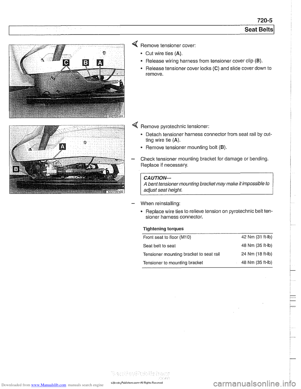
< Remove tensioner cover:
Cut wire ties (A).
Release wiring harness from tensioner cover clip (B).
- Release tensioner cover locks (C) and slide cover down to
remove.
- When reinstalling:
Replace wire ties to relieve tension on pyrotechnic belt
ten-
sioner harness connector.
Tightening torques . -
Front seat to floor (M10) 42 Nm (31 it-lb)
Seat belt to seat 48 Nm (35 It-lb)
Tensioner mounting bracitet
to seat rail 24 Nm (18 it-lb)
Tensioner to mounting bracket 48 Nm (35 it-lb)