Steering column BMW 528i 2000 E39 Workshop Manual
[x] Cancel search | Manufacturer: BMW, Model Year: 2000, Model line: 528i, Model: BMW 528i 2000 E39Pages: 1002
Page 331 of 1002
Downloaded from www.Manualslib.com manuals search engine
Lubrication system/
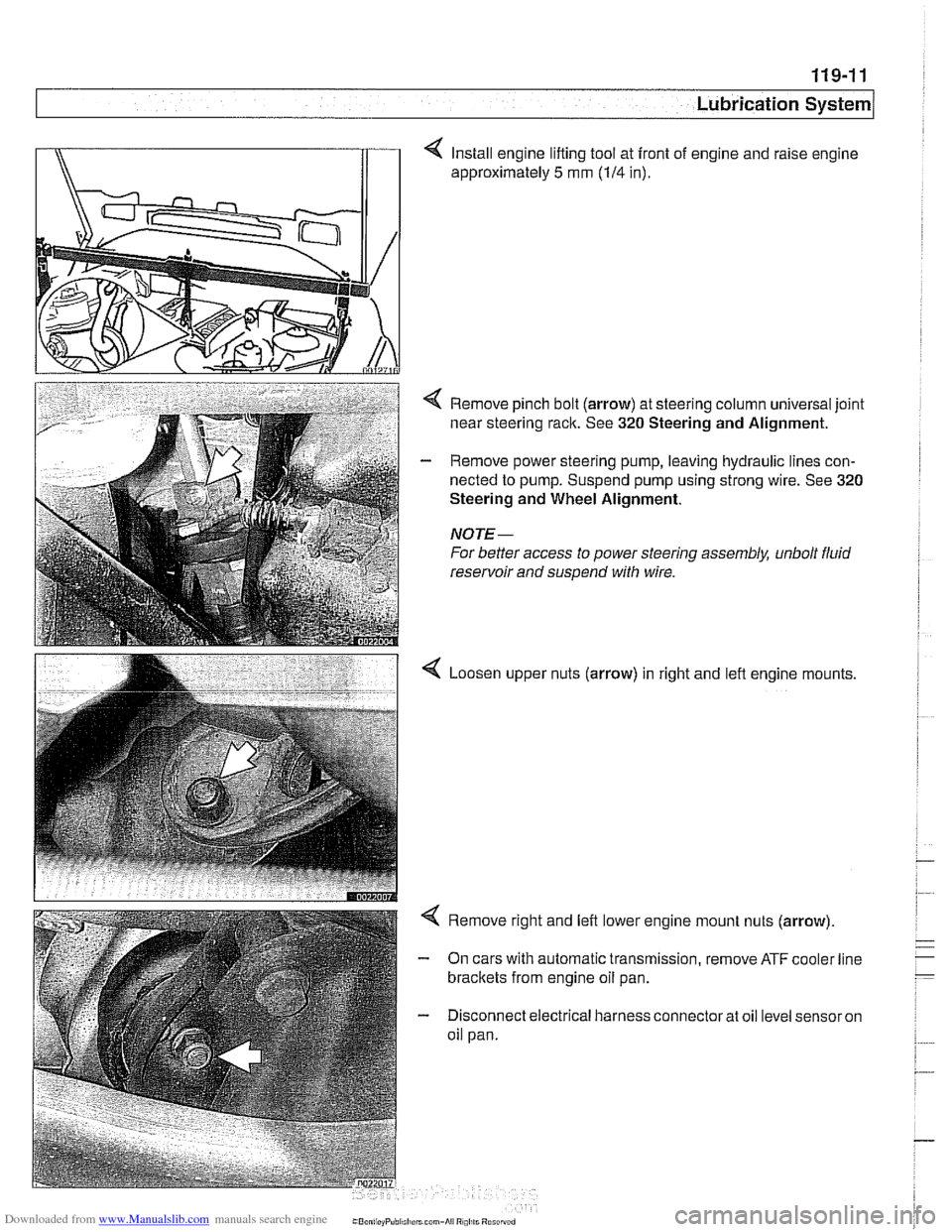
4 Install engine lifting tool at front of engine and raise engine
approximately
5 mm (114 in).
< Remove pinch bolt (arrow) at steering column universal joint
near steering rack. See
320 Steering and Alignment.
- Remove power steering pump, leaving hydraulic lines con-
nected to pump. Suspend pump using strong wire. See
320
Steering and Wheel Alignment.
NOTE-
For better access to power steering assembly, unbolt fluid
reservoir and suspend with wire.
Loosen upper nuts (arrow) in right and lefl engine mounts,
< Remove right and left lower engine mount nuts (arrow)
- On cars with automatic transmission, remove ATF cooler line
brackets from engine oil pan.
- Disconnect electrical harness connector at oil level sensor on
oil pan.
Page 338 of 1002
Downloaded from www.Manualslib.com manuals search engine
119-18
I Lubrication System
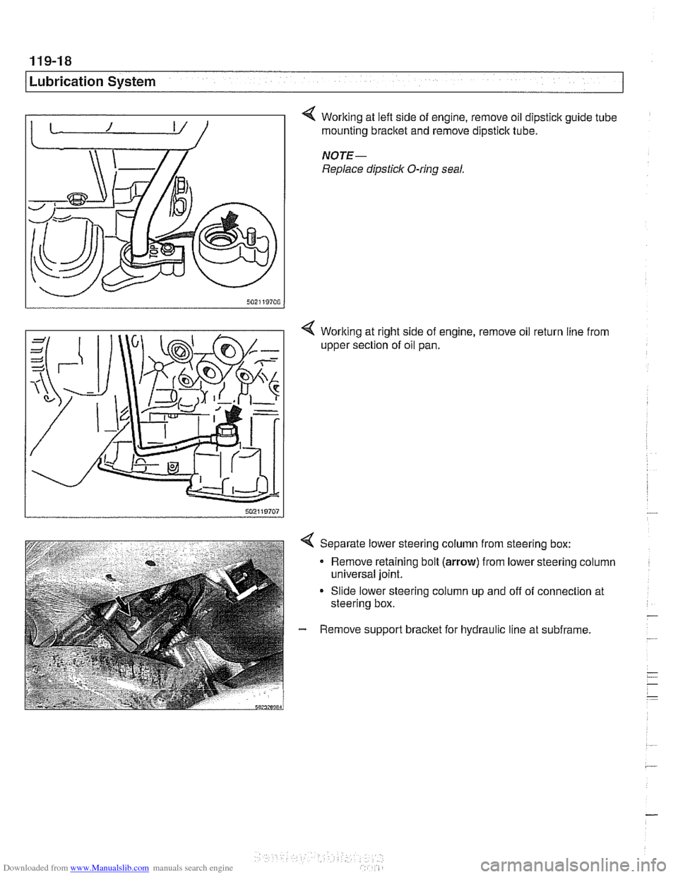
4 Working at lefl side of engine, remove oil dipstick guide tube 1 mounting bracket and remove dipstick tube.
NOTE-
Replace dipstick O-ring seal.
< Working at right side of engine, remove oil return line from
upper section of oil pan.
4 Separate lower steering column from steering box:
Remove retaining bolt
(arrow) from lower steering column
universal joint.
Slide lower steering column up and off of connection at
steering box.
- Remove support bracket for hydraulic line at subframe.
Page 340 of 1002
Downloaded from www.Manualslib.com manuals search engine
Lubr~cat~on System r- -
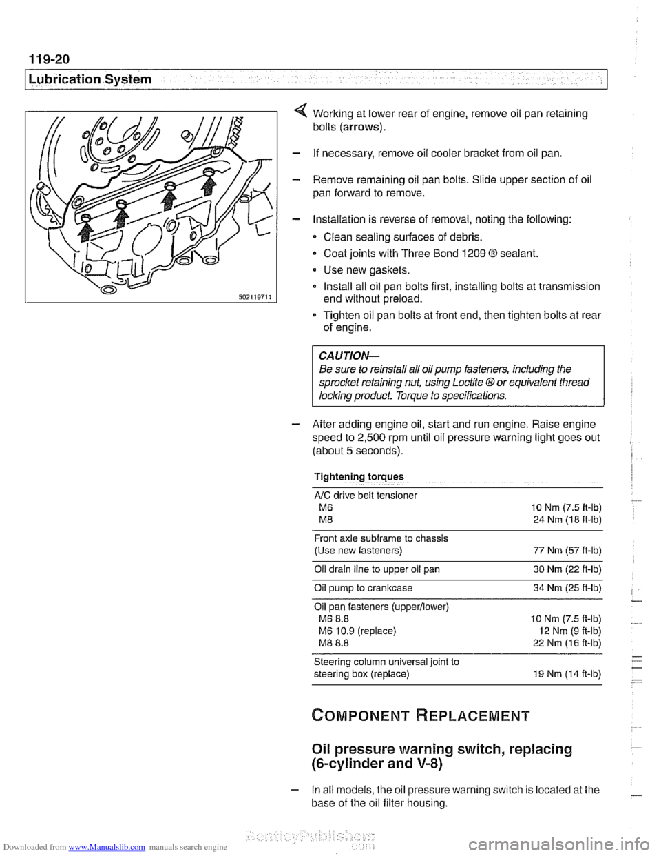
Working at lower rear of engine, remove oil pan retaining
bolts
(arrows).
- If necessary, remove oil cooler bracket from oil pan.
- Remove remaining oil pan bolts. Slide upper section of oil
pan forward to remove.
- Installation is reverse of removal, noting the following:
Clean sealing surfaces of debris.
- Coat joints with Three Bond 1209 O sealant.
Use new gaskets.
Install all oil pan bolts first, installing bolts at transmission
end without preload.
Tighten oil pan bolts at front end, then tighten bolts at rear
of engine.
Be sure to reinstall all oil
pump fasteners, including the
sprocl
speed to
2,500 rpm until oil pressure warning light goes out
(about
5 seconds).
Tightening torques
AIC drive belt tensloner
M6 10 Nm (7.5 it-lb)
M8 24 Nm (18 ft-lb)
Front axle
subframe to chassis
(Use new fasteners) 77 Nm (57 ft-lb)
Oil drain
line to upper oil pan 30 Nm (22 ft-lb)
Oil pump to crankcase 34 Nm (25 ft-lb)
Oil pan fasteners
(upperllower)
M6 8.8 10 Nm (7.5 ft-lb)
M6 10.9 (replace)
I2 Nm (9 ft-lb)
M8 8.8 22 Nm (16 ft-lb)
Steering column universal joint to
steering box (replace) 19 Nm (14 ft-lb)
Oil pressure warning switch, replacing
(&cylinder and V-8)
- In all models, the oil pressure warning switch is located at the
base of the oil filter housing.
Page 659 of 1002
Downloaded from www.Manualslib.com manuals search engine
1 320 Steering and Wheel Alignment
General ........................... .32 0.2
Special tools
........................ .32 0.2
Steering system
..................... .32 0.4
Steering system variations
............. .32 0.5
Steering system warnings and cautions
... .32 0.6
Steering Wheel .................... .32 0.7
Steering wheel. removal and installation
.. .32 0.7
Steering Column ................. .32 0.1 0
Steering column components .......... .32 0.10
Steering column trim, removing
and replacing
...................... .32 0.10
lgnition switch ring antenna (EWS).
removing and installing
............... .32 0.1 1
lgnition lock cylinder.
removing and installing
............... .32 0-1 1
Steering column lock. removing
and installing
....................... .32 0.12
lgnition
interloclc cable. removing and installing
(models with automatic transmission)
... .32 0.13
Interlock cable. adjusting
(models with automatic transmission)
... .32 0.14
Steering column. removing and installing
. .32 0.14
Steering column adjustment motors.
removing and installing
............... .32 0.16
Power Steering Pump ............. .32 0.17
Power steering pump. removing
and installing
....................... .32 0.1 7
Power steering system.
bleeding and filling
.................. .32 0.18
Rack and Pinion Steering
(6-cylinder models)
............... 320-19
Rack and pinion steering components
(6-cylinder models)
.................. 320-1 9
Steering rack. removing and installing
.... 320-19
Steering
rack boot. replacing ........... 320-22
Tie rod (outer). replacing
.............. 320-22
Tie rod (inner). replacing
.............. 320-23
Steering Gearbox (V-8 models) .... 320-24
Steering gearbox system components
. .
(V-8 models) ....................... 320-24
Steering gearbox, removing and installing 320-25
Pitman arm. removing and installing ..... 320-28
Pitman arm. adjusting ................ 320-29
Steering idler arm. removing
and installing
....................... 320-30
Idler arm bushing. replacing ........... 320-31
Center tie rod. replacing
.............. 320-32
Wheel Alignment .................. 320-33
Camber
........................... 320-33
Caster
............................ 320-33
Front toe and toe difference angle
....... 320-34
Reartoe ........................... 320-34
Preparing for alignment
............... 320-35
Alignment specifications tables
......... 320-35
Page 660 of 1002
Downloaded from www.Manualslib.com manuals search engine
I Steering and Wheel Alignment
This repair group covers steering wheel and column removal
and steering system service, including wheel alignment infor-
mation.
NOTE-
Ignition loclc cylinder replacement is covered in this sec-
tion.
a For information on steering column mounted switches, in-
cluding the ignition switch, see
612 Switches.
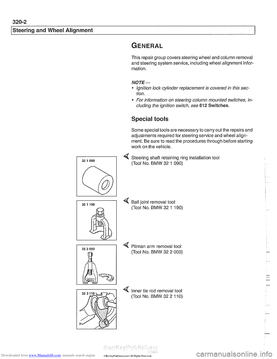
Special tools
Some special tools are necessary to carry out the repairs and
adjustments required for steering service and wheel align-
ment. Be sure to read the procedures through before starting
work on the vehicle.
4 Steering shafl retaining ring installation tool
(Tool No. BMW 32
1 090)
4 Bail joint removal tool
(Tool No. BMW 32
1 190)
4 Pitman arm removal tool
(Tool No. BMW 32 2
000)
4 Inner tie rod removal tool
(Tool No. BMW 32 2
110)
Page 661 of 1002
Downloaded from www.Manualslib.com manuals search engine
320-3
Steering and Wheel ~li~nmentl
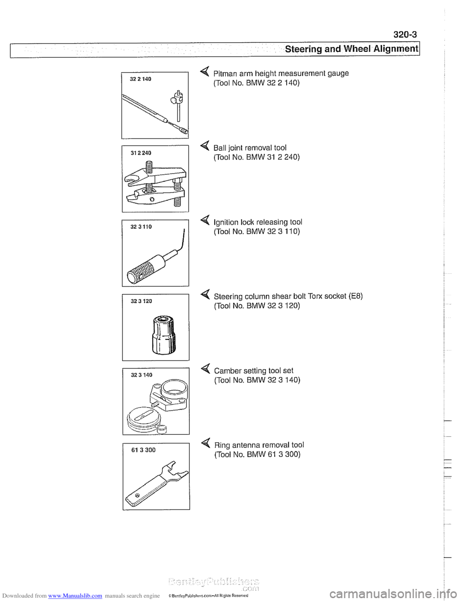
4 Pitman arm height measurement gauge
/I (Tool NO. BMW 32 2 140)
-
4 Ball joint removal tool
(Tool No. BMW 31 2 240)
4 Ignition lock releasing tool
(Tool No. BMW 32 3
11 0)
4 Steering column shear bolt Toot socket (E8)
(Tool No. BMW 32 3 120)
4 Camber setting tool set
(Tool No. BMW 32 3 140)
4 Ring antenna removal tool
(Tool No. BMW
61 3 300)
Page 662 of 1002
Downloaded from www.Manualslib.com manuals search engine
I Steerina and Wheel Alianment
Steering
system
Two types of steering gear are used in the E39 series models.
6-cylinder
(5251, 528i and 530i) models are equipped with
rack and pinion steering. The steering rack is mounted to
an aluminum subframe.
V-8
(540i) models are equipped with a recirculating ball
and nut steering gearbox mounted to a steel subframe.
At low speeds, maximum power assist is provided to ease
parking and city driving. At high speeds, assist is reduced to
ensure stability. The power steering system varies assist
based on engine speed.
Power boost for the steering is provided by an engine-driven
hydraulic pump. A hydraulic control valve is used to control
boost pressure.
The steering wheel connects to the steering gear via an ad-
justable steering column which incorporates a rubber cou-
pling ("guibo") to dampen vibration and noise.
Power steering fluid is supplied from the fluid
reservoir to the
pump and to the steering gear via rubberlmetal hoses.
The return line from the steering gear to the
reservoir loops
into the airstream in front of the radiator and connects to the
steering fluid cooler. The fluid cooler is attached to a cassette
which also includes cooling coils for engine oil, transmission
fluid and AIC condenser.
The steering gear requires no maintenance other than align-
ment and periodic inspection for worn components. Inspect
rubber rack boots
(rack and pinion system) and tie-rod end
boots periodically for tears or damage. Replace
if necessary.
-
NOTE-
The airbag system is traditionally referred to as Supplemen-
tal Restraint System (SRS). The
BMW versfon of SRS used
m the E39 models is known as the Multiple Restraint System - (MRS). - -
Page 667 of 1002
Downloaded from www.Manualslib.com manuals search engine
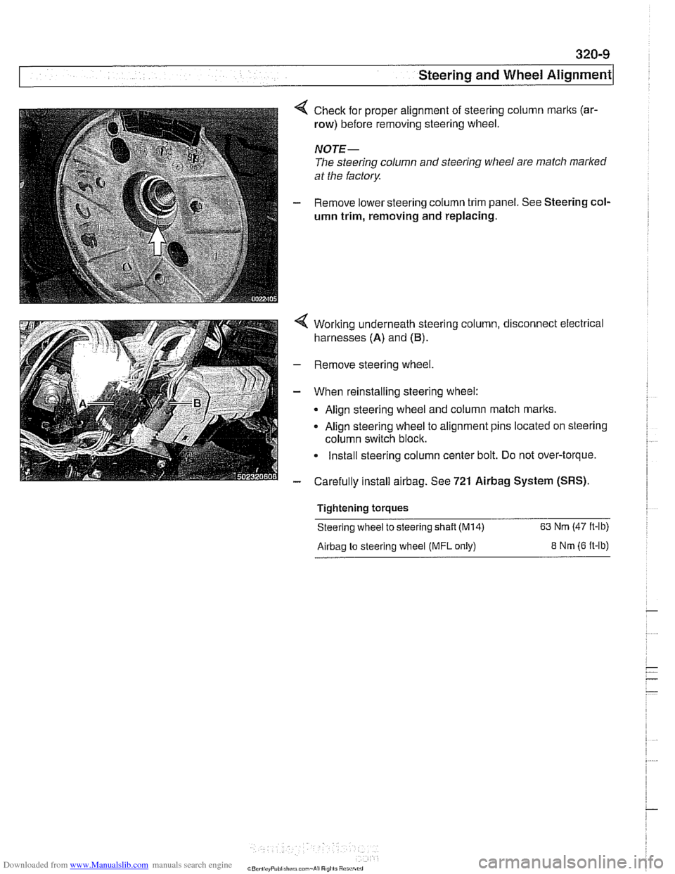
Check for proper alignment of steering column marks (ar-
row) before removing steering wheel.
NOTE-
The steering column and steering wheel are match marked
at the factory
Remove lower steering column trim panel. See Steering col-
umn trim, removing
and replacing.
Working underneath steering column, disconnect electrical
harnesses (A) and
(B).
Remove steering wheel.
When reinstalling steering wheel:
Align steering wheel and column match
marks.
Align steering wheel to alignment pins located on steering
column switch block.
Install steering column center bolt. Do not over-torque.
Carefully install
airbag. See 721 Airbag System (SRS).
Tightening torques
Steering wheel to steering
shaft (M14) 63 Nm (47 ft-lb)
Airbag to steering wheel (MFL only) 8 Nm (6 ft-lb)
Page 668 of 1002
Downloaded from www.Manualslib.com manuals search engine
320-1 0
Steering and Wheel Alignment
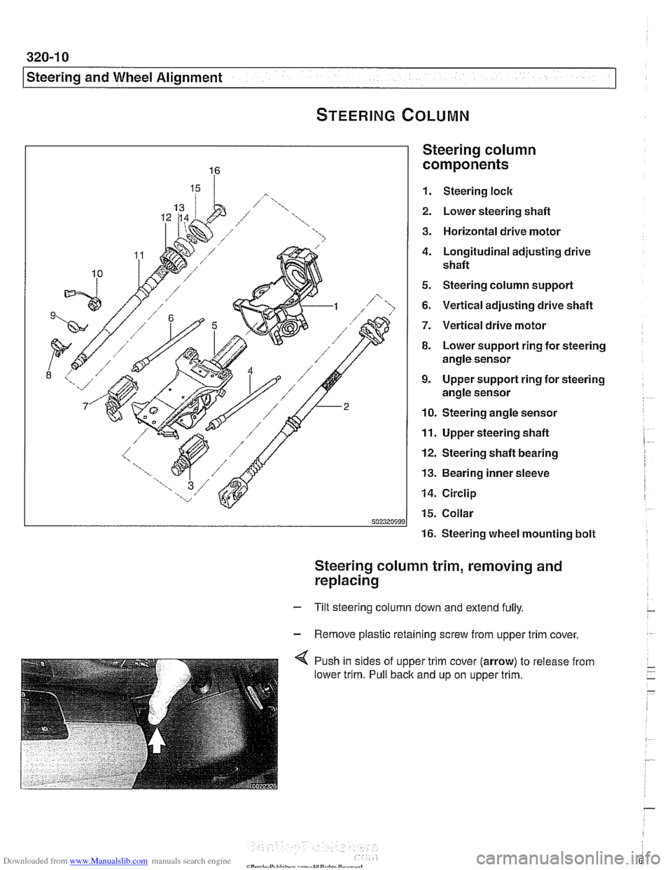
Steering column
components
1. Steering lock
2. Lower steering shafl
3. Horizontal drive motor
4. Longitudinal adjusting drive
shafl
5. Steering column support
6. Vertical adjusting drive shafl
7. Vertical drive motor
8. Lower support ring for steering
angle sensor
9. Upper support ring for steering
angle sensor
10. Steering angle sensor
11. Upper steering shafl
12. Steering shafl bearing
13. Bearing inner sleeve
14. Circlip
15. Collar
16. Steering wheel mounting bolt
Steering column trim, removing and
replacing
- Tilt steering column down and extend fully.
- Remove plastic retaining screw from upper trim cover,
4 Push in sides of upper trim cover (arrow) to release from
lower trim. Pull back and up on upper trim.
Page 669 of 1002
Downloaded from www.Manualslib.com manuals search engine
Steering and Wheel ~li~nrnentl
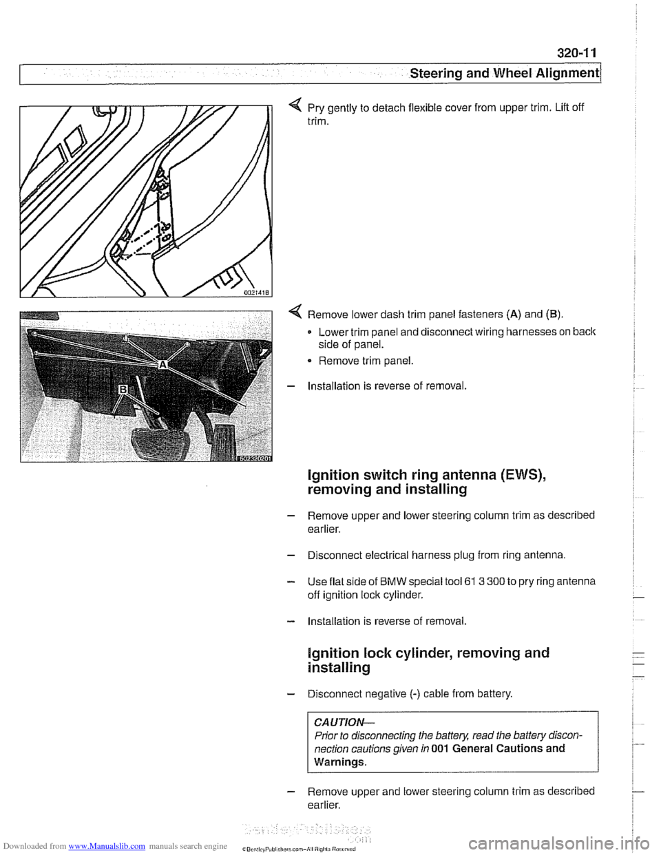
q Pry gently to detach flexible cover from upper trim. Lift off
trim.
< Remove lower dash trim panel fasteners (A) and (B).
Lower trim panel and disconnect wiring harnesses on back
side of panel.
Remove trim panel.
- Installation is reverse of removal.
Ignition switch ring antenna (EWS),
removing and installing
- Remove upper and lower steering column trim as described
earlier.
- Disconnect electrical harness plug from ring antenna.
- Use flat side of BMW special tool 61 3 300 to pry ring antenna
off ignition lock cylinder.
- Installation is reverse of removal.
lgnition lock cylinder, removing and
installing
- Disconnect negative (-) cable from battery.
CAUTION-
Prior to disconnecting the battery, read the battery discon-
nection cautions given
in 001 General Cautions and
Warnings.
- Remove upper and lower steering column trim as described
earlier.