oil separator BMW 528i 2000 E39 Workshop Manual
[x] Cancel search | Manufacturer: BMW, Model Year: 2000, Model line: 528i, Model: BMW 528i 2000 E39Pages: 1002
Page 81 of 1002
Downloaded from www.Manualslib.com manuals search engine
Engine Removal and lnstallationl
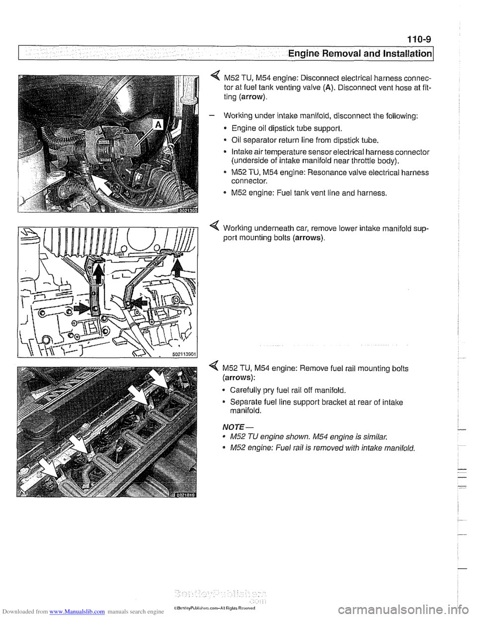
M52 TU, M54 engine: Disconnect electrical harness connec-
tor at fuel tank venting valve
(A). Disconnect vent hose at fit-
ting (arrow).
- Working under intake manifold, disconnect the following:
Engine oil dipstick tube support.
Oil separator return line from
dipsticlc tube.
Intake air temperature sensorelectrical harness connector
(underside of intake manifold near throttle body).
M52 TU, M54 engine: Resonance valve electrical harness
connector.
M52 engine: Fuel tank vent line and harness.
< Working underneath car, remove lower intalte manifold sup-
port mounting bolts (arrows).
4 M52 TU. M54 engine: Remove fuel rail mounting bolts
(arrows):
Carefully pry fuel rail off manifold.
Separate fuel line support bracket at rear of intake
manifold.
NOTE-
* M52 TU engine shown. M54 engine is similar.
M52 engine: Fuel rail is removed with intalte manifold.
Page 105 of 1002
Downloaded from www.Manualslib.com manuals search engine
..
Cylinder Head Removal and Installation 1
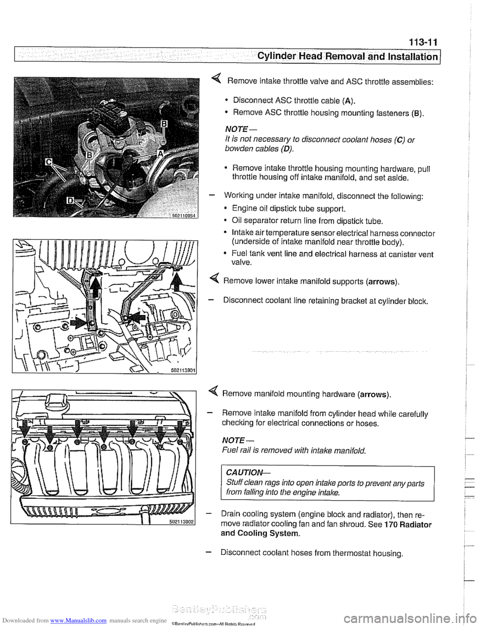
< Remove intake throttle valve and ASC throttle assemblies:
Disconnect ASC throttle cable
(A).
- Remove ASC throttle housing mounting fasteners (B).
NOTE-
It is not necessary to disconnect coolant hoses (C) 01
bowden cables (D).
Remove intake throttle housing mounting hardware, pull
throttle housing off
intake manifold, and set aside.
- Working under intake manifold, disconnect the following:
Engine oil dipstick tube support.
Oil separator return line from dipstick tube.
Intake air temperature sensor electrical harness connector
(underside of intake manifold near throttle body).
* Fuel tank vent line and electrical harness at canister vent
valve.
Remove lower intake manifold supports (arrows).
- Disconnect coolant line retaining bracket at cylinder block.
4 Remove manifold mounting hardware (arrows).
- Remove intake manifold from cylinder head while carefully
checking for electrical connections or hoses.
NOTE-
Fuel rail is removed with intake manifold,
CAUTIOI\C
Stuff clean rags into open intake ports to prevent any parts
from falling into
Nie engine intake.
- Drain cooling system (engine block and radiator), then re-
move radiator cooling fan and fan shroud. See
170 Radiator
and Cooling System.
- Disconnect coolant hoses from thermostat housing.
Page 120 of 1002
Downloaded from www.Manualslib.com manuals search engine
. - --
j Cylinder Head Removal and Installation
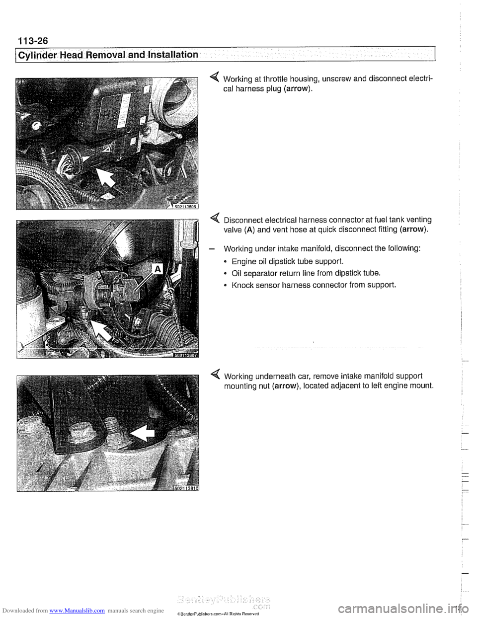
4 Working at throttle housing, unscrew and disconnect electri-
cal harness plug
(arrow).
4 Disconnect electrical harness connector at fuel tank venting
valve
(A) and vent hose at quick disconnect fitting (arrow).
- Working under intake manifold, disconnect the following:
Engine oil dipstick tube support.
Oil separator return line from dipstick tube.
Knock sensor harness connector from support.
4 Working underneath car, remove intake manifold support
mounting nut
(arrow), located adjacent to left engine mount.
Page 159 of 1002
Downloaded from www.Manualslib.com manuals search engine
1 13-65
Cylinder Head Removal and Installation /
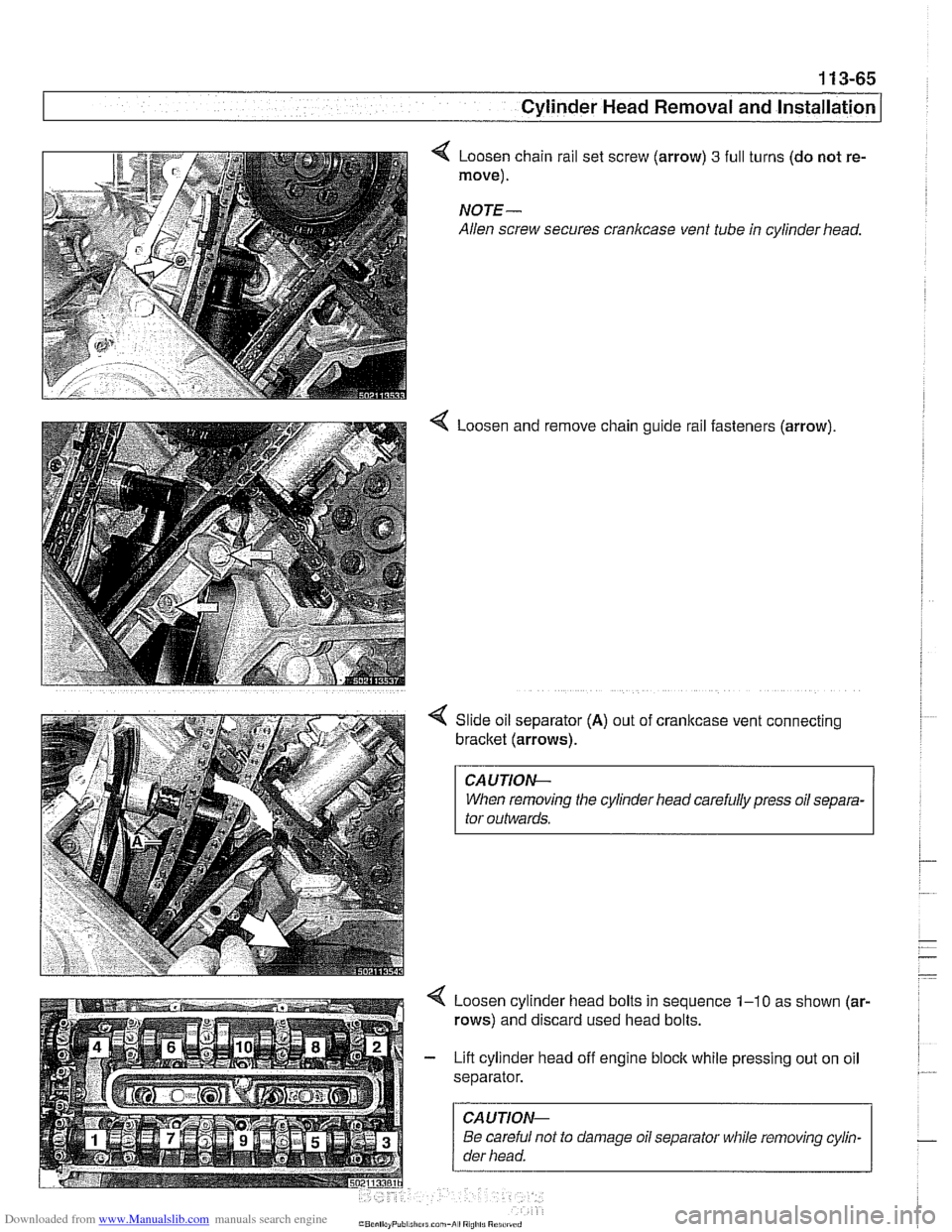
Loosen chain rail set screw (arrow) 3 full
move).
NOTE-
Allen screw secures crankcase vent tube
4 Loosen and turns
(do not re-
in cylinder head.
remove chain guide rail fasteners (arrow).
Slide oil separator
(A) out of cranltcase vent connecting
bracket (arrows).
CAUTIOI\C
When removing the cylinder head carefully press oil separa-
tor outwards.
Loosen cylinder head bolts in sequence
1-10 as shown (ar-
rows) and discard used head bolts.
Lift cylinder head off engine block while pressing out on oil
separator.
CAUTIOI\C
Be careful not to damage oil separator while removing cylin-
der head.
Page 160 of 1002
Downloaded from www.Manualslib.com manuals search engine
. .- --
I Cylinder Head Removal and Installation
- Evaluate cylinder head as described in 116 Cylinder head
and valvetrain.
Left cylinder head, installing, M62 engine
- Clean cylinder head and block sealing surfaces of gasket
debris, making sure no debris drops into coolant or oil pas-
sages.
- Clean cylinder head bolt holes and check condition of
threads.
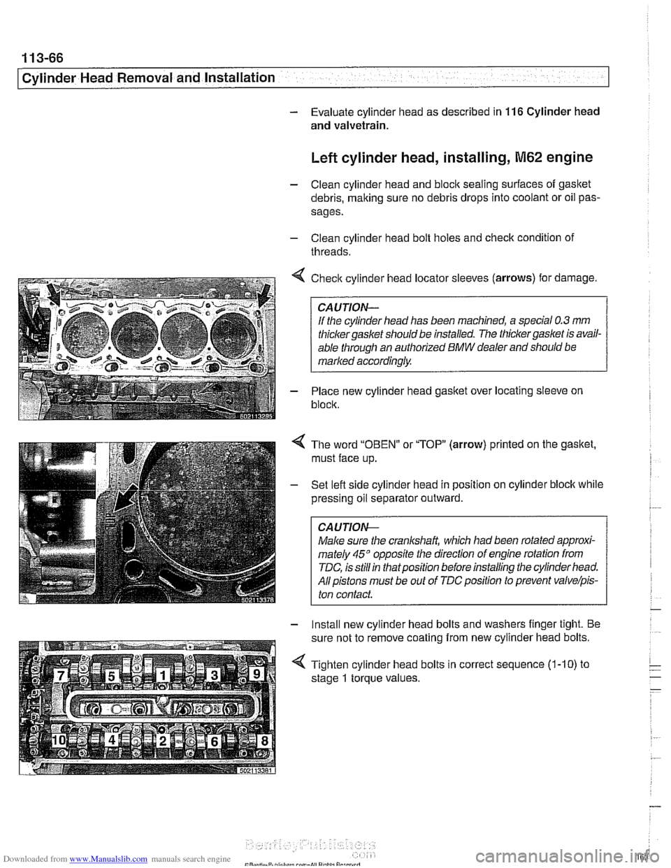
< Check cylinder head locator sleeves (arrows) for damage.
If the cylinder head has been machined, a special
0.3 mm
thicker gasket should be installed. The thicker gasket is avail-
able through an authorized
BMW dealer and should be
marked accordingly.
- Place new cylinder head gasket over locating sleeve on
block.
The word
"OBEN" or "TOP" (arrow) printed on the gasket,
must face up.
Set lefl side cylinder head in position on cylinder block while
pressing oil separator outward.
CAUJION-
Male sure the crankshaft, which had been rotated approxi-
mately
45" opposite the direction of engine rotation from
TDC, is still in thatposition before installing the cylinder head.
All pistons must be out of
TDCposition to prevent valvelpis-
ton contact.
- Install new cylinder head bolts and washers finger tight. Be
sure not to remove coating from new cylinder head bolts.
4 Tighten cylinder head bolts in correct sequence (1-10) to
stage
1 torque values.
Page 161 of 1002
Downloaded from www.Manualslib.com manuals search engine
1 13-67
Cylinder Head Removal and lnstaKI --
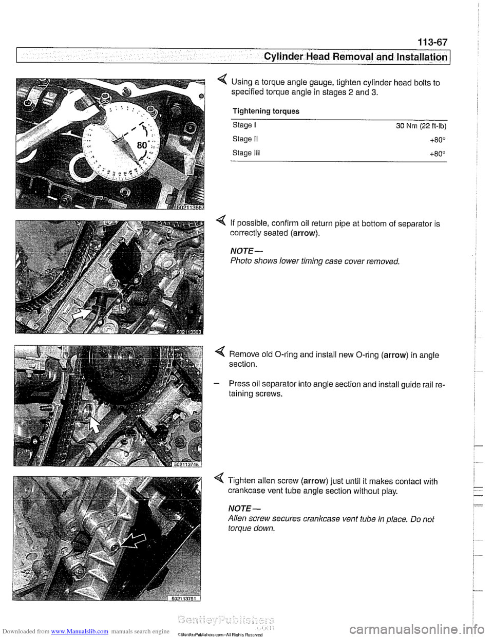
< Using a torque angle gauge, tighten cylinder head bolts to
specified torque angle in stages
2 and 3.
Tightening torques
Stage I 30 Nrn (22 ft-lb)
Stage II +80°
Stage Ill +80°
4 If possible, confirm oil return pipe at bottom of separator is
correctly seated
(arrow).
NOTE-
Photo shows lower timing case cover removed.
< Remove old O-ring and install new O-ring (arrow) in angle
section.
- Press oil separator into angle section and install guide rail re-
taining screws.
4 Tighten allen screw (arrow) just until it makes contact with
crankcase vent tube angle section without play.
NOTE-
Allen screw secures crankcase vent tube in place. Do not
torque down.
Page 330 of 1002
Downloaded from www.Manualslib.com manuals search engine
11 9-1 0
Lubrication System
Oil pan, removing and installing
(6-cylinder)
The engine oil pan removal procedure requires that the en-
gine be supported from the top and the front suspension
sub-
frame be lowered.
- Raise car and place securely on jack stands.
Make sure the car is stable and well supported at all times.
Use a professional automotive
lift orjackstands designed for
- Remove splash shield from under engine.
- Drain engine oil as described in 020 Maintenance.
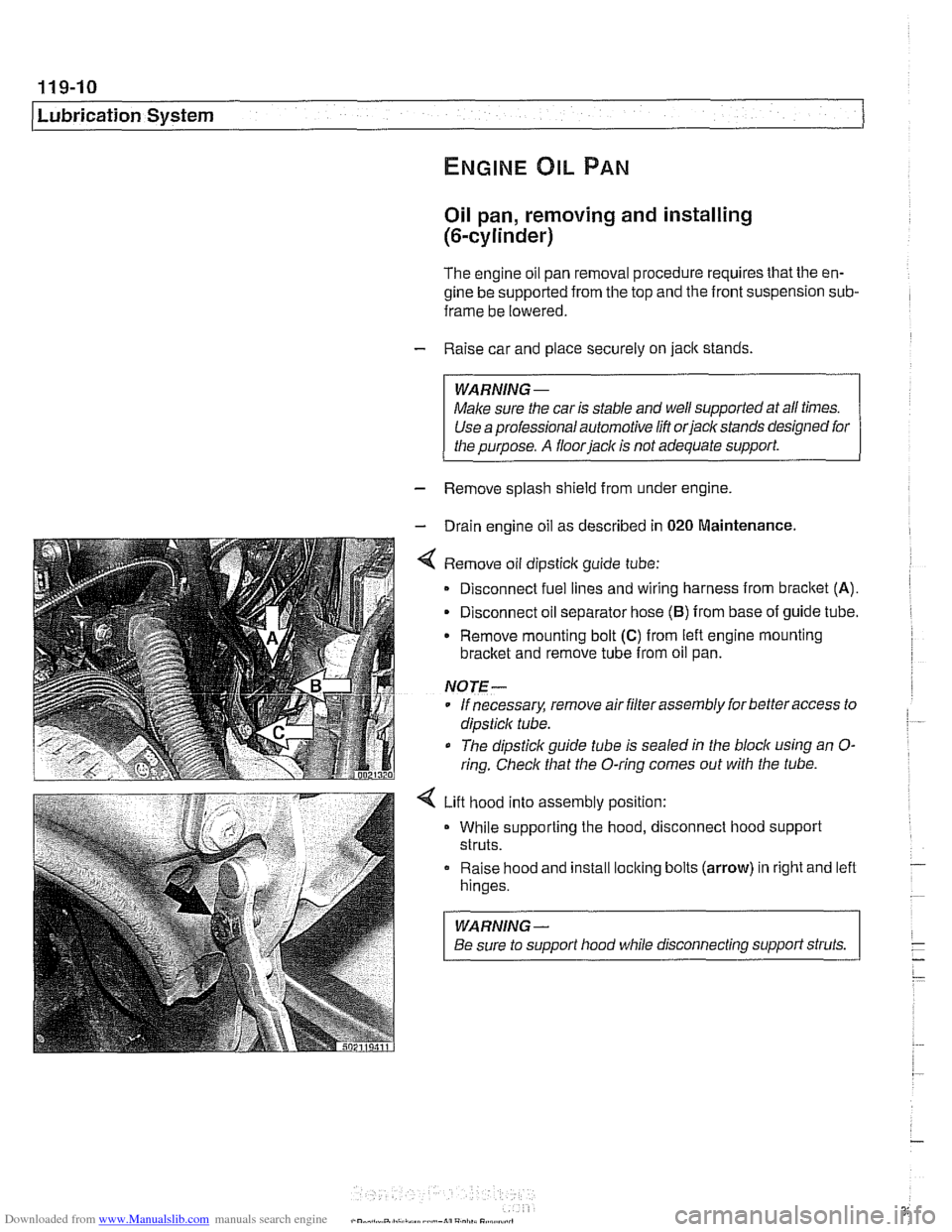
4 Remove oil dipsticlc guide tube:
Disconnect fuel lines and wiring harness from
bracket (A).
- Disconnect oil separator hose (B) from base of guide tube.
Remove mounting bolt
(C) from left engine mounting
bracket and remove tube from oil pan.
NOTE-
* If necessary, remove air filter assembly for better access to
dipsticlc tube.
The dipstick guide tube is sealed in the block using an
O-
ring. Check that the O-ring comes out with the tube.
4 Lift hood into assembly position:
While supporting the hood, disconnect hood support
struts.
Raise hood and install
loclting bolts (arrow) in right and left
hinges.
WARNING-
Be sure to support hood while disconnecting support struts.