piston valves BMW 528i 2000 E39 Workshop Manual
[x] Cancel search | Manufacturer: BMW, Model Year: 2000, Model line: 528i, Model: BMW 528i 2000 E39Pages: 1002
Page 101 of 1002
Downloaded from www.Manualslib.com manuals search engine
. .- . --
Lr -- - - - -- Cylinder Head Removal and Installation I -
- Release pressure at compression gauge valve, then remove
gauge from spark plug hole. Repeat test for each cylinder
and compare results with values given in Table a.
Table a. Compression testing specifications
Minimum compression
6-cylinder
10-1 1 bar (142-156 psi)
V-8 12-14 bar (174-203 psi)
Maximum difference between
cylinders (all engines)
0.5 bar (7 psi)
- Compression readings may be interpreted as follows:
Low compression indicates a poorly sealed combustion
chamber.
0 Relatively even pressures that are below specification nor-
mally indicate worn piston rings
andlor cylinder walls.
Erratic values tend to indicate valve leakage.
Dramatic differences between cylinders are often a sign of
a failed head
gasket, burned valve, or broken piston ring.
- If readings are within specifications, reinstall spark plugs and
ignition coils.
NOTE-
Used spark plugs should be reinstalled in the same cylinder
from which they were removed.
Tightening torque Spark plug to cylinder head 25 Nm
(18 ft-lb)
lanition coils to cylinder head 10 Nm (7.5 ft-lb)
- Remainder of installation is reverse of removal. Be sure to re-
install all wires disconnected during test, especially ground
wires at coils and cylinder head cover (where applicable).
Wet compression test
To further help analyze the source of poorcompression,awet
compression test is the next step.
- Repeat compression test, this time squirt a teaspoon of oil
into each cylinder. The oil will temporarily help seal between
piston rings and cylinder wall, practically eliminating leakage
past rings for a short time.
- If this test yields a higher reading than "dry" compression
test, there is probably leakage between piston rings and
cylinder walls, due either to wear or to broken piston rings.
- Little or no change in compression reading indicates other
leakage, probably from valves.
Page 110 of 1002
Downloaded from www.Manualslib.com manuals search engine
113-16
Cylinder Head Removal and Installation
- Remove secondary timing chain and sprockets:
Remove mounting nuts from front of intake camshaft
sprocket. Remove and label shim.
CAUTION-
Hold the camshaft stationary (at hex on camshaft) when loos-
ening or tightening sprocket mounting fasteners.
Remove mounting nuts from front of exhaust camshaft
sprocket and remove and label thrust washer.
NOTE-
Where applicable, make note of thrust washerpositions. The
thicker
(0.4 mm) washer is mounted outermost.
- Remove secondary sprockets together with camshaft tim-
ing chain from front of camshafts.
CAUTION-
The camshafts must be locledin the TDCposition using the
special service tool as described earlier: The arrows on the
sprockets should not be used to accurately set the engine to
TDC. The tool holds the camshafts parallel to each other and
NOTE-
Do not remove the sprocl
to
Iceep the sproclefs timed to each other:
CAUTIOI\C
The crankshaft must not be allowed to rotate once the cam-
shaft timing chain is removed. The pistons can
contact the
valves.
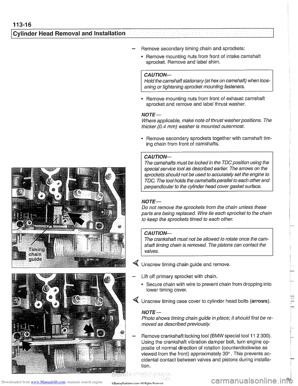
Unscrew timing chain guide and remove.
Lift off primary sprocket with chain.
Secure chain with wire to prevent chain from dropping into
lower timing cover.
Unscrew timing case cover to cylinder head bolts (arrows).
NOTE-
Photo shows timing chain guide in place; it should first be re-
moved as described previously.
Remove crankshaft locking tool
(BMW special tool 11 2 300).
Using the crankshaft vibration damper bolt, turn engine op-
posite of normal direction of rotation (counterclocltwise as
viewed from the front) approximately 30". This prevents ac-
cidental contact between valves and pistons during installa-
tion.
Page 111 of 1002
Downloaded from www.Manualslib.com manuals search engine
Cylinder Head Removal -- and lnstallati~i
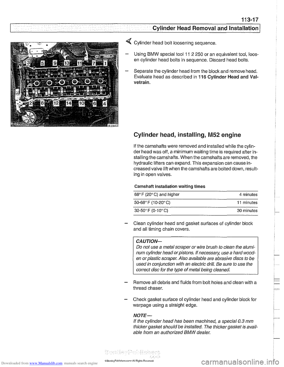
4 Cylinder head bolt loosening sequence.
- Using BMW special tool 11 2 250 or an equivalent tool, loos-
en cylinder head bolts in sequence. Discard head bolts.
- Separate the cylinder head from the block and remove head.
Evaluate head as described in
116 Cylinder Head and Val-
vetrain.
Cylinder head, installing, M52 engine
If the camshafts were removed and installed while the cylin-
der head was off, a minimum waiting time is required after in-
stalling the camshafts. When the camshafts are removed, the
hydraulic lifters can expand. This expansion can cause in-
creased valve lift when the camshafts are bolted down, result-
ing in open valves.
Camshaft installation waiting times
68" F (20" C) and higher 4 minutes
50.68' F (1 0-20" C) 11 minutes
32-50' F (0-1 0" C) 30 minutes
- Clean cylinder head and gasket surfaces of cylinder block
and all timing chain covers.
CAUTION-
Do not use a metal scraper or wire brush to clean the alumi-
num cylinder head orpistons. If necessary, use a hard wood-
en orplastic scraper. Also available are abrasive discs to be
used in conjunction with an electric drill. Be sure to use the
correct disc for the type of metal being cleaned.
- Remove all debris and fluids from bolt holes and clean with a
thread chaser.
- Check gasket surface of cylinder head and cylinder block for
warpage using a straight edge.
NOTE-
If the cylinder head has been machined, a special 0.3 mm
thicker gasket should be installed. The thicker
gasket is avail-
able from an authorized
BMW dealer.
Page 114 of 1002
Downloaded from www.Manualslib.com manuals search engine
--
Cylinder Head Removal and Installation
NOTE-
BMW special tool 11 4 220 is an adjustable primary chain
tensioner and simulates the function of the hydraulic
tensioner.
- Check that elongated holes in primary sprocket are now cen-
tered to bolt holes in camshaft and chain is free of slack. If
not, reposition sprocket to chain and reinstall.
- lnstall secondary timing chain guide and secondary chain
tensioner. Tighten mounting bolts (tensioner remains locked
down for now using
BMW special tool 11 3 292).
- Install cylinder identification trigger plate to front of intake
camshaft with studs.
- Install spacer to front of intake camshaft.
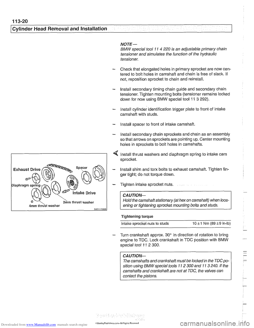
- Install secondary chain sprockets and chain as an assembly
so that arrows on sprockets are pointing up. Center mounting
holes in sprockets to bolt holes in camshafts.
4 lnstall thrust washers and diaphragm spring to intake cam
sprocket.
I 2hm thrust washer I
- Install shim and torx bolts to exhaust camshaft. Tighten fin-
ger tight; do not torque down.
- Tighten intake sprocket nuts.
CA UTIOG
Hold the camshaft stationary (at hex on camshaft) when loos-
enino or tiahtenino sorocket mounting bolts and studs.
Tightening torque
Intake s~rocket nuts to studs 10 +l Nm (89 +9 in-lb)
- Turn crankshaft approx. 30" in direction of rotation to bring
engine to TDC. Lock crankshaft in TDC position with BMW
special tool
11 2 300.
CAUTION-
The camshafts andcranlshaft must be lockedin the TDCpo-
sition using BMW special tools 11 2 300 and 11 3 240. If the
camshafts and cranl(shaft are not at TDC, the valves can
contact the pistons.
Page 147 of 1002
Downloaded from www.Manualslib.com manuals search engine
Cylinder Head Removal and Installation /
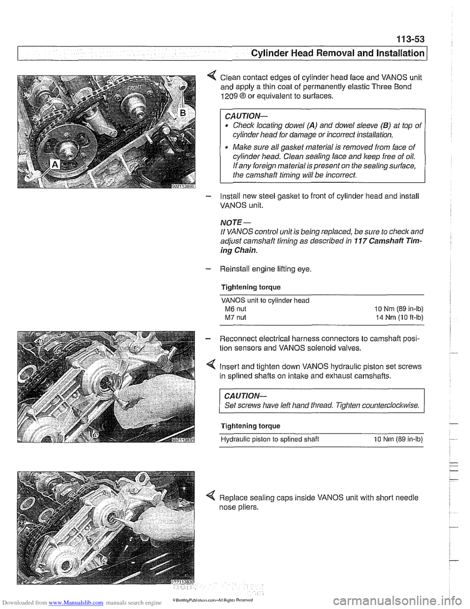
< Clean contact edges of cylinder head face and VANOS unit
and apply a thin coat of permanently elastic Three Bond
1209 8 or equivalent to suriaces.
CAUTION-
Check locating dowel (A) and dowel sleeve (B) at top of
cylinder head for damage or incorrect installation.
Make sure all gasket material is removed from face of
cylinder head. Clean sealing face and keep free of oil.
If any foreign material is present on the sealing surface,
the camshaft timing will be incorrect.
- Install new steel gasket to front of cylinder head and install
VANOS unit.
NOTE -
If VANOS control unit is being replaced, be sure to check and
adjust camshaft timing as described in
11 7 Camshaft Tim-
ing Chain.
- Reinstall engine lifting eye.
Tightening torque
VANOS unit to cylinder head
M6 nut
M7 nut
lo Nm (89 in-lb)
14 Nrn (10 it-lb)
- Reconnect electrical harness connectors to camshaft posi-
tion sensors and VANOS solenoid valves.
4 Insert and tighten down VANOS hydraulic piston set screws
in splined shafts on
intake and exhaust camshafts.
CAUJION-
Set screws have left hand tliread. Tighten counterclockwise.
Tightening torque
Hydraulic piston
to splined shaft 10 Nm (89 in-lb)
< Replace sealing caps inside VANOS unit with short needle
nose pliers.
Page 156 of 1002
Downloaded from www.Manualslib.com manuals search engine
. .- --
[Cylinder ~ead Removal and Installation
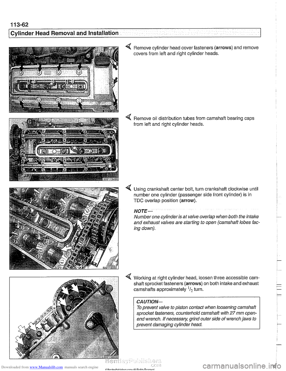
4 Remove cylinder head cover fasteners (arrows) and remove
covers from left and right cylinder heads.
4 Remove oil distribution tubes from camshaft bearing caps
from left and right cylinder heads.
4 Using crankshaft center bolt, turn crankshaft clockwise until
number one cylinder (passenger side front cylinder) is in
TDC overlap position (arrow).
NO JE -
Number one cylinder is at valve overlap when both the intake
and exhaust valves are starting to open (camshaft lobes fac-
ing down).
4 Working at right cylinder head, loosen three accessible cam-
shaft sprocltet fasteners (arrows) on both intake and exhaust
camshafts approximately
'I2 turn.
To prevent valve to piston contact when loosening camshaft
sprocket fasteners, counterhold camshaft with
27 mm open-
end wrench.
If necessary, grind outerside of wrench jaws to
prevent damaging cylinder head.
Page 250 of 1002
Downloaded from www.Manualslib.com manuals search engine
I Camshaft Timing Chain
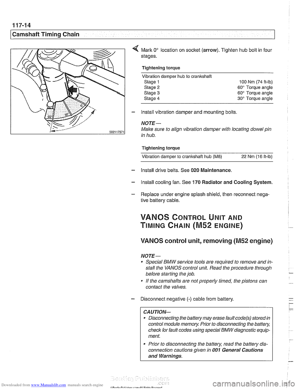
Mark 0" location on socket (arrow). Tighten hub bolt in four
stages.
Tightening torque Vibration damper
hub to cranlrshaft
Stage 1 100 Nm (74 it-lb)
Stage
2 60" Torque angle
Stage
3 60" Torque angle
Stage
4 30" Torque angle
- install vibration damper and mounting bolts
NOTE-
Male sure to align vibration damper with locating dowel pin
in hub.
Tightening torque Vibration damper to
cranltshait hub (ME) 22 Nm (16 ft-lb)
- Install drive belts. See 020 Maintenance.
- Install cooling fan. See 170 Radiator and Cooling System.
- Replace under engine splash shield, then reconnect nega-
tive battery cable.
!/ANBS CONTROL UNIT AND
TIMING CHAIN (M52 ENGINE)
VANOS control unit, removing (M52 engine)
NOTE-
Special BMW service tools are required to remove and in-
stall the
VANOS control unit. Read the procedure through
before starting the job.
If the camshafts are notproperly timed, the pistons can
contact the valves.
- Disconnect negative (-) cable from battery.
CAUTION-
Disconnecting the battery may erase fault code(s) stored in
control module memory. Prior to disconnecting the
battev,
check for fault codes using special BMW diagnostic equip-
ment.
* Prior to disconnecting the battery, read the battery dis-
connection cautions given in
001 General Cautions
and Warnings.
Page 258 of 1002
Downloaded from www.Manualslib.com manuals search engine
Camshaft Timing Chain
VANOS timing, checking and adjusting
(M52 engine)
NOTE-
* Special BMW service tools are required to remove and in-
stall the VANOS control unit. Read the procedure through
before starting the job.
If the camshafts are not properly timed, the pistons can
contact the valves.
- Disconnect negative (-) cable from battery.
CAUTIOG Disconnecting the battery may erase
faultcode(s) storedin
control module memory. Prior to disconnecting the battery,
checlc for fault codes using special BMW diagnostic equip-
ment.
Prior to disconnecting the battery, read the battery dis-
connection cautions given in
001 General Cautions
and Warnings.
- Remove viscous clutch cooling fan. See 170 Radiator and
Cooling
System.
CAUTIOG The radiator cooling fan nut
(32 mm wrench) has left-hand
threads.
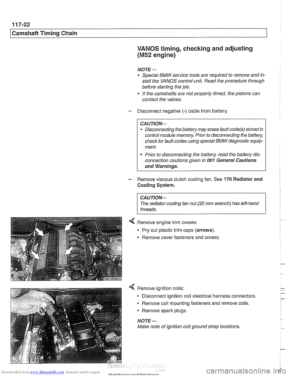
4 Remove ignition coils:
Disconnect ignition coil electrical harness connectors.
Remove coil mounting fasteners and remove coils.
Remove
spark plugs.
NOTE-
Make note of ignition coil ground strap locations.
Page 262 of 1002
Downloaded from www.Manualslib.com manuals search engine
Camshaft Timing Chain Timing chains, removing
(M52 engine)
Camshaft timing chain removal on M52 engines requires en-
gine oil pan removal.
Special
BMW sewice tools are needed for timing chain re-
moval and installation procedures. The special tools assure
propertiming of thevalvetrain. Precise marks to
setthe timing
on the camshafts are not provided for reassembly. Read the
procedures through before beginning the job.
NOTE-
If the camshafts are not properly timed, the pistons can con-
tact the valves.
- Remove VANOS control unit. See VANOS control unit, re-
moving (M52 engine).
- Remove radiator cooling fan and shroud. See 170 Radiator
and Cooling System.
- Drain cooling system. See 170 Radiator and Cooling Sys-
tem.
- Remove coolant hoses from thermostat housing and remove
thermostat housing from front of cylinder head.
- Loosen bolts for coolant pump pulley.
- Remove drive belts for alternator and AIC compressor. See
020 Maintenance.
- Remove coolant pump pulley.
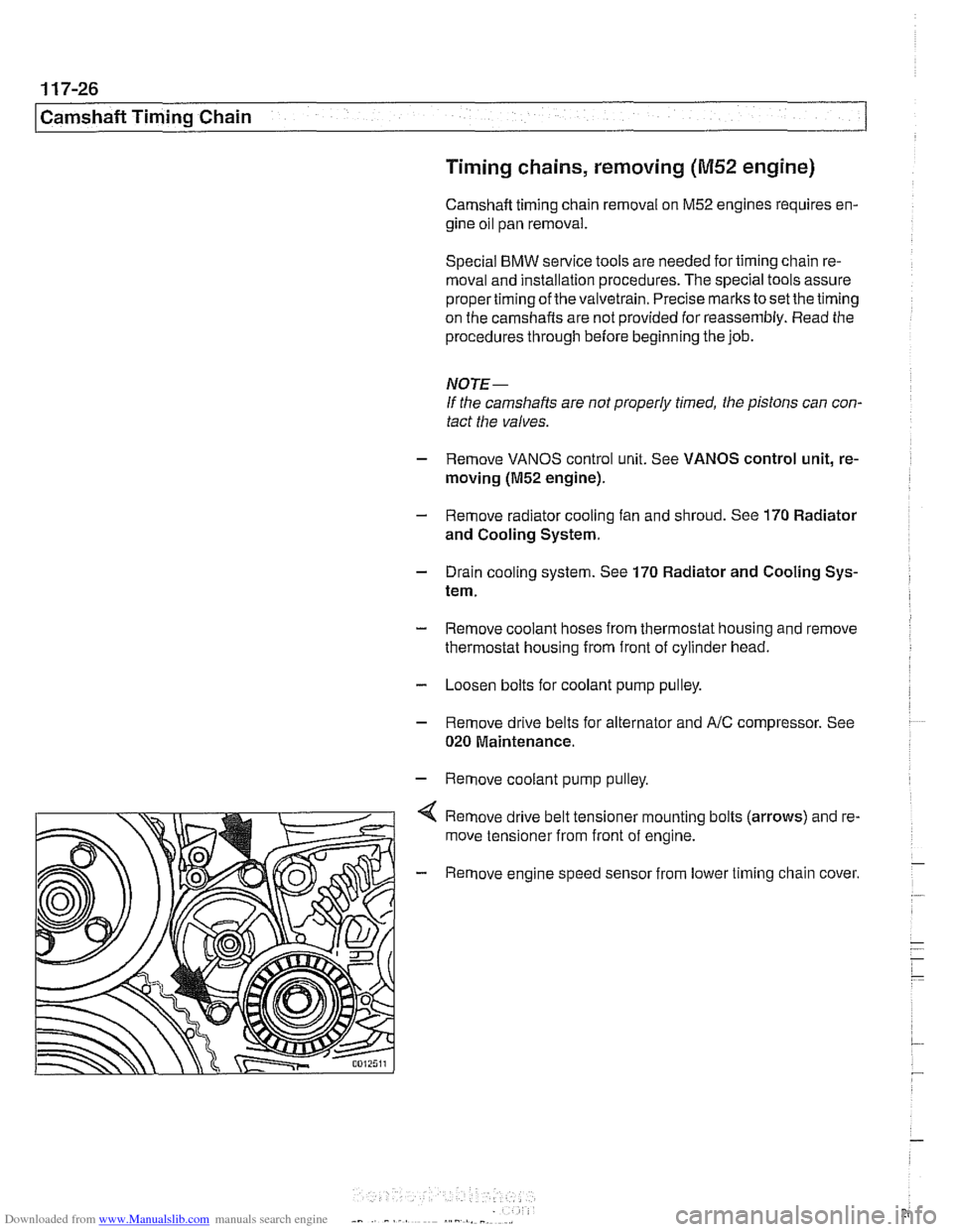
Remove drive belt tensioner mounting bolts (arrows) and re-
move tensioner from front of engine.
- Remove engine speed sensor from lower timing chain cover.
Page 270 of 1002
Downloaded from www.Manualslib.com manuals search engine
1 17-34
1 Camshaft Timing Chain
DOUBLE VAMOS SYSTEM
(M52 TU AND M54 ENGINES)
Double VANOS system function
The M52TU and M54 6-cylinder engines are equipped with a
Double VANOS system that varies intake and exhaust cam-
shaft timing.
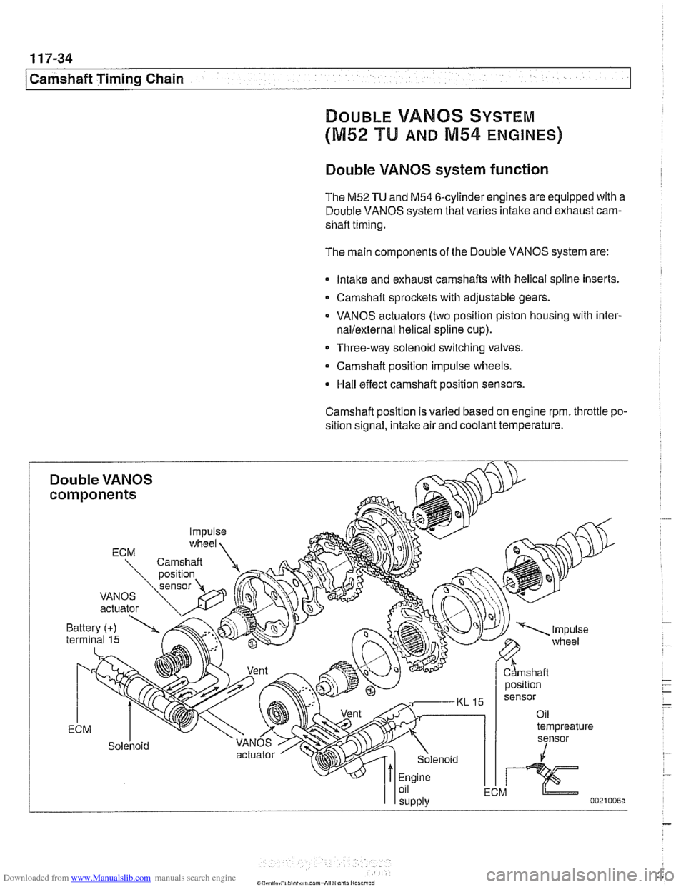
The main components of the Double VANOS system are:
lntalte and exhaust camshafts with helical spline inserts.
Camshaft sprockets with adjustable gears.
VANOS actuators (two position piston housing with
inter-
nallexternal helical spline cup).
Three-way solenoid switching valves.
Camshaft position impulse wheels.
Hall effect camshaft position sensors.
Camshaft position
IS varied based on engine rpm, throttle po-
sition signal, intake air and coolant temperature.