throttle position sensor BMW 528i 2000 E39 Workshop Manual
[x] Cancel search | Manufacturer: BMW, Model Year: 2000, Model line: 528i, Model: BMW 528i 2000 E39Pages: 1002
Page 77 of 1002
Downloaded from www.Manualslib.com manuals search engine
Engine Removal and lnstallationl
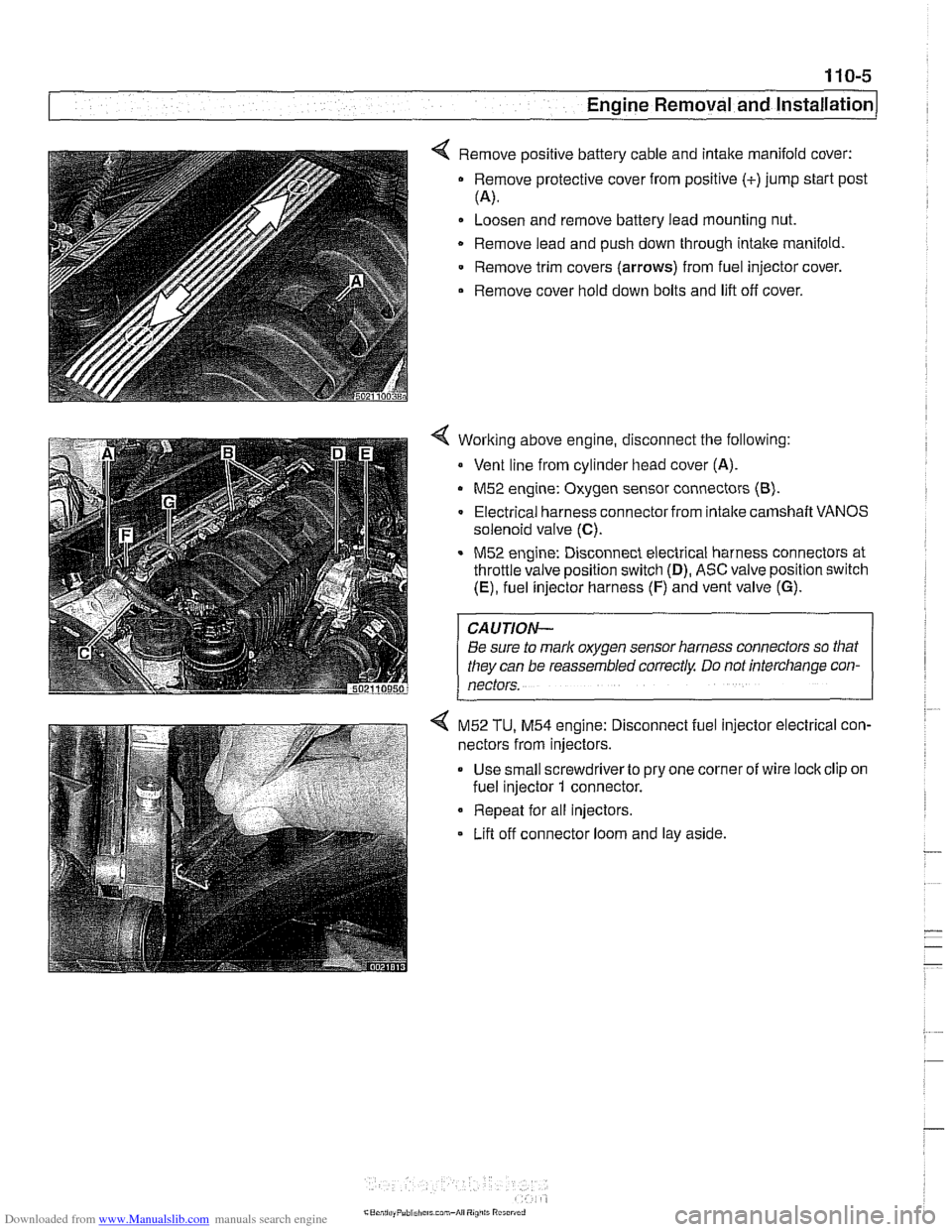
< Remove positive battery cable and intake manifold cover:
Remove protective cover from positive (+)jump start post
(4.
Loosen and remove battery lead mounting nut.
Remove lead and push down through intake manifold
Remove trim covers
(arrows) from fuel injector cover.
Remove cover hold down bolts and lift off cover.
Working above engine, disconnect the following:
Vent line from cylinder head cover (A).
M52 engine: Oxygen sensor connectors (8).
Electrical harness connector from intalte camshaft VANOS
solenoid valve
(C).
M52 engine: Disconnect electrical harness connectors at
throttle valve position switch
(D), ASC valve position switch
(E), fuel injector harness (F) and vent valve (G).
CAUTION-
Be sure to mark oxygen sensor harness connectors so that
they can be reassembled correctly Do not interchange con-
nectors.
4 M52 TU, M54 engine: Disconnect fuel injector electrical con-
nectors from injectors.
Use small screwdriverto pry one corner of wire lock clip on
fuel injector
1 connector.
Repeat for all injectors.
Lifl off connector loom and lay aside.
Page 91 of 1002
Downloaded from www.Manualslib.com manuals search engine
110-19
Engine Removal and Installation
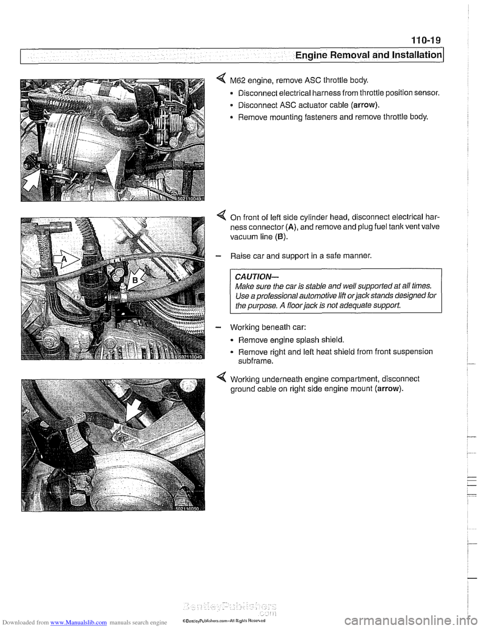
M62 engine, remove ASC throttle body.
Disconnect electrical harness from throttle position sensor.
- Disconnect ASC actuator cable (arrow).
. Remove mounting fasteners and remove throttle body.
On front of left side cylinder head, disconnect electrical har-
ness connector
(A), and remove and plug fuel tank vent valve
vacuum line
(0).
Raise car and support in a safe manner.
CAUTION-
Male sure the car is stable and well supported at aN times.
Use a professional automotive
lifi orjackstands designed for
I the ouroose. A floor jack is not adequate support.
Working beneath car:
- Remove engine splash shield.
Remove right and left heat shield from front suspension
subframe.
Working underneath engine compartment, disconnect
ground cable on right side engine mount
(arrow).
Page 104 of 1002
Downloaded from www.Manualslib.com manuals search engine
113-10
Cylinder Head Removal and Installation
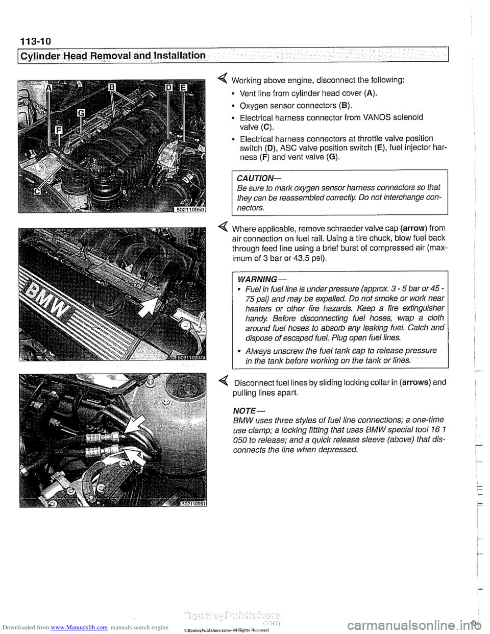
4 Working above engine, disconnect the following:
Vent line from cylinder head cover
(A).
. Oxygen sensor connectors (B).
Electrical harness connector from VANOS solenoid
valve
(C).
Electrical harness connectors at throttle valve position
switch
(D), ASC valve position switch (E), fuel injector har-
ness
(F) and vent valve (G).
CAUTION-
Be sure to mark oxygen sensor harness connectors so that
they can be reassembled correctly Do not interchange con-
nectors.
4 Where applicable, remove schraeder valve cap (arrow) from
air connection on fuel rail. Using a tire chuck, blow fuel back
through feed line using a brief burst of compressed air (max-
imum of
3 bar or 43.5 psi).
WARNING-
. Fuel in fuel line is underpressure (approx. 3 - 5 bar or 45 -
75 psi) and may be expelled. Do not smoke or work near
heaters or other fire hazards. Keep a fire extinguisher
handy Before disconnecting fuel hoses, wrap a cloth
around fuel hoses to absorb any leaking fuel. Catch and
dispose of escaped fuel. Plug open fuel lines.
- Always unscrew the fuel rank cap ro release pressure
;n the tank before working on the tank or lines.
Disconnect fuel lines by sliding locking collar in (arrows) and
pulling lines apart.
NOTE-
BMW uses three styles of fuel line connections; a one-time
use
clamp; a locking fitting that uses BMWspecial tool 16 1
050 to release; and a quick release sleeve (above) that dis-
connects the line when depressed.
Page 153 of 1002
Downloaded from www.Manualslib.com manuals search engine
- .-
.. Cylinder Head Removal and Installation I -
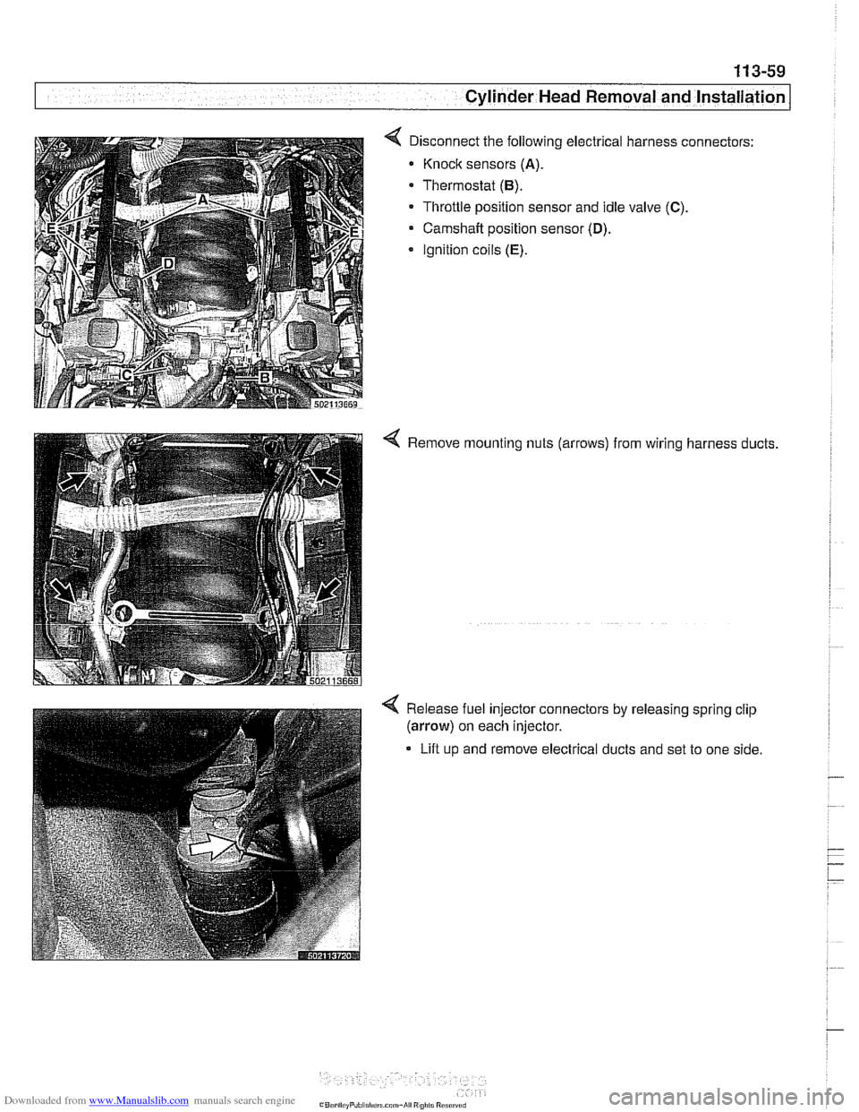
< Disconnect the following electrical harness connectors:
Knock sensors
(A).
Thermostat (6).
Throttle position sensor and idle valve (C).
Camshaft position sensor (D).
Ignition coils (E).
< Remove mounting nuts (arrows) from wiring harness ducts.
4 Release fuel injector connectors by releasing spring clip
(arrow) on each injector.
Lift up and remove electrical ducts and set to one side
Page 216 of 1002
Downloaded from www.Manualslib.com manuals search engine
-. .
Cylinder Head and Valvetrain -- v . -- --- --
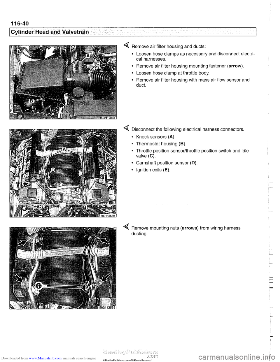
4 Remove air filter housing and ducts:
Loosen hose clamps as necessary and disconnect electri-
cal harnesses.
- Remove air filter housing mounting fastener (arrow).
Loosen hose clamp at throttle body.
Remove air filter housing with mass air flow sensor and
duct.
Disconnect the following electrical harness connectors.
Knoclc sensors (A).
Thermostat housing (B).
Throttle position sensor/throttle position switch and idle
valve
(C).
Camshaft position sensor (D).
* Ignition coils (E).
Remove mounting nuts (arrows)
ducting. from
wiring harness
Page 270 of 1002
Downloaded from www.Manualslib.com manuals search engine
1 17-34
1 Camshaft Timing Chain
DOUBLE VAMOS SYSTEM
(M52 TU AND M54 ENGINES)
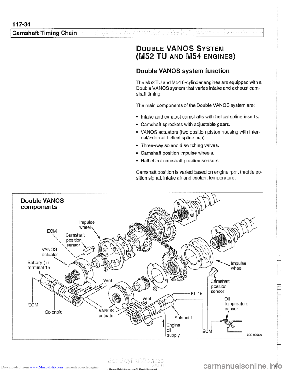
Double VANOS system function
The M52TU and M54 6-cylinder engines are equipped with a
Double VANOS system that varies intake and exhaust cam-
shaft timing.
The main components of the Double VANOS system are:
lntalte and exhaust camshafts with helical spline inserts.
Camshaft sprockets with adjustable gears.
VANOS actuators (two position piston housing with
inter-
nallexternal helical spline cup).
Three-way solenoid switching valves.
Camshaft position impulse wheels.
Hall effect camshaft position sensors.
Camshaft position
IS varied based on engine rpm, throttle po-
sition signal, intake air and coolant temperature.
Page 307 of 1002
Downloaded from www.Manualslib.com manuals search engine
Camshaft Timing chain1
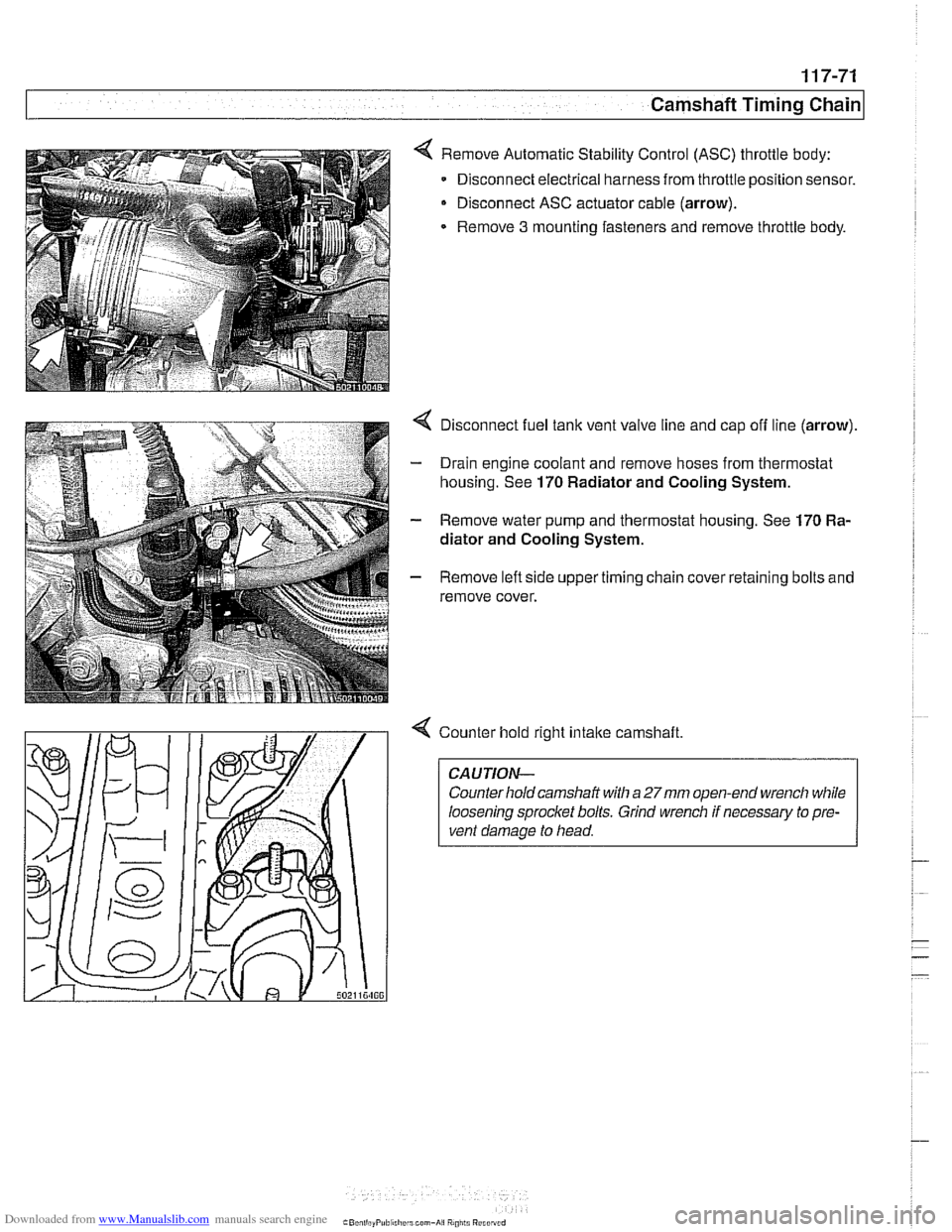
< Remove Automatic Stability Control (ASC) throttle body:
Disconnect electrical harness from throttle position sensor.
Disconnect ASC actuator cable (arrow).
Remove
3 mounting fasteners and remove throttle body.
4 Disconnect fuel tank vent valve line and cap off line (arrow).
- Drain engine coolant and remove hoses from thermostat
housing. See
170 Radiator and Cooling System.
- Remove water pump and thermostat housing. See 170 Ra-
diator and Cooling System.
- Remove left side upper timing chain cover retaining bolts and
remove cover.
4 Counter hold right intake camshaft
CAUTION-
Counter hold camshaft with a 27mm open-end wrench while
loosening sprocket bolts. Grind wrench if necessary to pre-
vent damage to head.
Page 335 of 1002
Downloaded from www.Manualslib.com manuals search engine
... . . Lubrication sy=
Upper oil pan, removing and installing (V-8)
The engine oil pan removal procedure requires that the en-
gine be supported from the top and the front suspension
sub-
frame be lowered.
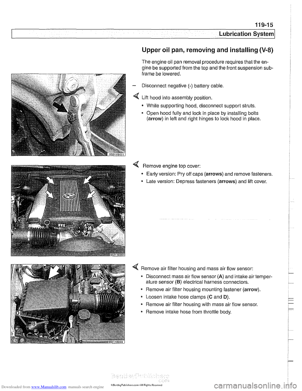
- Disconnect negative (-) battery cable
4 Lift hood into assembly position.
- While supporting hood, disconnect support struts.
Open hood
fully and lock in piace by installing bolts
(arrow) in left and right hinges to lock hood in place
4 Remove engine top cover:
- Early version: Pry off caps (arrows) and remove fasteners.
Late version: Depress fasteners (arrows) and lift cover.
4 Remove air filter housing and mass air flow sensor:
Disconnect mass air flow sensor
(A) and intake air temper-
ature sensor
(B) electrical harness connectors.
Remove air filter housing mounting fastener (arrow)
Loosen
intake hose clamps (C and D).
Remove air filter housing with mass air flow sensor.
Remove intake hose from throttle body.
Page 363 of 1002
Downloaded from www.Manualslib.com manuals search engine
120-15
Ignition system1
Exhaust camshaft position sensor, replacing
(M52 TU and M54 engines)
- Make sure ignition has been turned off.
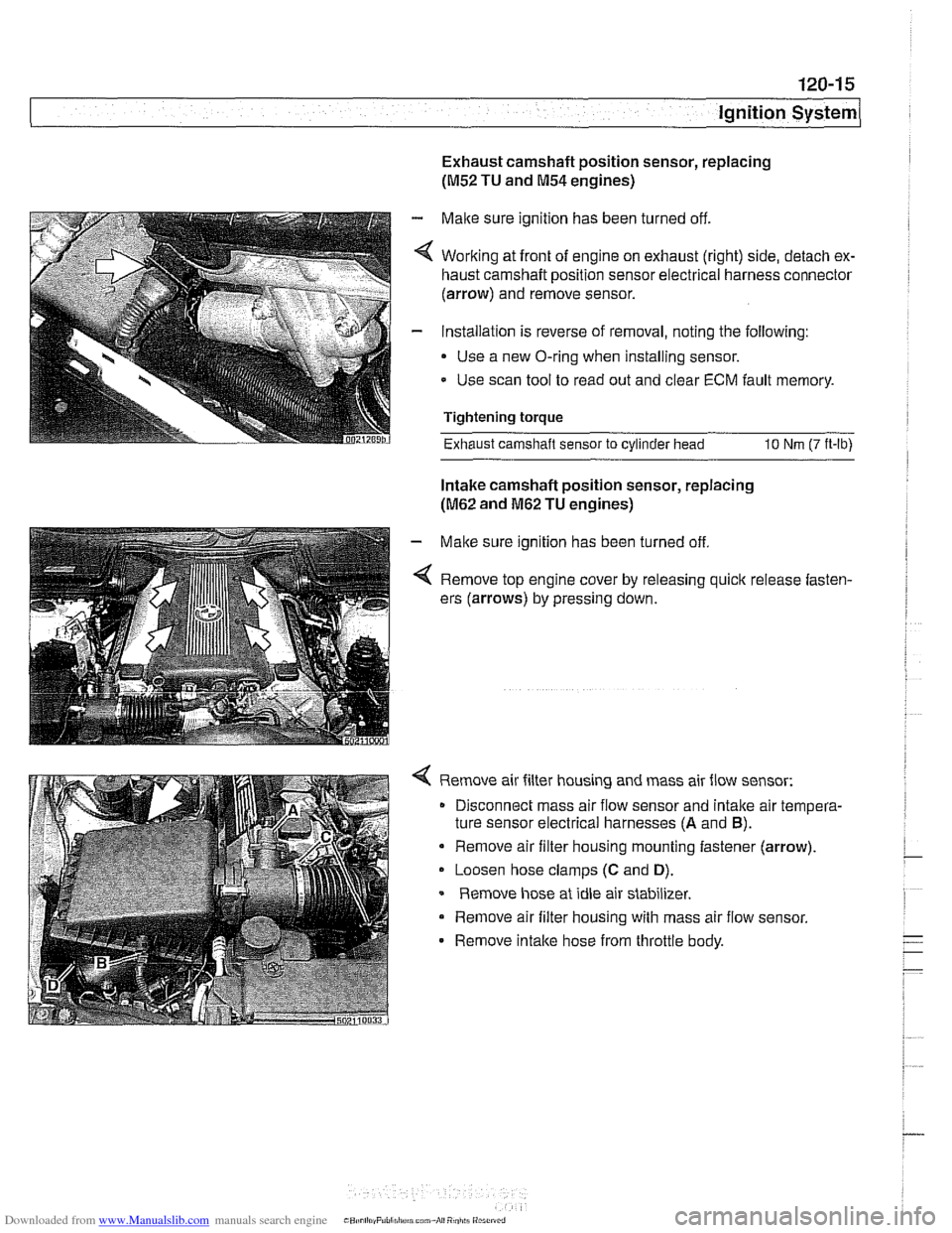
4 Working at front of engine on exhaust (right) side, detach ex-
haust camshaft position sensor electrical harness connector
(arrow) and remove sensor.
- Installation is reverse of removal, noting the following:
Use a new O-ring when installing sensor.
- Use scan tool to read out and clear ECM fault memory.
Tightening torque
Exhaust camshaft sensor
to cylinder head 10 Nm (7 ft-lb)
Intake camshaft position sensor, replacing
(M62 and M62 TU engines)
- Make sure ignition has been turned off
4 Remove top engine cover by releasing quick release fasten-
ers (arrows) by pressing down.
4 Remove air filter housing and mass air flow sensor:
Disconnect mass air flow sensor and
intalte air tempera-
ture sensor electrical harnesses
(A and B).
Remove air filter housing mounting fastener (arrow).
Loosen hose clamps
(C and D).
Remove hose at idle air stabilizer.
Remove air filter housing with mass air flow sensor.
- Remove intalte hose from throttle body.
Page 386 of 1002
Downloaded from www.Manualslib.com manuals search engine
I Battery, Starter, Alternator
- Check for battery voltage at terminal 50 of starter motor with
key in start position. If voltage is not present, check wiring be-
tween ignition switch and starter terminal. Check the EWS
system and other inputs that disrupt terminal
56 to the start-
er. See ELE Electrical
Wiring Diagrams. If voltage is
present and no other visible wiring faults can be found, prob-
lem is most likely in starter motor.
Starter, removing and installing
(6-cylinder engine)
The starter is removed from below. Access to starter bolts is
difficult. Be sure to have the proper tools on hand before pro-
ceeding.
NOTE-
Access to the starter wiring is very limited. Forbetteraccess,
it may be necessary to remove the intake manifold.
- Disconnect negative (-) battery cable.
CAUTIOI\C
Prior to disconnecting the battern read the baltery discon-
nection cautions
in OOlGeneral Cautions and Warnings.
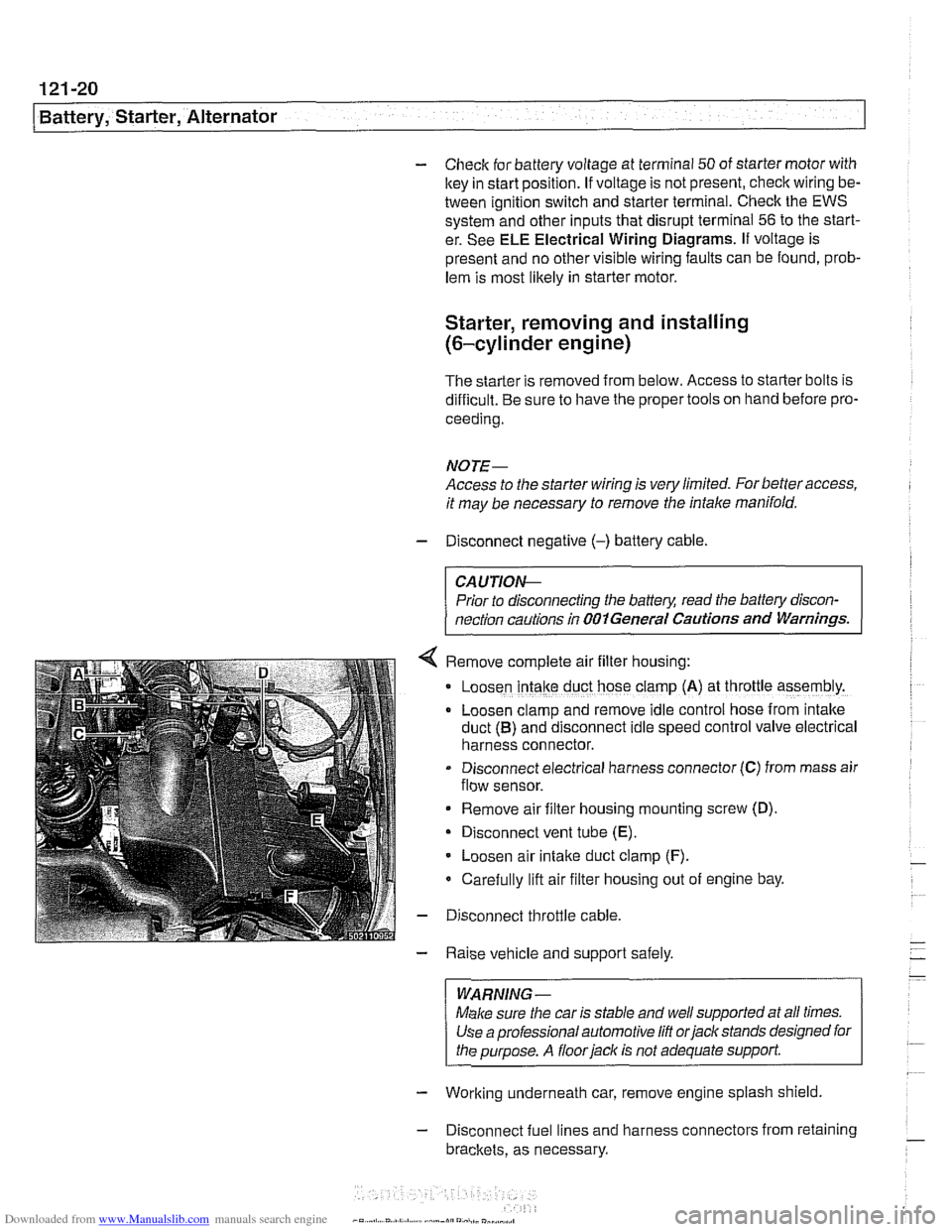
Remove complete air filter hous~ng:
Loosen intake duct hose clamp (A) at throttle assembly.
Loosen clamp and remove idle control hose from intake
duct
(B) and disconnect idle speed control valve electrical
harness connector.
Disconnect electrical harness connector
(C) from mass air
flow sensor.
Remove air filter housing mounting screw (D)
Disconnect vent tube
(E).
Loosen air intake duct clamp (F).
Carefully lift air filter housing out of engine bay.
Disconnect throttle cable.
Raise vehicle and support safely.
WARNING-
Make sure the car is stable and well supported at all times.
Use a professional automotive
lift orjack stands designed for
the purpose. A
floorjaclc is not adequate support
- Working underneath car, remove engine splash shield
- Disconnect fuel lines and harness connectors from retaining
brackets, as necessary.