BMW 528i 2001 E39 Workshop Manual
Manufacturer: BMW, Model Year: 2001, Model line: 528i, Model: BMW 528i 2001 E39Pages: 1002
Page 921 of 1002
Downloaded from www.Manualslib.com manuals search engine
........................ General ........................... .52 0.2 Rear Seats .52 0.7
SeatIMirrorlSteering Column Memory ..... .52 0.2 Rear seat cushion and backrest,
...... Seat memory position. setting ........... .52 0.2 removing and installing (sedan only) 520-7
......... Headrest. removing
and installing 520-8 Front Seats ........................ .52 0.4
Seat switch and memory module.
removing and installing
................ .52 0.3
Front seat. removing and installing
....... .52 0.5
Page 922 of 1002
Downloaded from www.Manualslib.com manuals search engine
l Seats
This repair group covers removal and installation of the front
and rear seat.
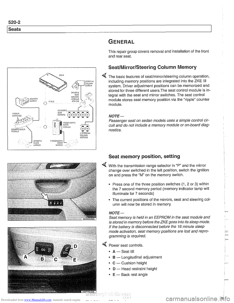
SeatIMirrorlSteering Column Memory
< The basic features of seaffmirrorlsteering column operation,
including memory positions are integrated into the
ZKE Ill
system. Driver adjustment positions can be memorized and
stored for three different
users.The seat control module is in-
tegral with the seat and mirror switches. The seat control
module stores seat memory position via the "ripple" counter
module.
NOTE-
Passenger seat on sedan models uses a simple control cir-
cuit and do not include a memory module or on-board diag-
nostics.
Seat memory position, setting
With the transmission range selector in "P and the mirror
change over switched in the left position, switch the ignition
on and press the
"M" on the memory switch.
Press one of the three position switches
(1, 2 or 3) within
the
7 second memory period (memory indicator lamp will
illuminate for
7 seconds)
- The current positions of the mirrors, seat and steering col-
umn will now be stored in memory.
NOTE- Seat memory is held in an
EEPROM in the seat module and
is stored in memory before the
ZKE goes into its sleep mode.
If the battery is disconnected before the 16 minute sleep
mode activation, seat memorypositions are lost and repro-
gramming is required.
< Power seat controls.
A -Seat tilt
B - Longitudinal adjustment
C - Cushion height
D - Head restraint height
E - Back rest angle
Page 923 of 1002
Downloaded from www.Manualslib.com manuals search engine
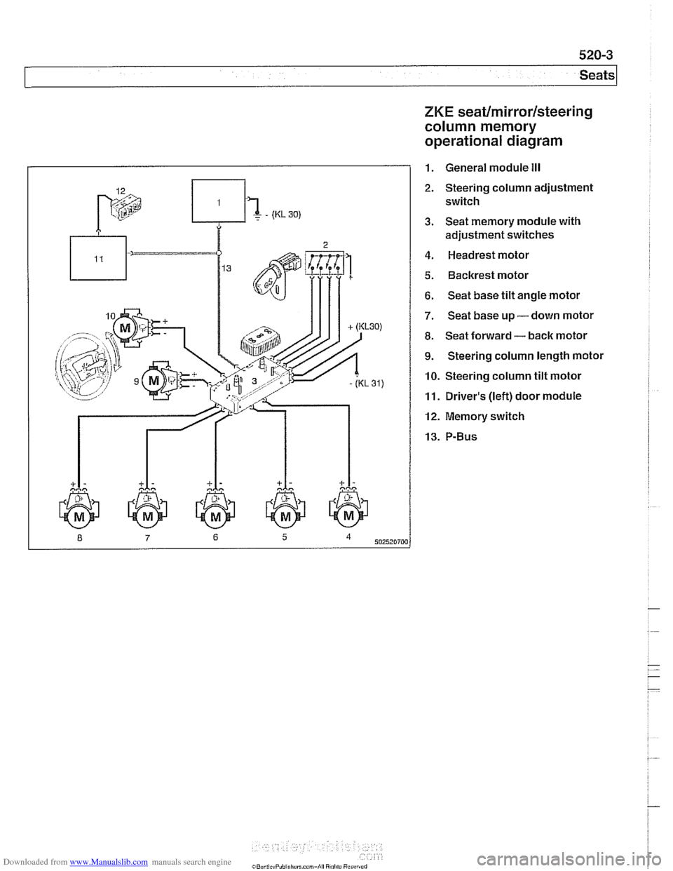
ZKE seat/mirror/steering
column memory
operational diagram
1. General module Ill
2. Steering column adjustment
switch
3. Seat memory module with
adjustment switches
4. Headrest motor
5. Backrest motor
6. Seat base tilt angle motor
7. Seat base up - down motor
8. Seat forward - back motor
9. Steering column length motor
10. Steering column tilt motor
11. Driver's (left) door module
12. Memory switch
Page 924 of 1002
Downloaded from www.Manualslib.com manuals search engine
l Seats
Seat repair and component replacement is possible once the
seat has been removed from the vehicle.
Before servicing front seats read safety regulations on han-
dling
airbag modules and pyrotechnic seatbelt tensioners.
See
720 Seat belts and 721 Airbag system (SRS).
WARNING-
. The front seats are equipped with pyrotechnic seat belt
tensioners. These tensioners are powerful devices and
should be handled with exfreme care. Incorrect handling
can trigger off the tensioner and cause injury.
BMW recommends that all repair or replacement
worlc
on pyrotechnic devices must be carried out by a quali-
fied
BMW technician.
Be sure to disconnect the battery and wait
5 seconds
before attempting to work on pyrotechnic devices.
During body straightening and welding with an electric
arc welder, always disconnect the battery and the con-
nection to the pyrotechnic gas generators.
Seat switch and memory module, removing
and installing
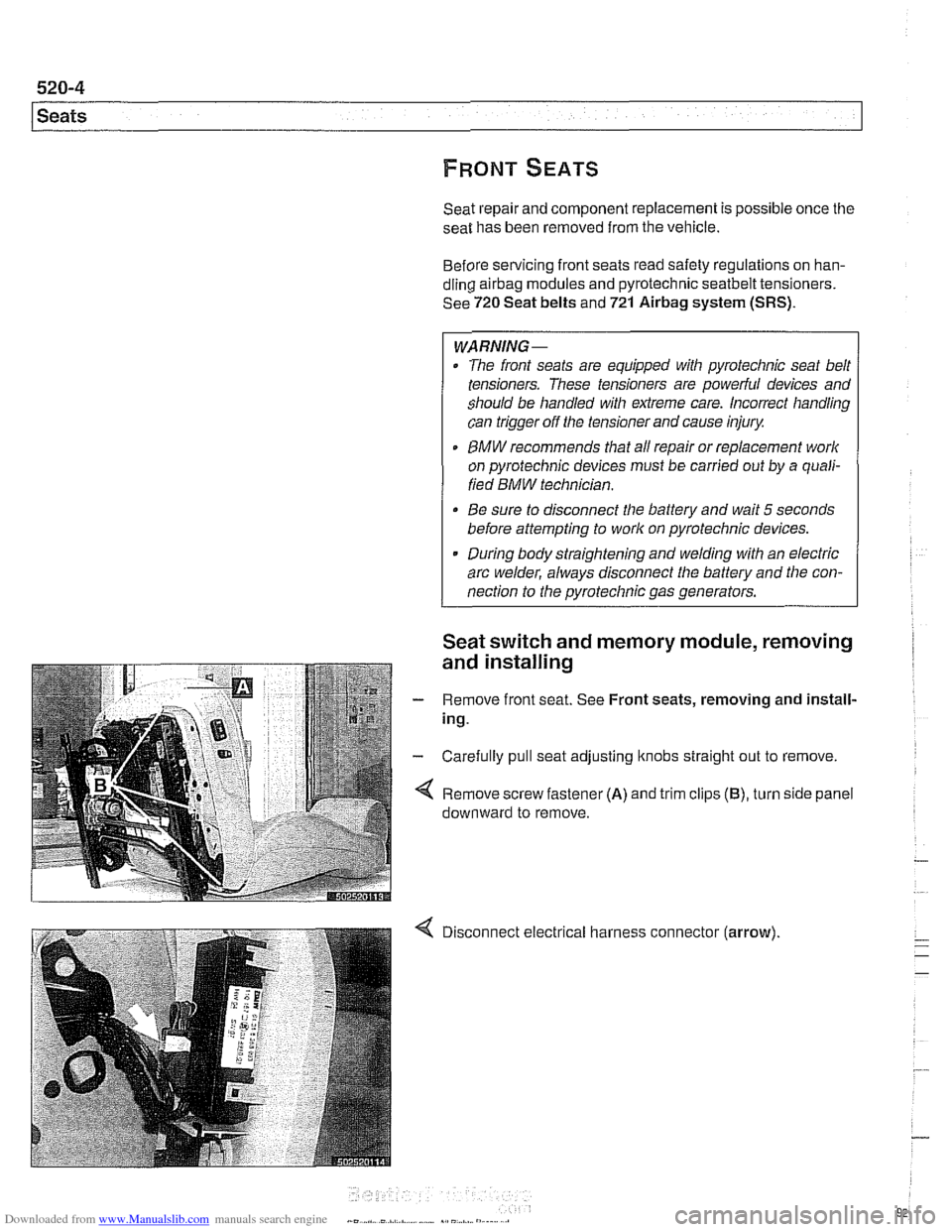
- Remove front seat. See Front seats, removing and install-
ing.
- Carefully pull seat adjusting ltnobs straight out to remove.
Remove screw fastener
(A) and trim clips (B), turn side panel
downward to remove.
Disconnect electrical harness connector
(arrow).
Page 925 of 1002
Downloaded from www.Manualslib.com manuals search engine
520-5
Seats
1
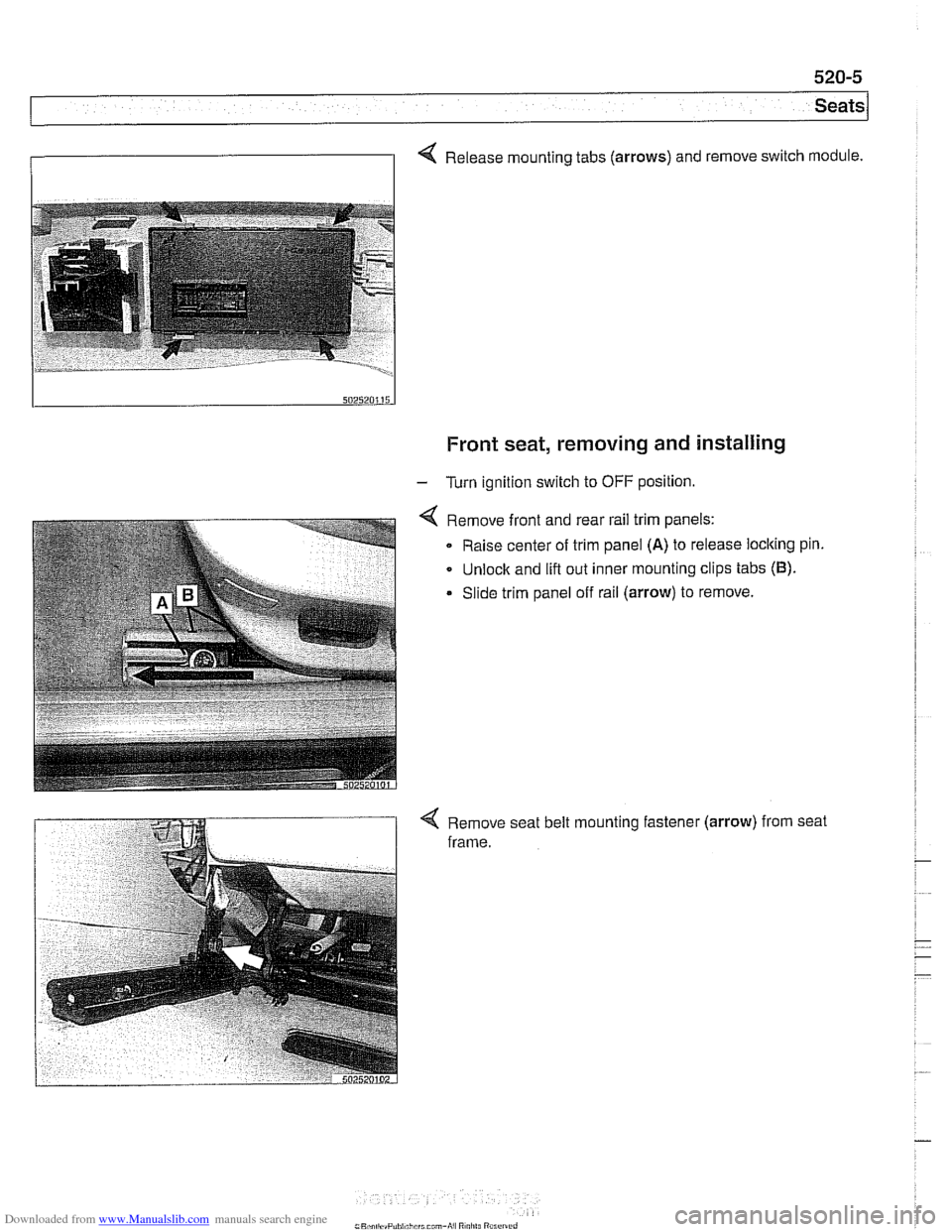
4 Release mounting tabs (arrows) and remove switch module.
Front seat, removing and installing
- Turn ignition switch to OFF position.
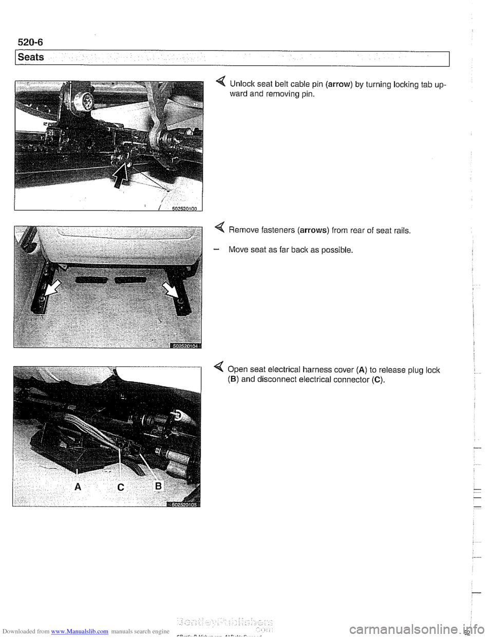
Remove front and rear rail trim panels:
Raise center of trim panel
(A) to release loclting pin.
Unlock and lift out inner mounting clips tabs
(6).
Slide trim panel off rail (arrow) to remove.
< Remove seat belt mounting fastener (arrow) from seat
frame.
Page 926 of 1002
Downloaded from www.Manualslib.com manuals search engine
--. .
1 Seats
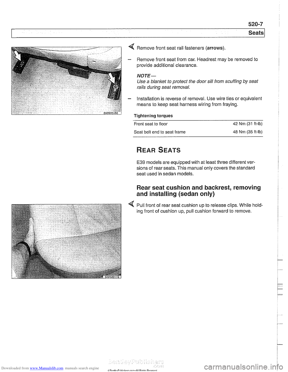
4 Remove fasteners (arrows) from rear
- Move seat as far back as possible. of
seat rails
4 Open seat electrical harness cover (A) to release plug loclc
(6) and disconnect electrical connector (C).
Page 927 of 1002
Downloaded from www.Manualslib.com manuals search engine
Seats
< Remove front seat rail fasteners (arrows)
- Remove front seat from car. Headrest may be removed to
provide additional clearance.
NOTE-
Use a blanket to protect the door sill from scuffing by seat
rails
during seat removal.
- Installation is reverse of removal. Use wire ties or equivalent
means to keep seat harness wiring from fraying.
Tightening torques
Front seat to floor
42 Nm (31 ft-lb)
Seat belt end to seat frame
48 Nm (35 ft-lb)
E39 models are equipped with at least three different ver-
sions of rear seats. This manual only covers the standard
seat used in sedan models.
Rear seat cushion and backrest, removing
and installing (sedan only)
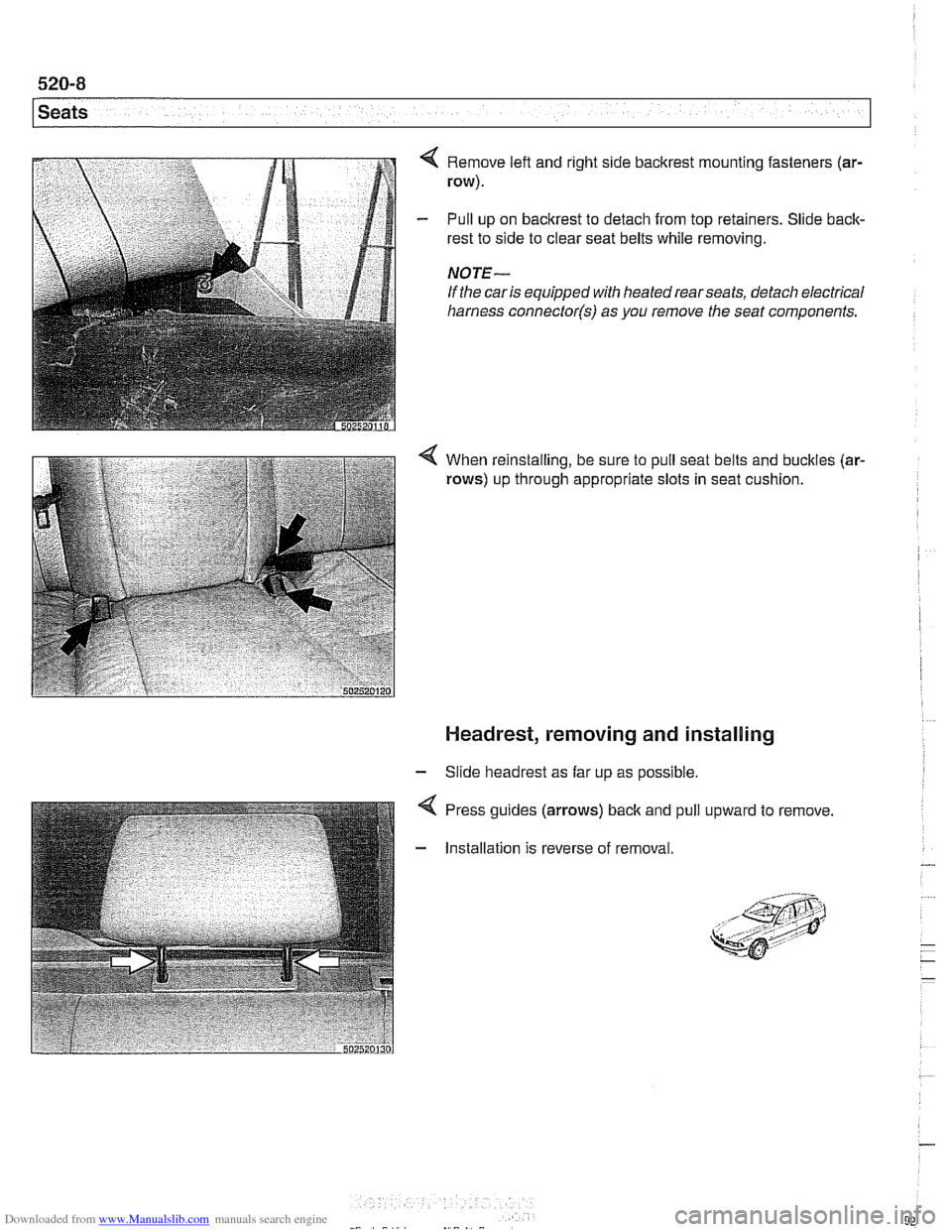
4 Pull front of rear seat cushion up to release clips. While hold-
ing front of cushion up, pull cushion forward to remove.
Page 928 of 1002
Downloaded from www.Manualslib.com manuals search engine
Seats
Remove left and right side bacltrest mounting fasteners (ar-
row).
Pull up on backrest to detach from top retainers. Slide back-
rest to side to clear seat belts while removing.
NOTE-
If the car is equipped with heatedrearseats, detach electrical
harness
connector(s) as you remove the seat components.
4 When reinstalling, be sure to pull seat belts and buckles (ar-
rows) up through appropriate slots in seat cushion.
Headrest, removing and installing
- Slide headrest as far up as possible.
Press guides (arrows)
back and
Installation is reverse of removal pull
upward to remove
Page 929 of 1002
Downloaded from www.Manualslib.com manuals search engine
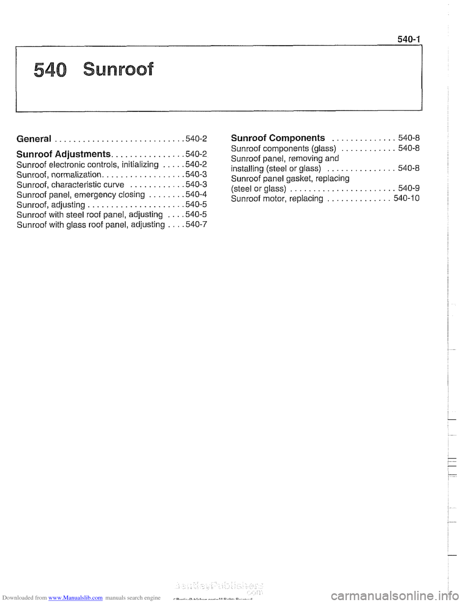
540 Sunroof
General . . . . . . . . . . . . . . . . . . . . . . . . . . . ,540-2
Sunroof Adjustments. . . . . . . . . . . . . . . .540-2
Sunroof electronic controls, initializing . . . . ,540-2
Sunroof, normalization. . . . . . . . . . . . . . . . . ,540-3
Sunroof, characteristic curve . . . . . . . . . . . .540-3
Sunroof panel, emergency closing . . . . . . . ,540-4
Sunroof, adiustino . . . . . . . . . . . . . . . . . . . . ,540-5
~unroofwitil steel roof panel, adjusting . . . ,540-5
Sunroof with glass roof panel, adjusting . . . ,540-7
Sunroof Components . . . . . . . . . . . . . . 540-8
Sunroof components (glass)
. . . . . . . . . . . . 540-8
Sunroof panel, removing and
installing (steel or glass)
. . . . . . . . . . . . . . . 540-8
Sunroof panel gasket, replacing
(steel or glass)
. . . . . . . . . . . . . . . . . . . . . . . 540-9
Sunroof motor, replacing
. . . . . . . . . . . . . . 540-10
Page 930 of 1002
Downloaded from www.Manualslib.com manuals search engine
540-2
Sunroof
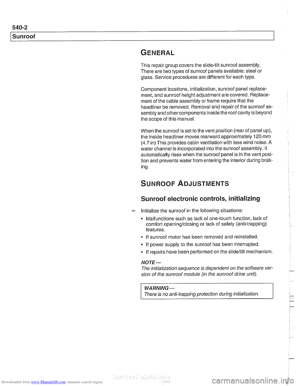
This repair group covers the slide-tilt sunroof assembly.
There are two types of sunroof panels available: steel
01
glass. Service procedures are different for each type.
Component locations, initialization, sunroof panel replace-
ment, and sunroof height adjustment are covered. Replace-
ment of the cable assembly or frame require that the
headliner be removed. Removal and repair of the sunroof as-
sembly and othercomponents inside the roof cavity is beyond
the scope of this manual.
When the sunroof is set to the vent position (rear of panel up),
the inside headliner moves rearward approximately
120 mm
(4.7 in) This provides cabin ventilation with less wind noise. A
water channel is incorporated into the sunroof assembly. It
automatically rises when the sunroof panel is in the vent posi-
tion and prevents water from entering the interior during brak-
ing.
Sunroof electronic controls, initializing
- Initialize the sunroof in the following situations:
Malfunctions
such as lack of one-touch function, lack of
comfort openinglclosing or lack of safety (anti-trapping)
features.
If sunroof motor has been removed and reinstalled.
If power supply to the sunroof has been interrupted.
If repairs have been performed on the slideltilt mechanism.
NOTE -
The initialization sequence is dependent on the software ver-
sion of
tlie sunroof module (in the sunroof drive unit).
I WARNING -
I There is no anti-trapping protection during initialization. I