low BMW 528I XDRIVE SEDAN 2014 Owner's Manual
[x] Cancel search | Manufacturer: BMW, Model Year: 2014, Model line: 528I XDRIVE SEDAN, Model: BMW 528I XDRIVE SEDAN 2014Pages: 273
Page 53 of 273
▷ Pull the reel to the resistance point.
The window closes while the reel is held.▷ Pull the reel beyond the resistance
point.
The window closes automatically. Pulling
again stops the motion.
See also: closing by means of Comfort Access,
refer to page 42.
Pinch protection system Danger of jamming even with pinch pro‐
tection
Even with the pinch protection system, check
that the window's closing path is clear; other‐
wise, the closing action may not stop in certain
situations, e.g., if thin objects are present.◀
No window accessories
Do not install any accessories in the win‐
dow's range of movement; otherwise, the
pinch protection system will be impaired.◀
If closing force exceeds a specific margin as a
window closes, closing is interrupted.
The window reopens slightly.
Closing without the pinch protection
system
Keep the closing path clear
Monitor closing and make sure that the
closing path of the window is clear; otherwise,
injuries may result.◀
E.g. danger from the outside or ice might pre‐
vent window from closing properly - proceed
as follows:
1.Pull the reel past the resistance point and
hold it there.
The pinch protection is limited and the
window reopens slightly if the closing force
exceeds a certain margin.2.Pull the reel past the resistance point again
within approx. 4 seconds and hold it there.
The window closes without jam protection.
Safety reel
General information
The safety reel in the driver's door can be used
to prevent children, e.g., from opening and
closing the rear windows using the switches in
the rear.
Switching on and off Press button.
The LED lights up if the safety func‐
tion is switched on.
Safety reel for rear operation
Press the safety reel when transporting
children in the rear; otherwise, injury may re‐
sult if the windows are closed without supervi‐
sion.◀
Roller sunblinds
General information
If you are no longer able to move the roller sun‐
blind for the rear window after having activated
it a number of times in a row, the system is
blocked for a limited time to prevent overheat‐
ing. Let the system cool.
The roller sunblind for the rear window cannot
be moved at low interior temperatures.
Seite 49Opening and closingControls49
Online Edition for Part no. 0140 2 956 218 - X/14
Page 55 of 273
The sliding visor opens automatically. If the
sliding visor is already fully open, the glass
sunroof opens automatically.
The glass sunroof closes automatically. If
the glass sunroof is already closed or in the
tilted position, the sliding visor closes au‐
tomatically.
Pressing the reel upward stops the motion.
Opening/closing the glass sunroof and
sliding visor together
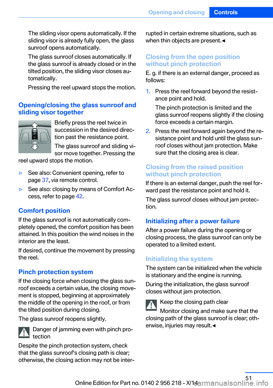
Briefly press the reel twice in
succession in the desired direc‐
tion past the resistance point.
The glass sunroof and sliding vi‐
sor move together. Pressing the
reel upward stops the motion.
▷See also: Convenient opening, refer to
page 37, via remote control.▷See also: closing by means of Comfort Ac‐
cess, refer to page 42.
Comfort position
If the glass sunroof is not automatically com‐
pletely opened, the comfort position has been
attained. In this position the wind noises in the
interior are the least.
If desired, continue the movement by pressing
the reel.
Pinch protection system
If the closing force when closing the glass sun‐
roof exceeds a certain value, the closing move‐
ment is stopped, beginning at approximately
the middle of the opening in the roof, or from
the tilted position during closing.
The glass sunroof reopens slightly.
Danger of jamming even with pinch pro‐
tection
Despite the pinch protection system, check
that the glass sunroof's closing path is clear;
otherwise, the closing action may not be inter‐
rupted in certain extreme situations, such as
when thin objects are present.◀
Closing from the open position
without pinch protection
E. g. if there is an external danger, proceed as
follows:1.Press the reel forward beyond the resist‐
ance point and hold.
The pinch protection is limited and the
glass sunroof reopens slightly if the closing
force exceeds a certain margin.2.Press the reel forward again beyond the re‐
sistance point and hold until the glass sun‐
roof closes without jam protection. Make
sure that the closing area is clear.
Closing from the raised position
without pinch protection
If there is an external danger, push the reel for‐
ward past the resistance point and hold it.
The glass sunroof closes without jam protec‐
tion.
Initializing after a power failure After a power failure during the opening or
closing process, the glass sunroof can only be
operated to a limited extent.
Initializing the system
The system can be initialized when the vehicle
is stationary and the engine is running.
During the initialization, the glass sunroof
closes without jam protection.
Keep the closing path clear
Monitor closing and make sure that the
closing path of the glass sunroof is clear; oth‐
erwise, injuries may result.◀
Seite 51Opening and closingControls51
Online Edition for Part no. 0140 2 956 218 - X/14
Page 59 of 273
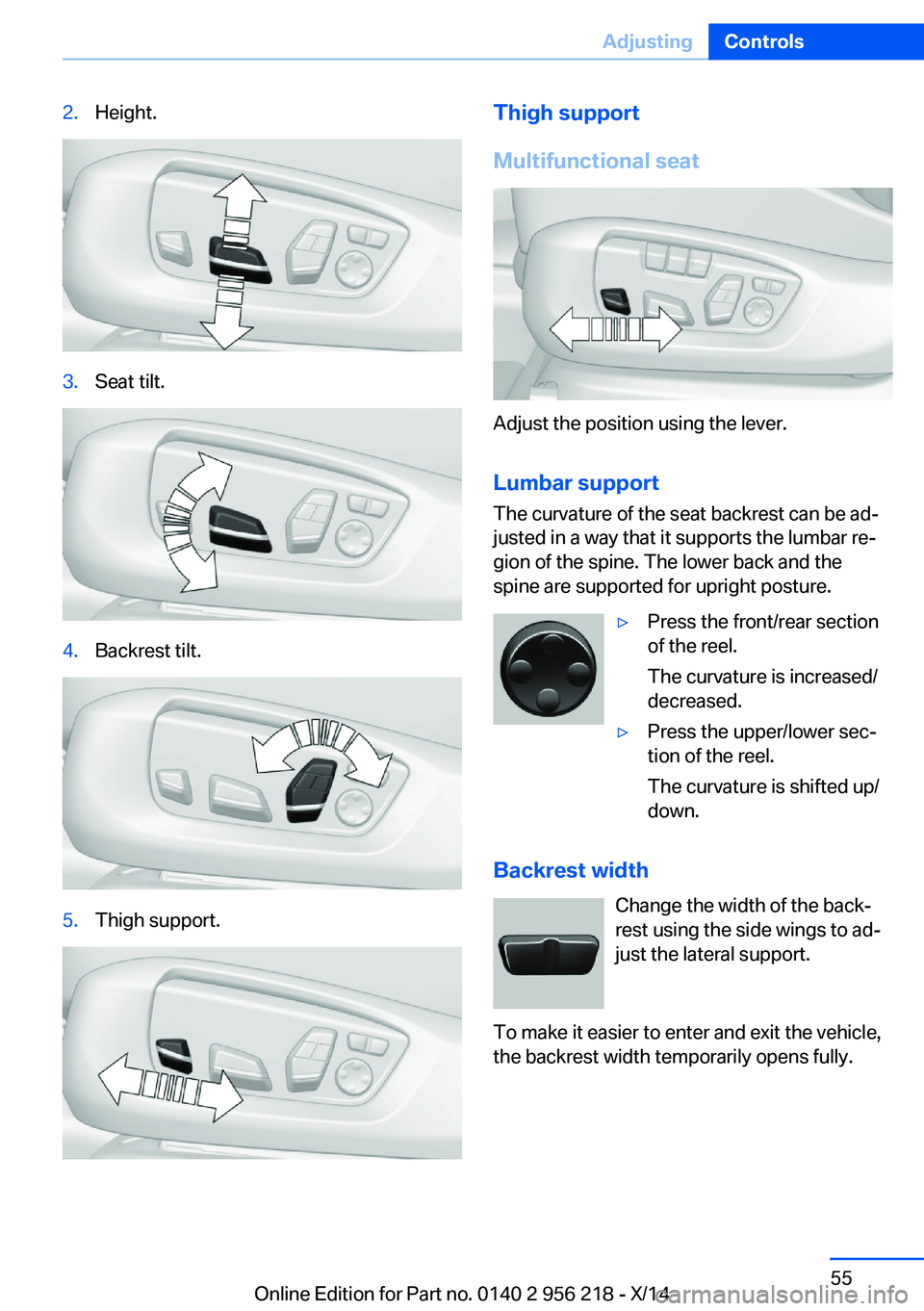
2.Height.3.Seat tilt.4.Backrest tilt.5.Thigh support.Thigh support
Multifunctional seat
Adjust the position using the lever.
Lumbar support
The curvature of the seat backrest can be ad‐
justed in a way that it supports the lumbar re‐
gion of the spine. The lower back and the
spine are supported for upright posture.
▷Press the front/rear section
of the reel.
The curvature is increased/
decreased.▷Press the upper/lower sec‐
tion of the reel.
The curvature is shifted up/
down.
Backrest width
Change the width of the back‐
rest using the side wings to ad‐
just the lateral support.
To make it easier to enter and exit the vehicle,
the backrest width temporarily opens fully.
Seite 55AdjustingControls55
Online Edition for Part no. 0140 2 956 218 - X/14
Page 60 of 273
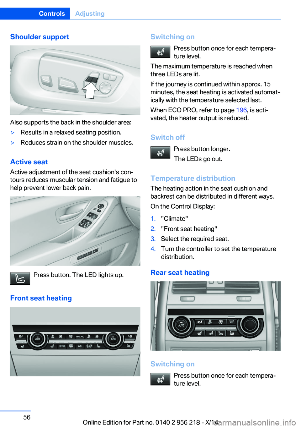
Shoulder support
Also supports the back in the shoulder area:
▷Results in a relaxed seating position.▷Reduces strain on the shoulder muscles.
Active seatActive adjustment of the seat cushion's con‐
tours reduces muscular tension and fatigue to
help prevent lower back pain.
Press button. The LED lights up.
Front seat heating
Switching on Press button once for each tempera‐
ture level.
The maximum temperature is reached when
three LEDs are lit.
If the journey is continued within approx. 15
minutes, the seat heating is activated automat‐
ically with the temperature selected last.
When ECO PRO, refer to page 196, is acti‐
vated, the heater output is reduced.
Switch off Press button longer.
The LEDs go out.
Temperature distribution
The heating action in the seat cushion and
backrest can be distributed in different ways.
On the Control Display:1."Climate"2."Front seat heating"3.Select the required seat.4.Turn the controller to set the temperature
distribution.
Rear seat heating
Switching on
Press button once for each tempera‐
ture level.
Seite 56ControlsAdjusting56
Online Edition for Part no. 0140 2 956 218 - X/14
Page 61 of 273
The maximum temperature is reached when
three LEDs are lit.
If the journey is continued within approx. 15
minutes, the seat heating is activated automat‐
ically with the temperature selected last.
When ECO PRO, refer to page 196, is acti‐
vated, the heater output is reduced.
Switch off Press button longer.
The LEDs go out.
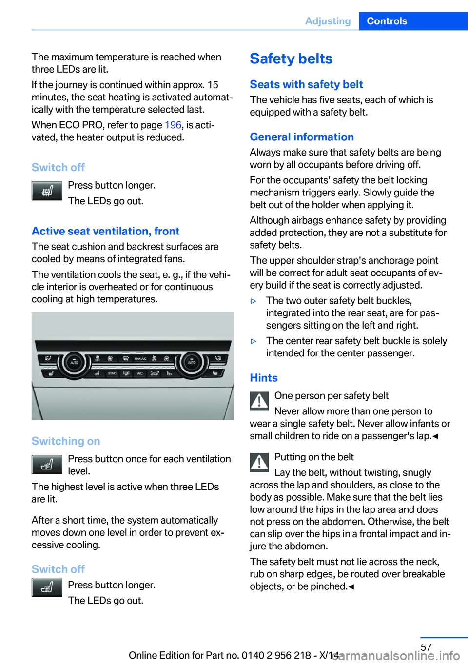
Active seat ventilation, front The seat cushion and backrest surfaces are
cooled by means of integrated fans.
The ventilation cools the seat, e. g., if the vehi‐
cle interior is overheated or for continuous
cooling at high temperatures.
Switching on
Press button once for each ventilation
level.
The highest level is active when three LEDs
are lit.
After a short time, the system automatically
moves down one level in order to prevent ex‐
cessive cooling.
Switch off Press button longer.
The LEDs go out.
Safety belts
Seats with safety belt
The vehicle has five seats, each of which is
equipped with a safety belt.
General information
Always make sure that safety belts are being
worn by all occupants before driving off.
For the occupants' safety the belt locking
mechanism triggers early. Slowly guide the
belt out of the holder when applying it.
Although airbags enhance safety by providing
added protection, they are not a substitute for
safety belts.
The upper shoulder strap's anchorage point
will be correct for adult seat occupants of ev‐
ery build if the seat is correctly adjusted.▷The two outer safety belt buckles,
integrated into the rear seat, are for pas‐
sengers sitting on the left and right.▷The center rear safety belt buckle is solely
intended for the center passenger.
Hints
One person per safety belt
Never allow more than one person to
wear a single safety belt. Never allow infants or
small children to ride on a passenger's lap.◀
Putting on the belt
Lay the belt, without twisting, snugly
across the lap and shoulders, as close to the
body as possible. Make sure that the belt lies
low around the hips in the lap area and does
not press on the abdomen. Otherwise, the belt
can slip over the hips in a frontal impact and in‐
jure the abdomen.
The safety belt must not lie across the neck,
rub on sharp edges, be routed over breakable
objects, or be pinched.◀
Seite 57AdjustingControls57
Online Edition for Part no. 0140 2 956 218 - X/14
Page 63 of 273
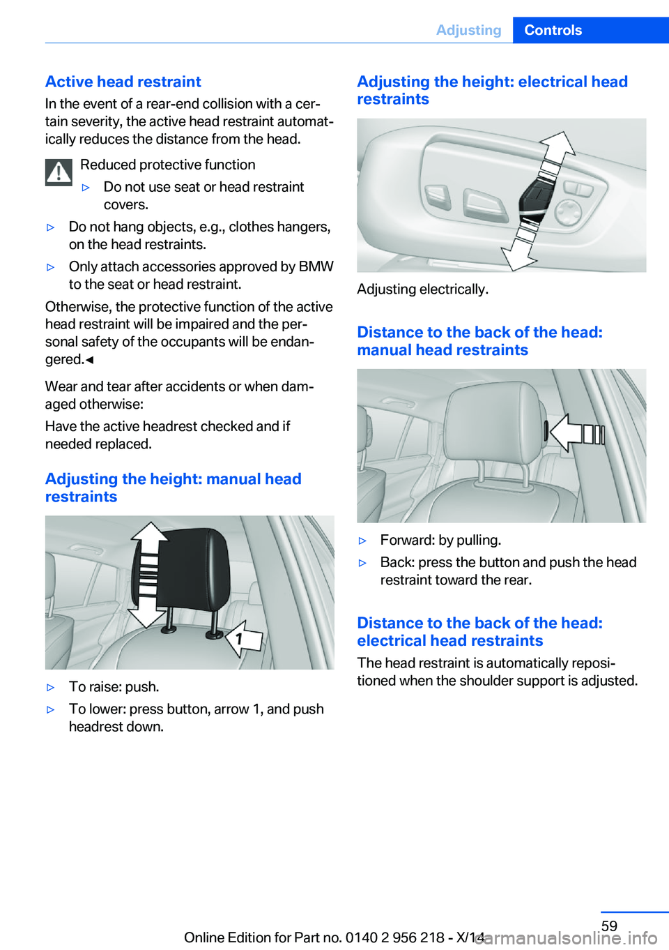
Active head restraintIn the event of a rear-end collision with a cer‐
tain severity, the active head restraint automat‐
ically reduces the distance from the head.
Reduced protective function▷Do not use seat or head restraint
covers.▷Do not hang objects, e.g., clothes hangers,
on the head restraints.▷Only attach accessories approved by BMW
to the seat or head restraint.
Otherwise, the protective function of the active
head restraint will be impaired and the per‐
sonal safety of the occupants will be endan‐
gered.◀
Wear and tear after accidents or when dam‐
aged otherwise:
Have the active headrest checked and if
needed replaced.
Adjusting the height: manual head
restraints
▷To raise: push.▷To lower: press button, arrow 1, and push
headrest down.Adjusting the height: electrical head
restraints
Adjusting electrically.
Distance to the back of the head:
manual head restraints
▷Forward: by pulling.▷Back: press the button and push the head
restraint toward the rear.
Distance to the back of the head:
electrical head restraints
The head restraint is automatically reposi‐
tioned when the shoulder support is adjusted.
Seite 59AdjustingControls59
Online Edition for Part no. 0140 2 956 218 - X/14
Page 64 of 273
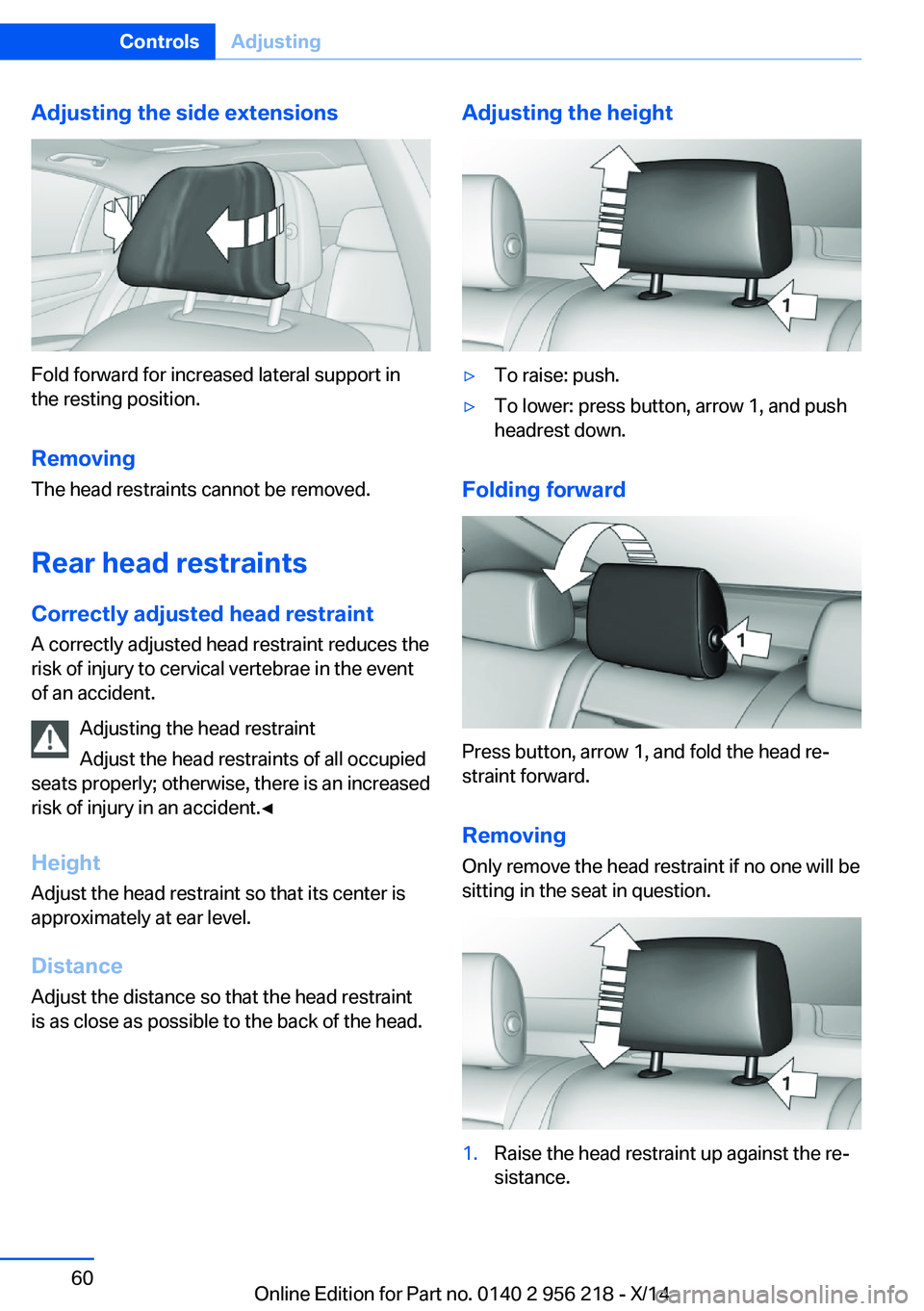
Adjusting the side extensions
Fold forward for increased lateral support in
the resting position.
Removing The head restraints cannot be removed.
Rear head restraints
Correctly adjusted head restraint A correctly adjusted head restraint reduces the
risk of injury to cervical vertebrae in the event
of an accident.
Adjusting the head restraint
Adjust the head restraints of all occupied
seats properly; otherwise, there is an increased
risk of injury in an accident.◀
Height
Adjust the head restraint so that its center is
approximately at ear level.
Distance
Adjust the distance so that the head restraint
is as close as possible to the back of the head.
Adjusting the height▷To raise: push.▷To lower: press button, arrow 1, and push
headrest down.
Folding forward
Press button, arrow 1, and fold the head re‐
straint forward.
Removing Only remove the head restraint if no one will be
sitting in the seat in question.
1.Raise the head restraint up against the re‐
sistance.Seite 60ControlsAdjusting60
Online Edition for Part no. 0140 2 956 218 - X/14
Page 66 of 273
Mirrors
Exterior mirrors
General information The mirror on the passenger side is more
curved than the driver's side mirror.
Depending on the vehicle equipment, the mir‐
ror setting is stored for the profile currently in
use. When the vehicle is unlocked via the re‐
mote control, the position is automatically re‐
trieved if this function is active.
Note Estimating distances correctly
Objects reflected in the mirror are closer
than they appear. Do not estimate the distance
to the traffic behind you based on what you
see in the mirror, as this will increase your risk
of an accident.◀
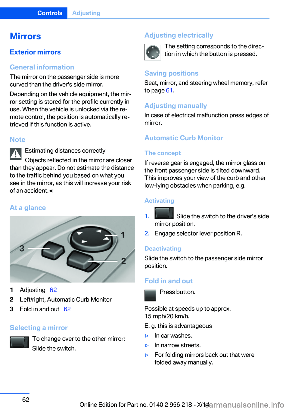
At a glance1Adjusting 622Left/right, Automatic Curb Monitor3Fold in and out 62
Selecting a mirror
To change over to the other mirror:
Slide the switch.
Adjusting electrically
The setting corresponds to the direc‐
tion in which the button is pressed.
Saving positions
Seat, mirror, and steering wheel memory, refer
to page 61.
Adjusting manually In case of electrical malfunction press edges of
mirror.
Automatic Curb Monitor
The concept
If reverse gear is engaged, the mirror glass on
the front passenger side is tilted downward.
This improves your view of the curb and other
low-lying obstacles when parking, e.g.
Activating1. Slide the switch to the driver's side
mirror position.2.Engage selector lever position R.
Deactivating
Slide the switch to the passenger side mirror
position.
Fold in and out Press button.
Possible at speeds up to approx.
15 mph/20 km/h.
E. g. this is advantageous
▷In car washes.▷In narrow streets.▷For folding mirrors back out that were
folded away manually.Seite 62ControlsAdjusting62
Online Edition for Part no. 0140 2 956 218 - X/14
Page 70 of 273

of unexpected movement of the rear seat
backrest.◀
On the front passenger seat
Deactivating airbags Deactivating the front-seat passenger
airbags
If a child restraint system is used in the front
passenger seat, deactivate the front-seat pas‐
senger airbags; otherwise, there is an in‐
creased risk of injury to the child when the air‐
bags are activated, even with a child restraint
system.◀
After installing a child restraint system in the
front passenger seat, make sure that the front,
knee and side airbags on the front passenger
side are deactivated.
Deactivate the front-seat passenger airbags
automatically, refer to page 110.
Seat position and height
Before installing a child restraint system, move
the front passenger seat as far back as possi‐
ble and bring it up to medium height to obtain
the best possible position for the belt and to
offer optimal protection in the event of an acci‐
dent.
If the upper anchorage of the safety belt is lo‐
cated in front of the belt guide of the child seat,
move the passenger seat carefully forward un‐
til the best possible belt guide position is
reached.Child seat security
The rear safety belts and the front passenger
safety belt can be permanently locked to fas‐
ten child restraint systems.
Locking the safety belt
1.Pull out the strap completely.2.Secure the child restraint system with the
belt.3.Allow the strap to be pulled in and pull it
tight against the child restraint system.
The safety belt is locked.
Unlocking the safety belt
1.Unbuckle the belt buckle.2.Remove the child restraint system.3.Allow the strap to be pulled in completely.
LATCH child restraint
system
LATCH: Lower Anchors and Tether for Chil‐
dren.
Note Follow manufacturer's information for
LATCH child restraint systems
To mount and use the LATCH child restraint
systems, observe the operating and safety in‐
formation from the system manufacturer; oth‐
erwise, the level of protection may be re‐
duced.◀
Seite 66ControlsTransporting children safely66
Online Edition for Part no. 0140 2 956 218 - X/14
Page 71 of 273
Mounts for the lower LATCH anchorsThe lower anchors may be used to attach the
CRS to the vehicle seat up to a combined child
and CRS weight of 65 lb/30 kg when the child
is restrained by the internal harnesses.
Properly engage the lower LATCH an‐
chors
Make sure that the lower LATCH anchors have
properly engaged and that the child restraint
system is resting snugly against the backrest;
otherwise, the degree of protection may be re‐
duced.◀
Before mounting the LATCH child restraint
system, pull the belt away from the child re‐
straint system.
The corresponding symbol shows the
mounts for the lower LATCH anchors.
Without a through-loading system:
Position
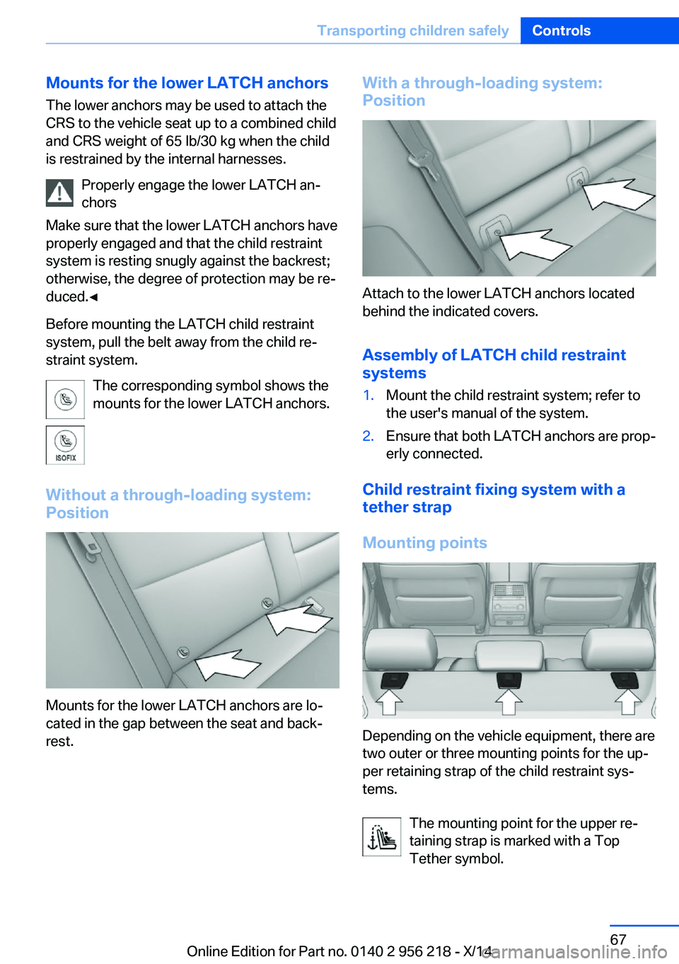
Mounts for the lower LATCH anchors are lo‐
cated in the gap between the seat and back‐
rest.
With a through-loading system:
Position
Attach to the lower LATCH anchors located
behind the indicated covers.
Assembly of LATCH child restraint
systems
1.Mount the child restraint system; refer to
the user's manual of the system.2.Ensure that both LATCH anchors are prop‐
erly connected.
Child restraint fixing system with a
tether strap
Mounting points
Depending on the vehicle equipment, there are
two outer or three mounting points for the up‐
per retaining strap of the child restraint sys‐
tems.
The mounting point for the upper re‐
taining strap is marked with a Top
Tether symbol.
Seite 67Transporting children safelyControls67
Online Edition for Part no. 0140 2 956 218 - X/14