Abs wiring BMW 530i 1997 E39 Workshop Manual
[x] Cancel search | Manufacturer: BMW, Model Year: 1997, Model line: 530i, Model: BMW 530i 1997 E39Pages: 1002
Page 89 of 1002
Downloaded from www.Manualslib.com manuals search engine
- .. -.
-. Engine Removal and in=/
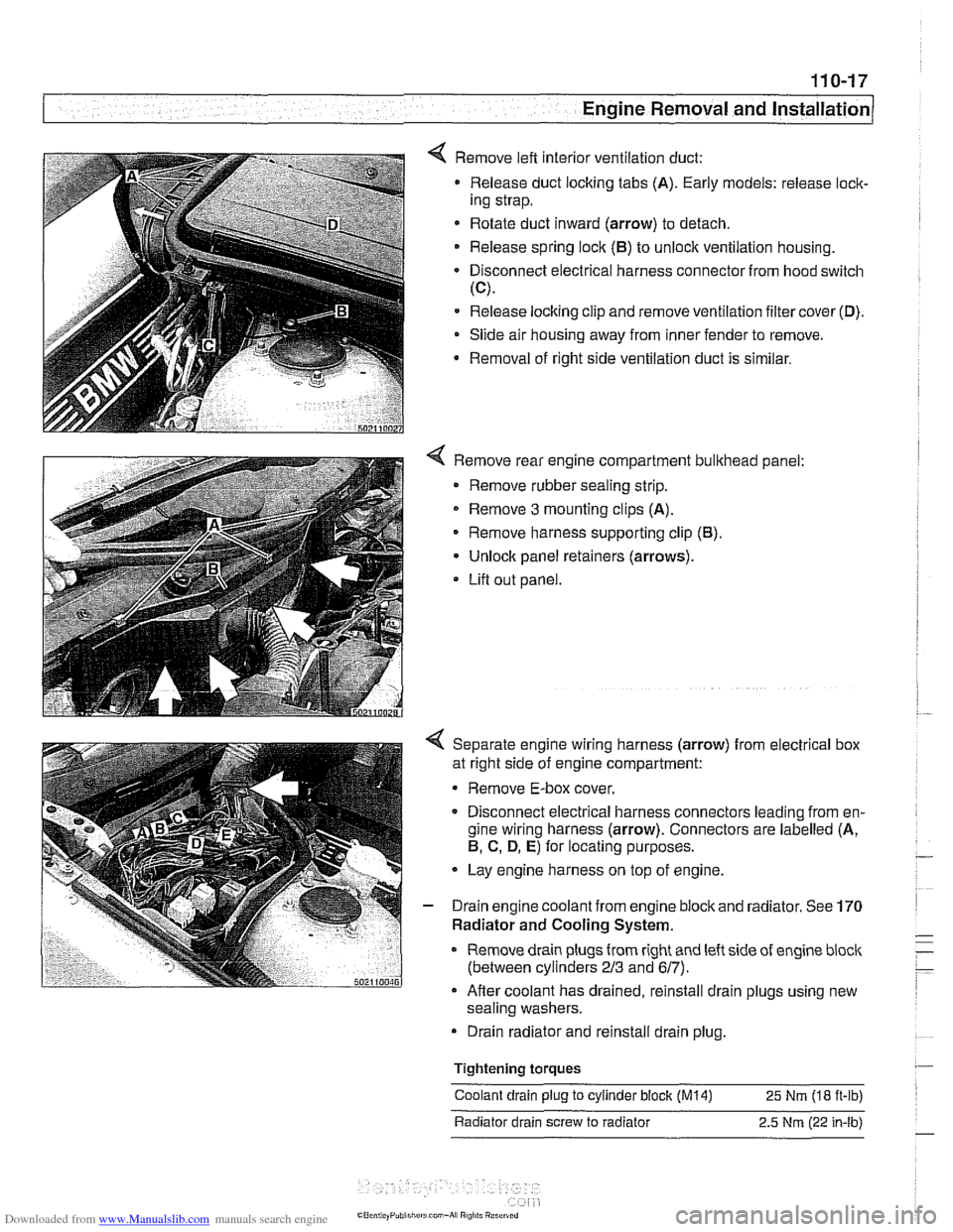
4 Remove left interior ventilation duct:
Release duct locking tabs (A). Early models: release
loclc
ing strap.
* Rotate duct inward (arrow) to detach.
Release spring
loclc (El) to unlock ventilation housing.
Disconnect electrical harness connector from hood switch
(C).
Release locking clip and remove ventilation filter cover (D).
Slide air housing away from inner fender to remove.
Removal
of right side ventilation duct is similar.
4 Remove rear engine compartment bulkhead panel:
Remove rubber sealing strip.
* Remove 3 mounting clips (A).
Remove harness supporting clip
(El).
Unlock panel retainers (arrows).
Lifl out panel.
< Separate engine wiring harness (arrow) from electrical box
at right side of engine compartment:
Remove E-box cover.
Disconnect electrical harness connectors leading from en-
gine wiring harness (arrow). Connectors are labelled (A,
El, C. D, E) for locating purposes.
Lay engine harness on top of engine.
- Drain engine coolant from engine block and radiator. See 170
Radiator and Cooling System.
Remove drain plugs from right and left side of engine
bloclc
(between cylinders 213 and 617).
Afler coolant has drained, reinstall drain plugs using new
sealing washers.
Drain radiator and reinstall drain plug.
Tightening
torques
Coolant drain plug to cylinder block (M14) 25 Nm (18 ft-ib)
Radiator drain screw to radiator 2.5
Nm (22 in-lb)
Page 119 of 1002
Downloaded from www.Manualslib.com manuals search engine
11 3-25
Cylinder Head Removal and Installation
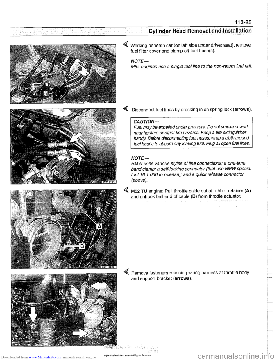
4 Working beneath car (on left side under driver seat), remove
fuel filter cover and clamp
off fuel hose(s).
NOTE-
M54 engines use a single fuel line to the non-return fuel rail.
Disconnect fuel lines by pressing in on spring lock (arrows).
CAUTION--
Fuel may be expelled underpressure. Do not smoke or worlc
near heaters or other fire hazards. Keep a fire extinguisher
handy Before disconnecting fuel hoses, wrap a cloth around
fuel hoses to absorb any leaking fuel. Plug all open fuel lines.
NOJE-
BMW uses various styles of line connections; a one-time
band clamp; a
self-locl(ing connector (that use BMWspecial
tool 16 1 050 to release); and a quick release connector
(above).
4 M52 TU engine: Pull throttle cable out of rubber retainer (A)
and unhook ball end of cable (6) from throttle actuator.
4 Remove fasteners retaining wiring harness at throttle body
and support bracket (arrows).
Page 719 of 1002
Downloaded from www.Manualslib.com manuals search engine
330-23
Rear Suspension
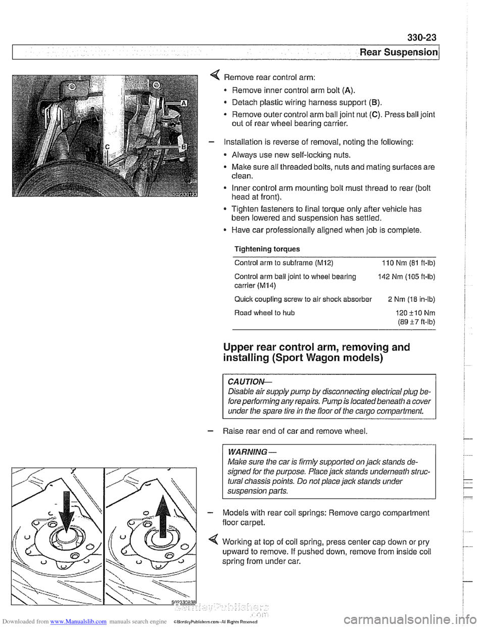
Remove rear control arm:
Remove inner control arm bolt
(A).
Detach plastic wiring harness support (B).
* Remove outer control arm ball joint nut (C). Press ball joint
out of rear wheel bearing carrier.
Installation is reverse of removal, noting the following:
Always use new self-locking nuts.
Malte sure all threaded bolts, nuts and mating surfaces are
clean.
Inner control arm mounting bolt must thread to rear (bolt
head at front).
Tighten fasteners to final torque only afler vehicle has
been lowered and suspension has settled.
Have car professionally aligned when job is complete.
Tightening
torques
Control arm to subframe (M12) 110 Nm (81 ft-ib)
Control arm
ball joint to wheel bearing 142 Nm (105 ft-lb)
carrier
(M14)
Quick coupling screw to air shock absorber
2 Nm (18 in-lb)
Road wheel
to hub 120-flONm
(89 i7 ft-lb)
Upper rear control arm, removing and
installing (Sport Wagon models)
CAUTIOG
Disable air supply pump by disconnecting electrical plug be-
fore
perlorming any repairs. Pump is located beneath a cover
under the spare tire in the floor of the
carqo compartment.
- Raise rear end of car and remove wheel.
WARNING -
Make sure the car is firmly supported on jaclc stands de-
signed for the purpose.
Place jaclc stands underneath struc-
tural chassis points. Do not place jack stands under
suspension parts.
Models with rear coil springs: Remove cargo compartment
floor carpet.
Worlting at top of coil spring, press center cap down or pry
upward to remove. If pushed down, remove from inside coil
spring from under car.
Page 721 of 1002
Downloaded from www.Manualslib.com manuals search engine
330-25
Rear Suspension
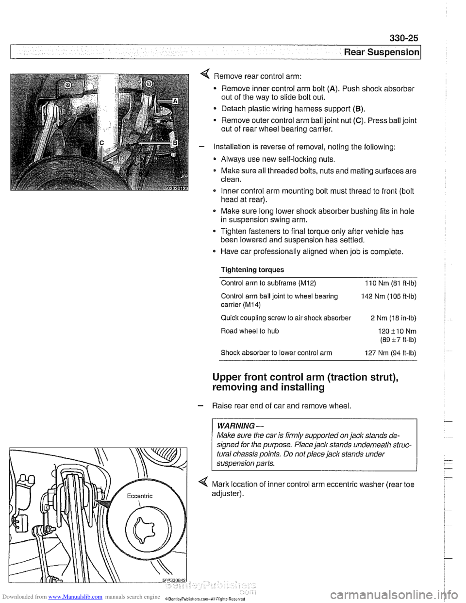
Remove rear control arm:
Remove inner control arm bolt
(A). Push shock absorber
out of the way to slide bolt out.
Detach plastic wiring harness support
(B).
Remove outer control arm ball joint nut (C). Press ball joint
out of rear wheel bearing carrier.
Installation is reverse of removal, noting the following:
* Always use new self-locking nuts.
Maite sure
ail threaded bolts, nuts and mating surfaces are
clean.
Inner control arm mounting bolt must thread to front
(bolt . head at rear).
Make sure long lower shock absorber bushing fits in hole
in suspension swing arm.
* Tighten fasteners to final torque only after vehicle has
been lowered and suspension has settled.
Have car professionally aligned when job is complete.
Tightening torques Control arm to
subframe (M12) 110 Nm (81 ft-ib)
Control arm ball joint to wheel bearing
142 Nm (105 ft-lb)
carrier
(M14)
Quick coupling screw to air shocit absorber
2 Nm (18 in-lb)
Road wheel to hub
Shoclc absorber to lower control arm 127 Nm (94 it-lb)
Upper front control arm (traction strut),
removing and installing
- Raise rear end of car and remove wheel.
WARNING-
Maice sure the car is firmly supported on jack stands de-
signed for the purpose. Place
jack stands underneath struc-
tural chassis points. Do not place jack stands under
< Mark location of inner control arm eccentric washer (rear toe
Page 771 of 1002
Downloaded from www.Manualslib.com manuals search engine
Brakes
Brakes, bleeding
The procedure below requires a BMW Service Tester (DIS-
pluslGTl/MoDiC).
- Determine type of traction control (ASC, DSC with precharge
pump, DSC without precharge pump). Be sure to use correct
specification brake fluid, according to application table below.
Brake fluid applications
ABS I ASC and ABS / DSC models DOT 4 brake fluid
with precharge pump (to 911998)
ABS I DSC models without precharge DOT 4 low viscosity
pump (911998 and later) brake
fluid
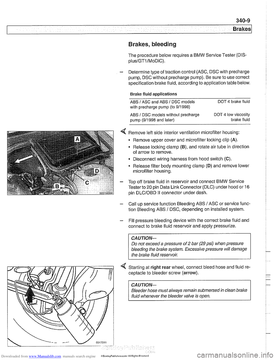
< Remove left side interior ventilation microfilter housing:
Remove upper cover and microfilter loclting clip
(A).
Release locking clamp (B), and rotate air tube in direction
of arrow to remove.
Disconnect wiring harness from hood switch
(C).
Release filter body mounting clamp (D) and remove lower
microfilter housing.
- Top off bralte fluid in reservoir and connect BMW Service
Tester to
20 pin Data Link Connector (DLC) under hood or 16
pin
DLCIOBD I1 connector under dash.
- Call up service function Bleeding ABS / ASC or service func-
tion Bleeding ABS
/ DSC, depending on installed system.
- Fill pressure bleeding device with the correct brake fluid and
connect to brake fluid reservoir and apply pressurize.
Do not exceed a pressure of
2 bar (29 psi) when pressure
bleeding the
brake system. Excessive pressure will damage
4 Starting at right rear wheel, connect bleed hose and fluid re-
ceptacle to bleeder screw (arrow).
CA UTlON-
Bleeder hose must always remain submersed in clean brake
fluid whenever the bleeder valve is open.