compression ratio BMW 530i 1997 E39 Workshop Manual
[x] Cancel search | Manufacturer: BMW, Model Year: 1997, Model line: 530i, Model: BMW 530i 1997 E39Pages: 1002
Page 99 of 1002
Downloaded from www.Manualslib.com manuals search engine
113-5
Cylinder Head Removal and Installation I
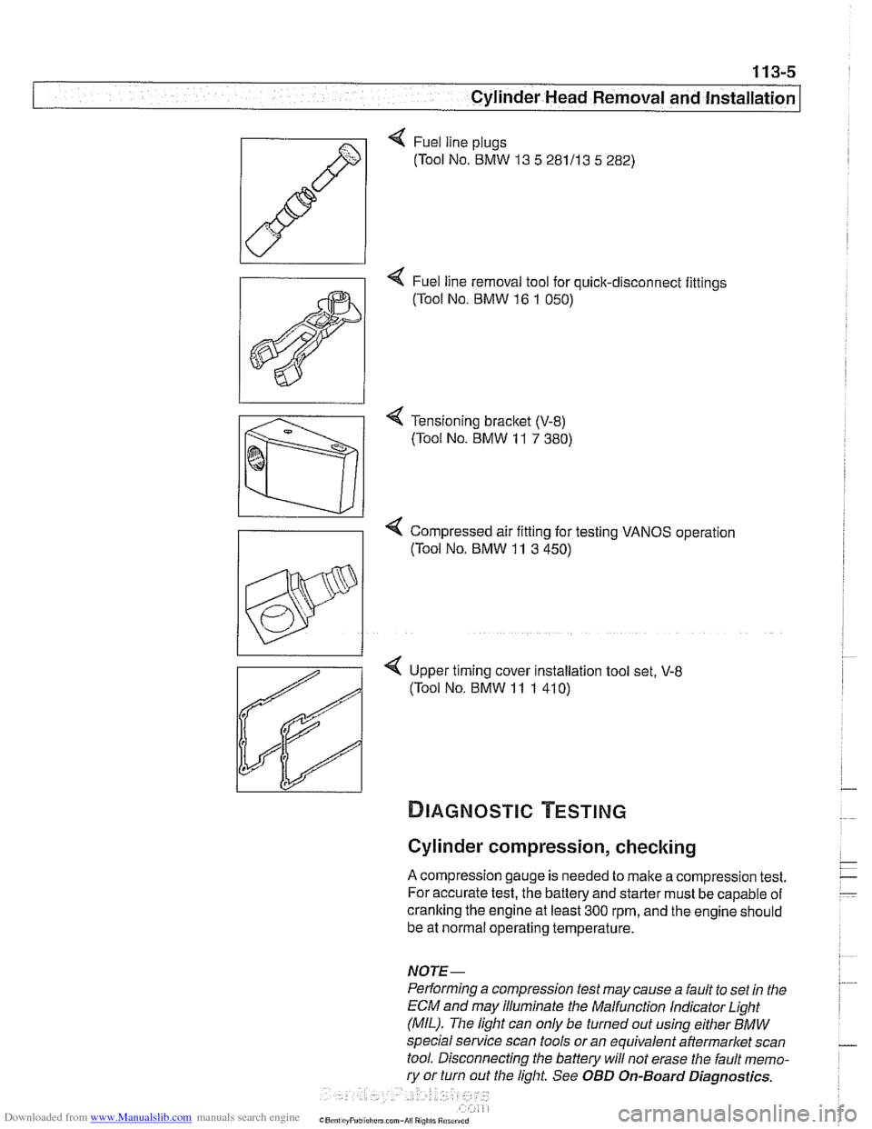
< Fuel line plugs
(Tool No.
BMW 13 5 281113 5 282)
4 Fuel line removal tool for quick-disconnect fittings
(Tool No.
BMW 16 1 050)
< Tensioning bracket (V-8)
(Tool No. BMW 11 7 380)
Compressed air fitting for testing VANOS operation
((Tool No.
BMW 11 3 450)
< Upper timing cover installation tool set, V-8
(Tool No. BMW 11 1 41 0)
Cylinder compression, checking
A compression gauge is needed to make a compression test.
For accurate test, the battery and starter must be capable of
cranking the engine at least
300 rpm, and the engine should
be at normal operating temperature.
NOTE-
Performing a compression test may cause a fault to set in the
ECM and may illuminate the Malfunction
Indicator Light
(MIL). The light can only be turned out using either
BMW
special service scan tools or an equivalent aftermarket scan
tool. Disconnecting the battery will not erase the fault memo-
ry or turn out the light. See OBD On-Board Diagnostics.
Page 351 of 1002
Downloaded from www.Manualslib.com manuals search engine
120-3
Ignition System
Warnings and cautions
The ignition system produces dangerous high voltage. In ad-
dition the sensitive electronic components can be damaged
if
proper precautions are not adhered to.
WARNING-
* Do not touch or disconnect any cables from the coils while
the engine is running or being
cranked by the starter.
The ignition system produces high voltages that can be
fatal. Avoid contact with exposed terminals. Use ex-
treme caution when working on a car with the ignition
switched on or the engine running.
- Connect and disconnect tlie DME system wiring and
test equipment leads only when the ignition is
OFF:
Before operating the starter without starting the engine
(for example when
making a compression test) always
disable the ignition.
CA
U TIOW-
Do not attempt to disable the ignition by removing the coils
from the spark plugs.
Connect or disconnect ignition system wires, multiple
wire connectors, and ignition test equipment leads only
while the ignition is
off Switch multimeter functions or
measurement ranges only with the test probes discon-
nected.
* Do not disconnect the battery while the engine is run-
ning.
A high impedance digital multimeter should be used for
all voltage and resistance tests. An LED test light
should be used in place of an incandescent-type test
lamp.
In general, make test connections only as specified by
BMW as described in this manual, or as described by
the instrument manufacturer.
Engine management
BMW €39 engines use an advanced engine management
system known as Digital Motor Electronics (DME). DME in-
corporates on-board diagnostics, fuel injection, ignition and
other engine control functions. DME variants are listed in
Table a. Engine management systems.
Second generation On-Board Diagnostics
(OED II) is incor-
porated into the engine management systems used on the
cars covered by this manual. Use a BMW-specific electronic
scan tool, or a "Generic"
OED II scan tool to access Diagnos-
tic Trouble Codes (DTCs). DTCs can help pinpoint ignition
ine management problems.
Page 355 of 1002
Downloaded from www.Manualslib.com manuals search engine
120-7
Ignition System
Spark plug electrode gap /Too small /TOO big
Table
b. Ignition secondary voltage diagnostics
Secondary
voltage low
Fuel air mixture
I I Too lean
Secondary
voltage high
Spark plug electrode
Worniburnt
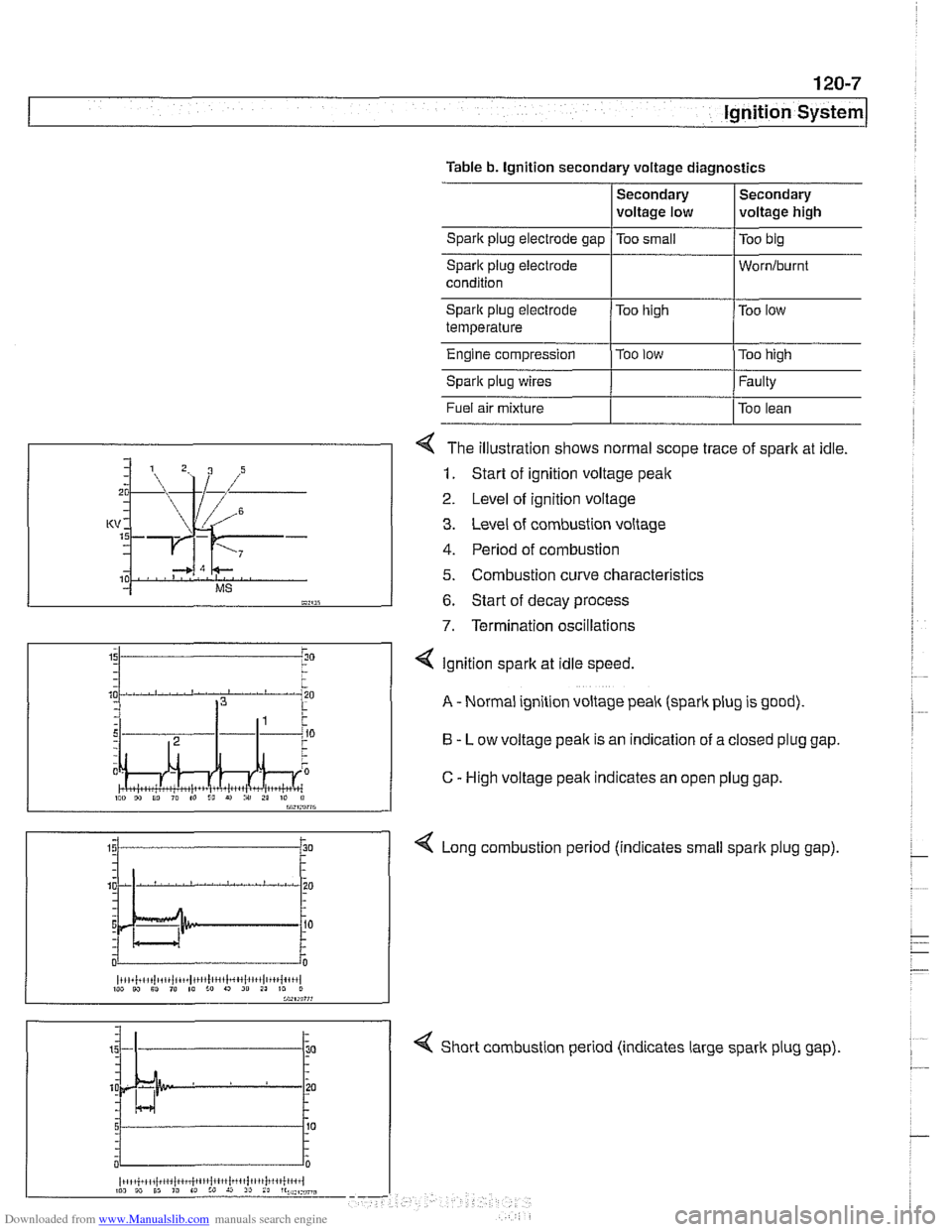
4 The illustration shows normal scope trace of spark at idle.
1. Start of ignition voltage peak
2 Level of ignition voltage
3. Level of combustion voltage
4. Period of combustion
5. Combustion curve characteristics
6. Start of decay process
7. Termination oscillations
Spark plug electrode
temperature
Engine compression
Spark plug wires
4 Short combustion period (indicates large spark plug gap).
Too
high
Too
low
I"" 9, 10 I" to I!, r) i" 21 10 il bW,rn?7G
Too low
Too high
Faulty
4 Ignition spark at idle speed.
A - Normal ignition voltage peak (spark plug is good).
B - Low voltage peak is an indication of a closed plug gap.
C
- High voltage peak indicates an open plug gap.
< Long combustion period (indicates small spark plug gap).
~i,+i!,~,i~tiii~iit~~,t1!lc,',l~~4~l~,~,l,~+~{+',,l 1W W Sl ,@ 10 :o 9 20 21 10 0
Page 357 of 1002
Downloaded from www.Manualslib.com manuals search engine
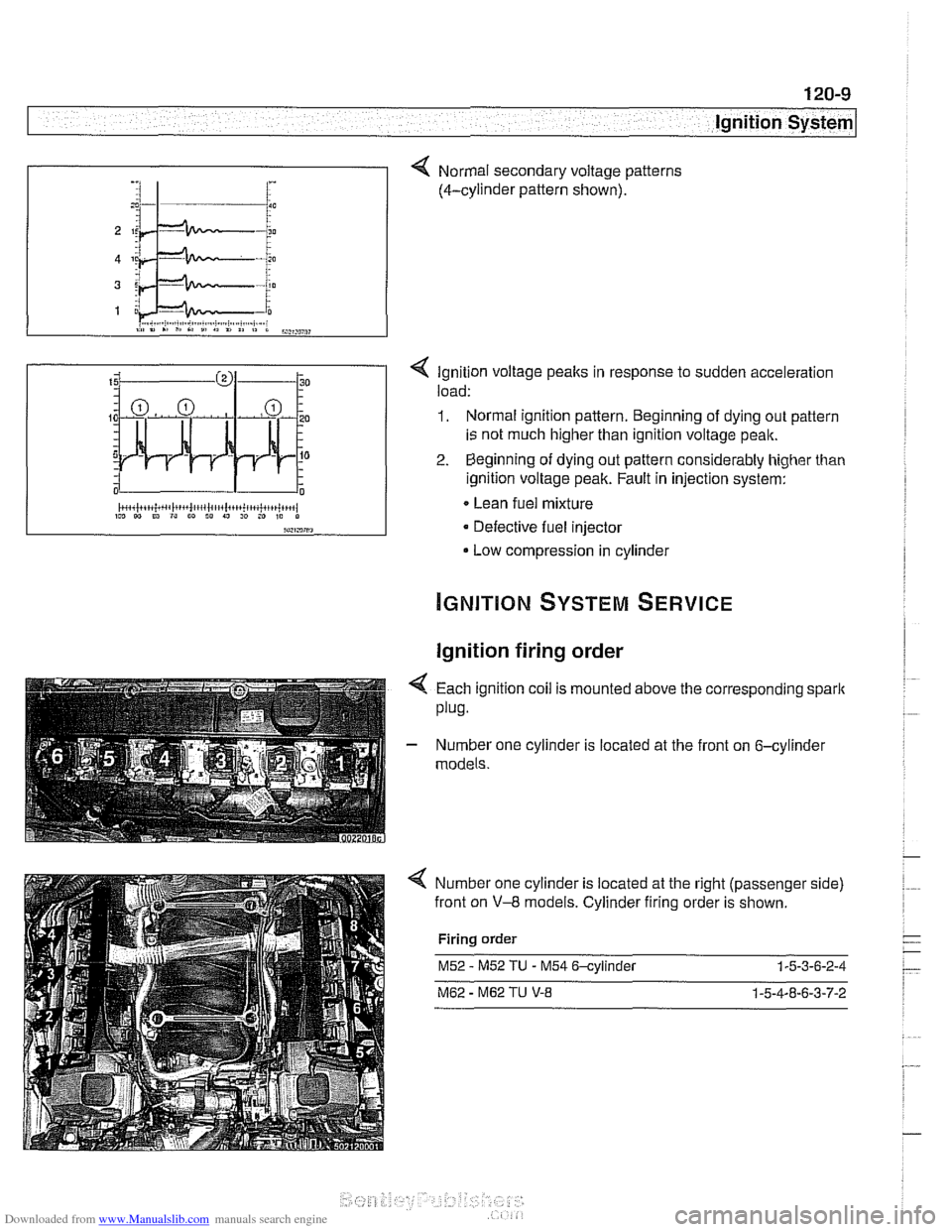
< Ignition voltage peaks in response to sudden acceleration
load:
1. Normal ignition pattern. Beginning of dying out pattern
is not much higher than ignition voltage peak.
2. Beginning of dying out pattern considerably higher than
ignition voltage peak. Fault in injection system:
Lean fuel mixture
Defective fuel injector
Low compression in cylinder
-, :I 1- i :
Ignition firing order
Normal secondary voltage patterns
(4-cylinder pattern shown).
4 Each ignition coil is mounted above the corresponding spark
plug.
- Number one cylinder is located at the front on 6-cylinder
models.
Number one cylinder is located at the right (passenger side)
front on
V-8 models. Cylinder firing order is shown.
Firing order
M52 - M52 TU - M54 6-cylinder 1-5-3-6-2-4
M62 - M62 TU V-8 1-5-4-8-6-3-7-2
Page 617 of 1002
Downloaded from www.Manualslib.com manuals search engine
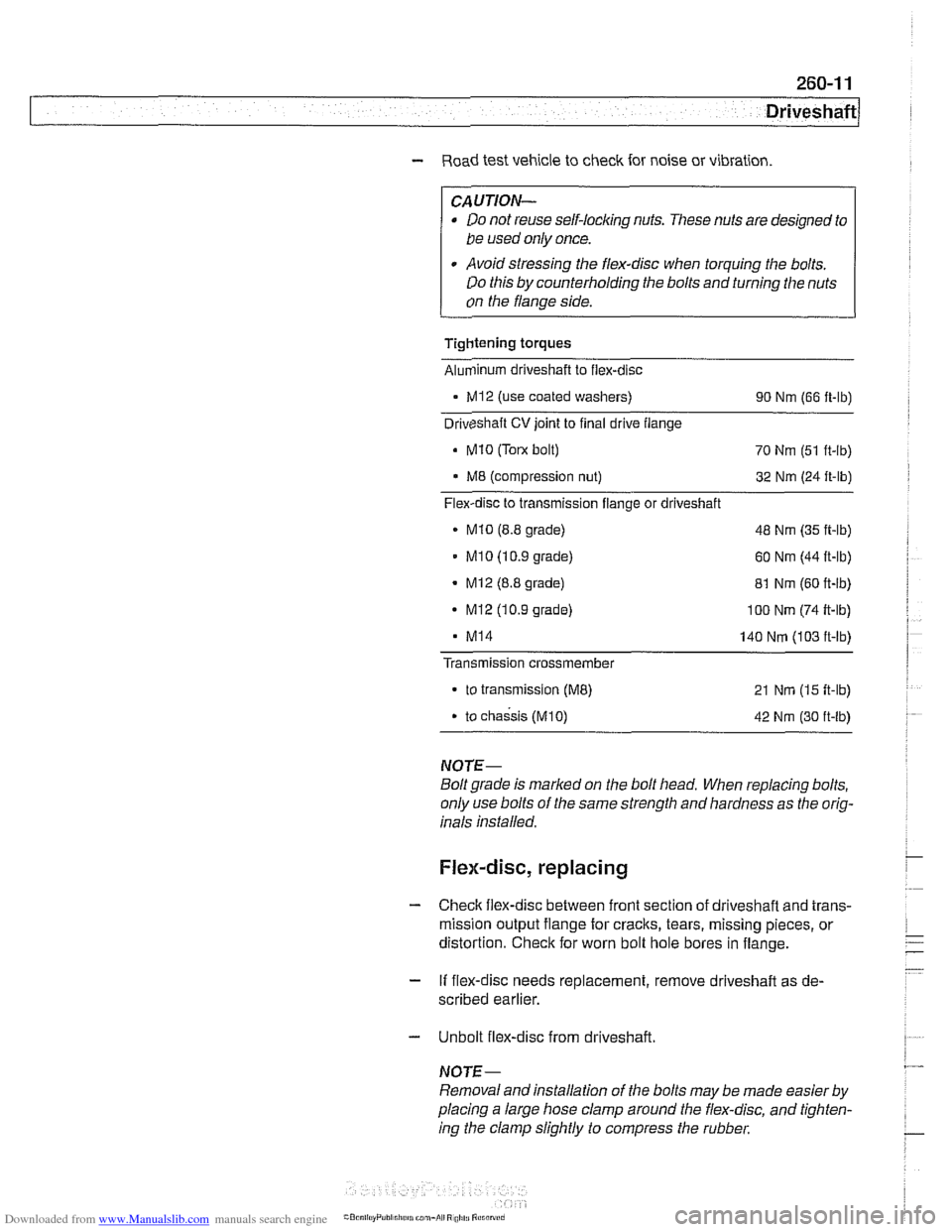
Driveshaft
- Road test vehicle to check for noise or vibration
CAUTION-
Do not reuse self-locking nuts. These nuts are designed to
be used only once.
Avoid stressing the flex-disc when torquing the bolts.
Do this by counterholding the bolts and turning the nuts
on the flange side.
Tightening torques
Alunlinum driveshaft to flex-disc
- MI2 (use coated washers)
90 Nm (66 ft-lb)
Driveshaft
CV joint to final drive flange
Mi0 (Tom bolt)
70 Nm (51 ft-lb)
M8 (compression nut) 32 Nm (24 ft-lb)
Flex-disc to transmission flange or driveshaft
MI0 (8.8 grade) 48 Nm (35 ft-lb)
MI 0 (1 0.9 grade) 60 Nm (44 ft-lb)
- Mi2 (8.8 grade)
81 Nm (60 ft-lb)
- MI2 (10.9 grade) I00 Nm (74 ft-lb)
MI4 140 Nm (103 ft-lb)
Transmission
crossmember
to transmission (ME) 21 Nm (15 ft-lb)
. to chassis (M10) 42 Nm (30 ft-lb)
NOTE-
Boltgrade is marked on the bolt head. When replacing bolts,
only use bolts of the same strength and hardness as the orig-
inals installed.
Flex-disc, replacing
- Checlc flex-disc between front section of driveshafl and trans-
mission output flange for craclts, tears, missing pieces, or
distortion. Check for worn bolt hole bores in flange.
- If flex-disc needs replacement, remove driveshafl as de-
scribed earlier.
- Unbolt flex-disc from driveshaft.
NOTE-
Removal andinstallation of the bolts may be made easier by
placing a large hose clamp around the flex-disc, and tighten-
ing the clamp slightly to compress the rubber.