fuse box diagram BMW 530i 1997 E39 Workshop Manual
[x] Cancel search | Manufacturer: BMW, Model Year: 1997, Model line: 530i, Model: BMW 530i 1997 E39Pages: 1002
Page 397 of 1002

Downloaded from www.Manualslib.com manuals search engine
Fuel Injection 1
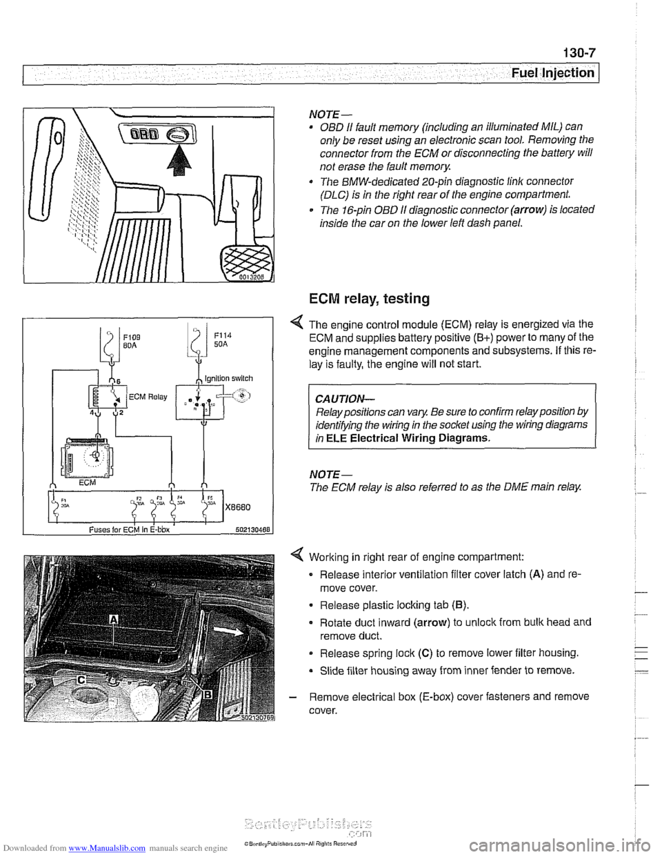
Working in right rear of engine compartment:
Release interior ventilation filter cover latch
(A) and re-
move cover.
Release plastic locking tab
(6).
Rotate duct inward (arrow) to unlock from bulk head and
remove duct.
Release spring
lock (C) to remove lower iilter housing.
Slide filter housing away from inner fender to remove.
- Remove electrical box (E-box) cover fasteners and remove
cover.
NOTE-
OBD I1 fault memory (including an illuminated MIL) can
only be reset using an electronic scan tool. Removing the
connector from the ECM or disconnecting the battery will
not erase the fault
memory.
The BMW-dedicated 20-pin diagnostic linlc connector
(DLC) is in the right rear of the engine compartment.
The 16-pin OBD
I1 diagnostic connector (arrow) is located
inside the car on the lower left dash panel.
ECM relay, testing
Fuses lor ECM In E-bbx 502130488
4 The engine control module (ECM) relay is energized via the
ECM and supplies battery positive
(B+) power to many of the
engine management components and subsystems.
If this re-
lay is faulty, the engine will not start.
Relay positions can vary. Be sure to confirm relay position by
identifying the wiring in the socket using the wiring diagrams
in
ELE Electrical Wiring Diagrams.
NOTE-
The ECM relay is also referred to as the DME main relay.
Page 398 of 1002

Downloaded from www.Manualslib.com manuals search engine
130-8
Fuel Injection
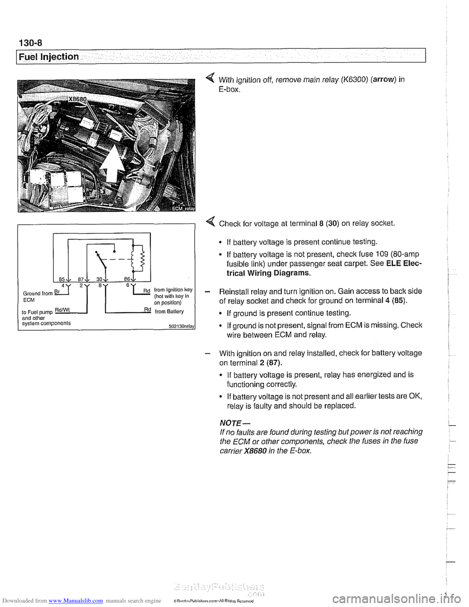
With ignition off, remove main relay (K6300) (arrow) in
E-box.
- With ignition on and relay installed, check for battery voltage
on terminal
2 (87).
4 Check for voltage at terminal 8 (30) on relay socket.
If battery voltage is present, relay has energized and is
functioning correctly.
Gmund from 6L (hot ~4th k~y key in Ern
2I '1
on position)
to
Fuel pump RdiWt Rd from Battery and other system components SOZI~O~~I~Y
If battery voltage is not present and all earlier tests are OK,
relay is faulty and should be replaced.
If
battery voltage is present continue testing.
If battery voltage is not present, check fuse 109 (80-amp
fusible link) under passenger seat carpet. See ELE Elec-
trical Wiring Diagrams.
- Reinstall relay and turn ignition on. Gain access to back side
of relay socket and check for ground on terminal
4 (85).
If ground is present continue testing.
If ground is not present, signal from ECM is missing. Check
NOTE-
If no faults are found during testing but power is not reaching
the
ECM or other components, check the fuses in the fuse
carrier
X8680 in the E-box.
wire
between ECM and relay.
Page 440 of 1002

Downloaded from www.Manualslib.com manuals search engine
130-50
Fuel Injection
Bosch M5.2
ECM relay
1 HoL al ail iirnel XOL a1 ail limes
i--[-----i F109 (BOA) electronics I L.$.....: .I:
ECM relay . . . . . . . . . ,
8,s
:,
6 1 .. ... ~~.~~. . ...... .-, Engine control ii~~-~.~~..~ ........ ~~~~~~.~~~~:. module relay -;I
Of?
,c,;,,,
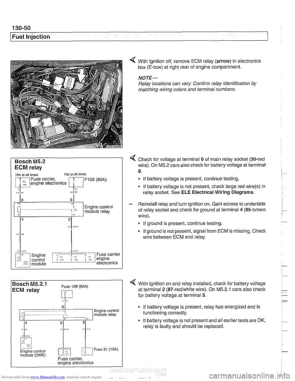
< With ignition off, remove ECM relay (arrow) in electronics
box (E-box) at right rear of engine compartment.
NOTE-
Relay locations can vary. Conh relay identification by
matcliing wiring colors and terminal numbers.
4 Check for voltage at terminal 6 of main relay socket (30-red
wire). On M5.2 cars also check for battery voltage at terminal
8.
. . . . . . . . . ,
If battery voltage is present, continue testing
.
If battery voltage is not present, check large red wire(s) in
relay socltet. See
ELE Electrical Wiring Diagrams.
%P,,tt
- Reinstall relay and turn ignition on. Gain access to underside
of relay socket and
checlc for ground at terminal 4 (85-brown
wire).
. . . . . . . . . . . . - - - - - - - - - . - - - . . l ,,-. ; Engine i f .: , ; Fuse carrier .,A . :engine /;is? /control L.!.!! .... 1.: ...... !.::..! I lij :module electronics If
ground is present, continue testing
If ground is not present, signal from ECM is missing. Checic
wire between ECM and relay.
4 With ignition on and relay installed, check for battery voltage
at terminal
2 (87-redlwhite wire). On M5.2.1 cars also checlc
for battery voltage at terminal 5.
If battery voltage is present, relay has energized and is
functioning correctly.
If battery voltage is not present and all earlier tests are OK,
relay is faulty and should be replaced.