spark plugs replace BMW 530i 1997 E39 Workshop Manual
[x] Cancel search | Manufacturer: BMW, Model Year: 1997, Model line: 530i, Model: BMW 530i 1997 E39Pages: 1002
Page 41 of 1002
Downloaded from www.Manualslib.com manuals search engine
--- -
Maintenance
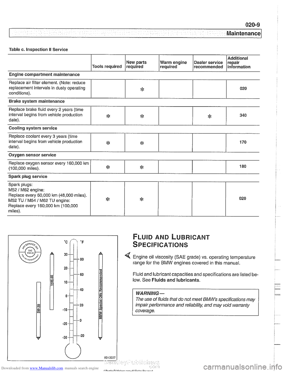
Table c. Inspection II Service
Additional
New parts Warm engine Dealer service repair
Tools required required required recommended information
Engine compartment maintenance
Replace air filter element. (Note: reduce
replacement intervals in dusty operating
conditions).
Replace brake
fluid every 2 years (time
interval begins from vehicle production
date).
Cooling system service
Spark plug service
Brake
system maintenance
:j:
*
Replace coolant every 3 years (time
interval begins from vehicle production
date).
Replace oxygen sensor every 160,000
itm
(1 00,000 miles).
020
FLUID AND LUBRICANT
SPECIFICATIONS
:I:
Oxygen sensor service
*
x:
Spark plugs:
M52
1 M62 engine:
Replace every 60,000 itm (48.000 miles).
M52
TU I M54 1 M62 TU engine:
Replace every 160,000
ltm (100.000
miles).
< Engine oil viscosity (SAE grade) vs. operating temperature
range for the BMW engines covered in this manual.
Fluid and lubricant capacities and specifications are listed be-
low. See
Fluids and lubricants.
:I:
*
*
*
WARNING -
The use of fluids that do not meet BMW" specifications may
impair performance and
reliabilitl: and may void warranty
coverage.
340
170
180
* 020
Page 52 of 1002
Downloaded from www.Manualslib.com manuals search engine
Maintenance
continue to operate as designed. Extending the replacement
interval may void the emission control warranty coverage.
See
180 Exhaust System for information on replacing the
oxygen sensors.
Tightening torque
Oxvoen sensor to exhaust
manifold 50 Nrn (37 ft-lb)
NOTE-
A special soclet for replacing the oxygen sensor is available
from most automotive parts stores. The soclet has
a groove
cut down one side to allow the sensor to be installed without
damaging the wire harness.
Power steering fluid, checking level
The power steering system is permanently filled and does not
have a drain. Routinely adding ATF is not required unless the
system is leaking.
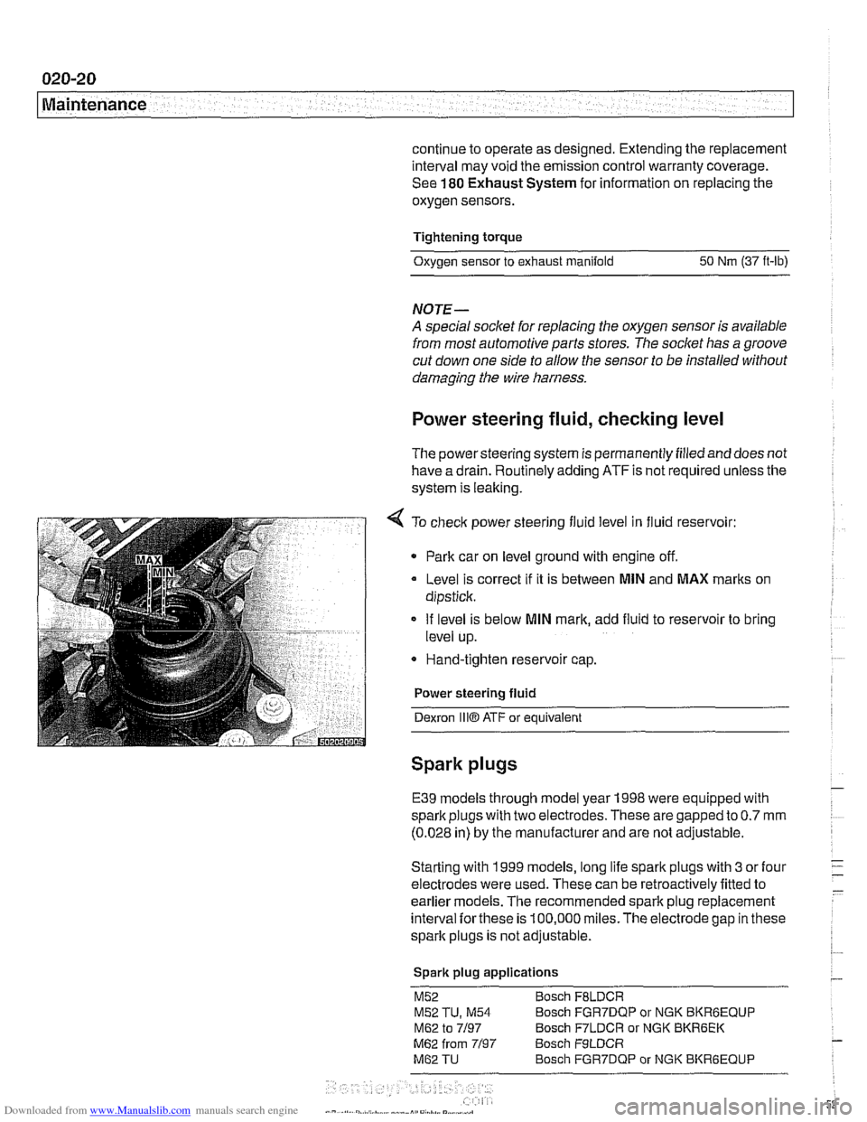
4 To check power steering fluid level in fluid reservoir:
Park car on level ground with engine off.
Level is correct
if it is between MlN and MAX marks on
dipstick.
If level is below
MlN mark, add fluid to reservoir to bring
level up.
* Hand-tighten reservoir cap.
Power steering fluid
Dexron
1iiO ATF or equivalent
Spark plugs
E39 models through model year 1998 were equipped with
spark plugs with two electrodes. These are gapped to
0.7 mm
(0.028 in) by the manufacturer and are not adjustable.
Starting with 1999 models, long life spark plugs with
3 or four
electrodes were used. These can be retroactively fitted to
earlier
models. The recommended spark plug replacement
interval
forthese is 100,000 miles.The electrode gap in these
spark plugs is not adjustable.
Spark plug applications
M52 Bosch FBLDCR
M52 TU, M54 Bosch FGR7DQP or NGK BKRBEQUP
M62 to 7/97 Bosch F7LDCR or NGK BKR6EK
M62 from 7/97 Bosch F9LDCR
M62 TU Bosch FGR7DQP or NGK BKRGEQUP
Page 54 of 1002
Downloaded from www.Manualslib.com manuals search engine
020-22 Maintenance
1
- Installation is reverse of removal, bearing in mind the
following:
Lightly lubricate new
spark plug threads with
copper-based anti-seize compound.
Thread plugs into cylinder head by hand to prevent
cross-threading.
. Be sure to reinstall and tighten coil grounds.
Tightening torque Spark plug
to cylinder head 25 Nm (18 It-lb)
Interior ventilation microfilter, replacing
Two interior ventilation microfilters are used, one on each
side of the engine compartment at the fire wall.
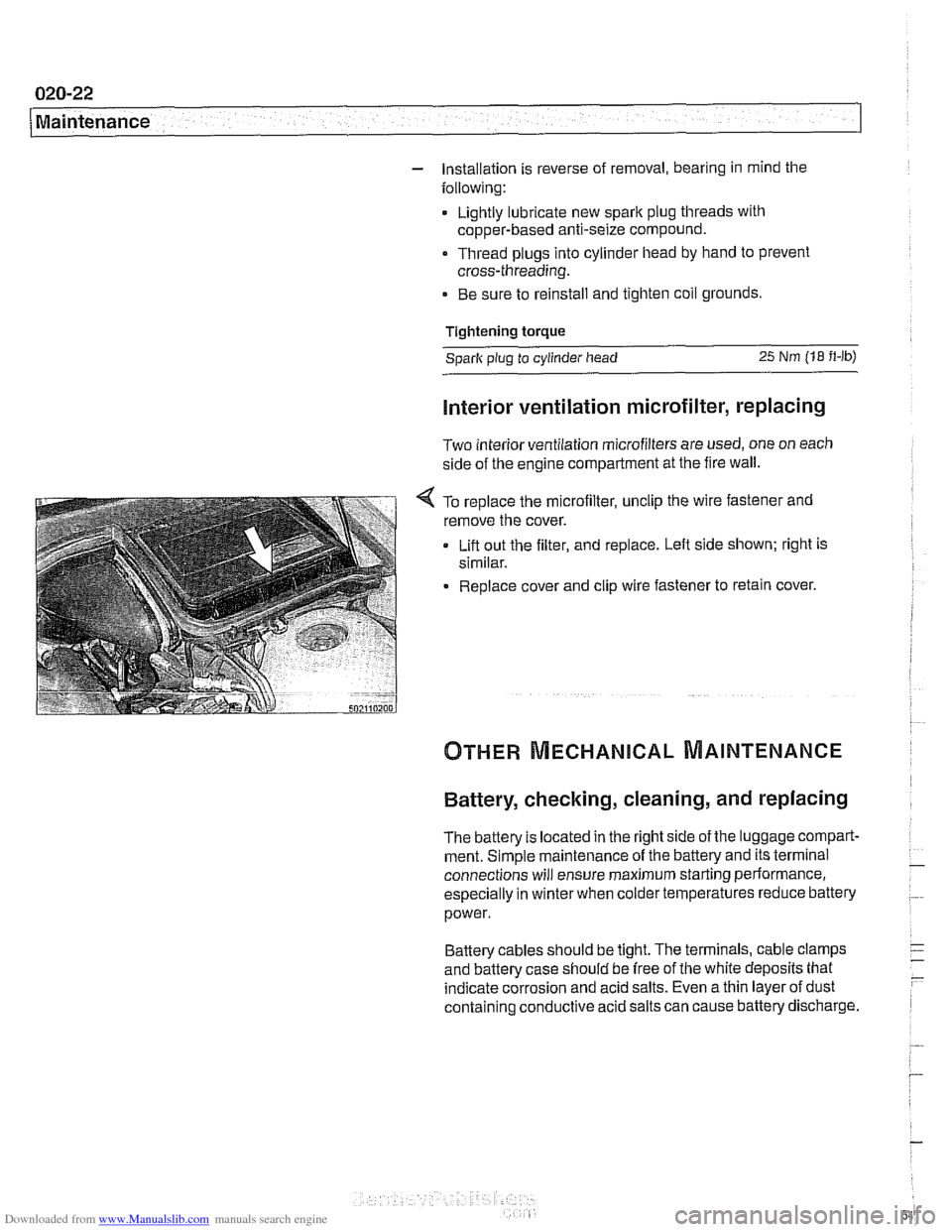
< To replace the microfilter, unclip the wire fastener and
remove the cover.
Lift out the filter, and replace. Left side shown; right is
similar.
Replace cover and clip wire fastener to retain cover.
Battery, checking, cleaning, and replacing
The battery Is located in the right side of the luggage compart-
ment. Simple maintenance of the battery and its terminal
connections will ensure maximum starting periormance,
especially in winter when colder temperatures reduce battery
power.
Battery cables should be tight. The terminals, cable clamps
and battery case should be free of the white deposits that
indicate corrosion and acid salts. Even a thin layer of dust
containing conductive acid salts can cause battery discharge.
Page 182 of 1002
Downloaded from www.Manualslib.com manuals search engine
11 6-6
Cylinder Head and Valvetrain
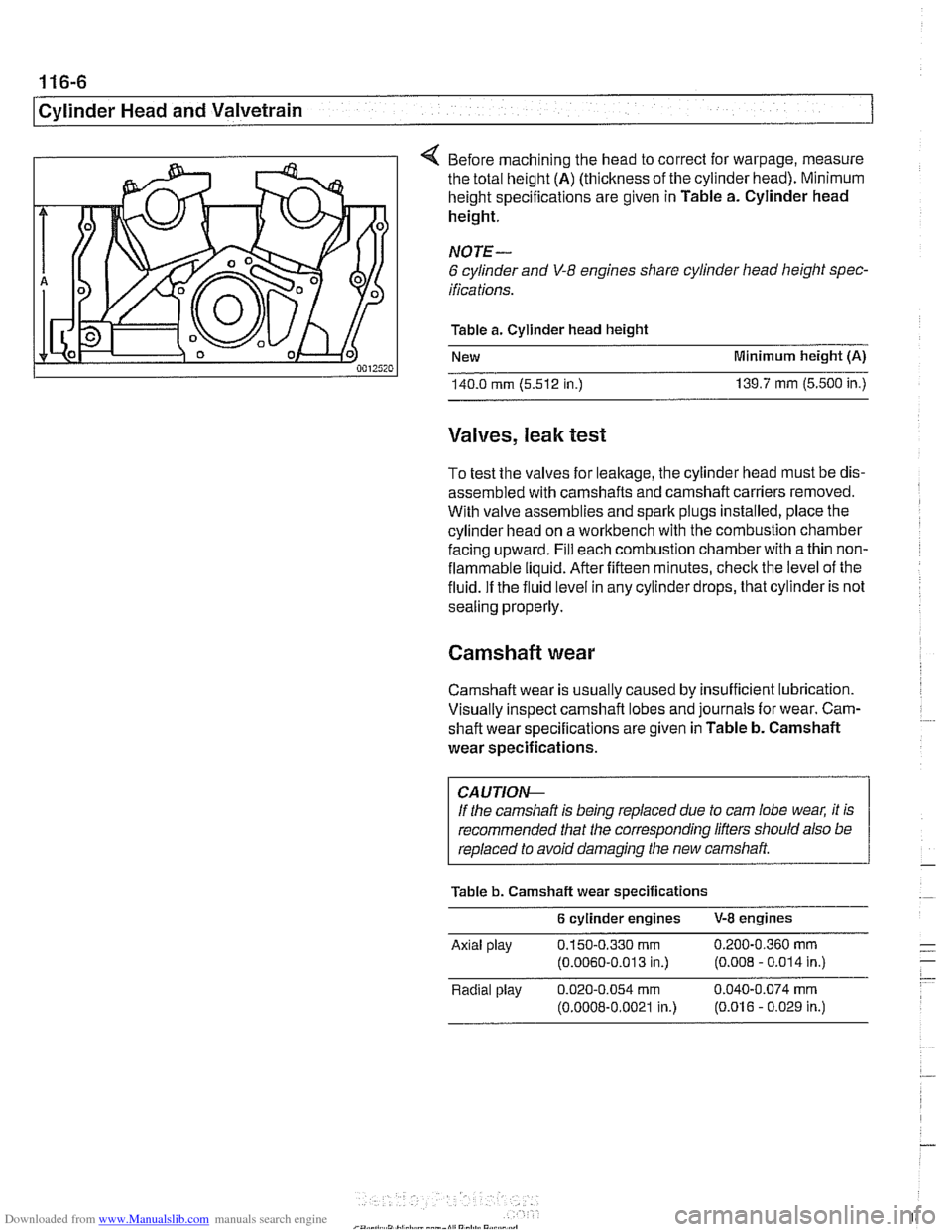
4 Before machining the head to correct for warpage, measure
the total height
(A) (thickness of the cylinder head). Minimum
height specifications are given in Table a. Cylinder head
height.
NOTE-
6 cylinder and V-8 engines share cylinder head height spec-
ifications.
Table a. Cylinder head height
New Minimum height
(A)
140.0 rnrn (5.512 in.) 139.7 rnrn (5.500 in.)
Valves, leak test
To test the valves for leakage, the cylinder head must be dis-
assembled with camshafts and camshaft carriers removed.
With valve assemblies and spark plugs installed, place the
cylinder head on a workbench with the combustion chamber
facing upward. Fill each combustion chamber with a thin non-
flammable liquid. After fifteen minutes, check the level of the
fluid. If the fluid level in any cylinder drops, that cylinder is not
sealing properly.
Camshaft wear
Camshaft wear is usually caused by insufficient lubrication.
Visually inspect camshaft lobes and journals for wear. Cam-
. ~~ shaft wear specifications are given in Table b. Camshaft
wear specifications.
CA UTIOI\C
If the camshaft is being replaced due to cam lobe wear, it is
recommended that the corresponding lifters should also be
replaced to avoid damaging the new camshaft
Table b. Camshaft wear specifications
6 cylinder engines V-8 engines
Axlal play 0.150-0.330 rnrn 0 200-0 360 rnrn - .-
(0.0060-0 013 in.) (0.008 - 0.014 in ) - - Radlal play 0.020-0.054 rnrn 0.040-0.074 rnrn
(0.0008-0.0021 in.) (0.016 - 0.029 in.)
Page 273 of 1002
Downloaded from www.Manualslib.com manuals search engine
Camshaft Timing Chain
VANOS control unit, removing
(M52 TU and M54 engines)
This procedure includes removal of the Double VANOS con-
trol unit.
NOTE-
If the Double VANOS control unit is being replaced, camshaft
timing must be checked. This procedure requires multiple
special tools. Be sure to read the procedures through before
beginning the repair.
- Working inside luggage compartment, disconnect negative
(-) battery cable.
Prior to disconnecting the
batteg read the battery discon-
nection cautions given in
001 General Cautions and
Remove engine cooling fan assembly. See 170 Radiator
and Cooling System.
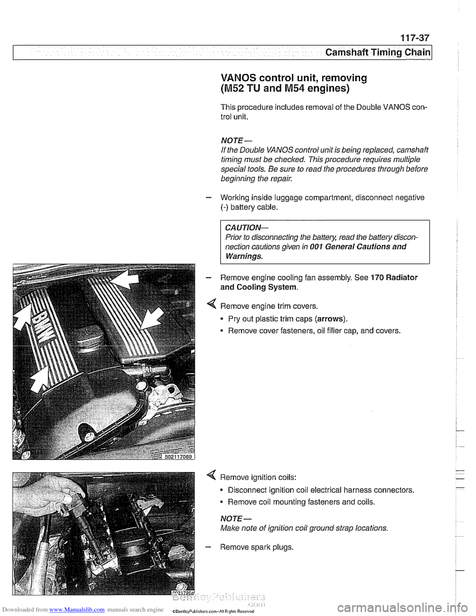
Remove engine trim covers.
Pry out plastic trim caps (arrows).
Remove cover fasteners, oil filler cap, and covers.
Remove ignition coils:
Disconnect ignition coil electrical harness connectors.
Remove coil mounting fasteners and coils.
NOTE-
Make note of ignition coil ground strap locations.
Remove spark plugs,
Page 279 of 1002
Downloaded from www.Manualslib.com manuals search engine
Camshaft Timing Chain
- Connect electrical harness connectors to camshaft position
sensors and VANOS solenoid valves.
- Remove BMW special locking tools from rear of cylinder
head.
- Remove cranltshaft locking tool and replace sealing plug.
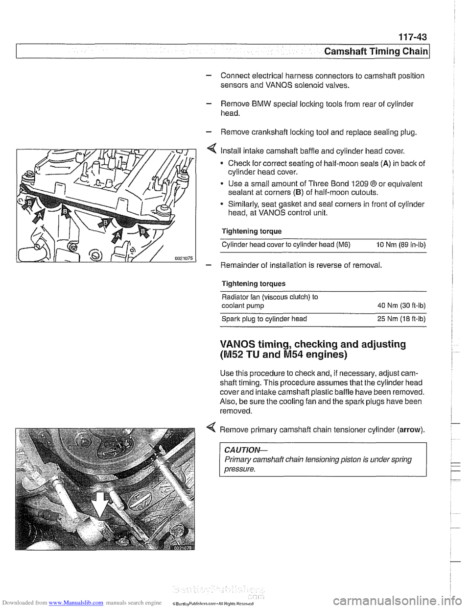
Install intake camshaft baffle and cylinder head cover.
Checlc for correct seating of half-moon seals (A) in back of
cylinder head cover.
Use a small amount of Three Bond 1209
O or equivalent
sealant at corners
(B) of half-moon cutouts.
Similarly, seat gasket and
seal corners in front of cylinder
head, at VANOS control unit.
Tightening torque
Cylinder head cover to cylinder head
(M6) 10 Nm (89 in-lb)
- Remainder of installation is reverse of removal.
Tightening torques
Radiator fan (viscous clutch) to
coolant pump 40
Nm (30 ft-lb)
Spark plug to cylinder head
25 Nrn (18 ft-lb)
VANOS timing, checking and adjusting
(M52 TU and M54 engines)
Use this procedure to check and, if necessary, adjust cam-
shaft timing. This procedure assumes that the cylinder head
cover and intake
camshaft plastic baffle have been removed.
Also, be sure the cooling fan and the spark plugs have been
removed.
Remove primary camshaft chain tensioner cylinder
(arrow).
~~ ~ ~~ ~--~
CA UTlOAC
Primary camshaft chain tensioning piston is under spring
pressure.
Page 358 of 1002
Downloaded from www.Manualslib.com manuals search engine
.-
ignition System
Disabling ignition system
The ignition system operates in a lethal voltage range and
should be disabled any time engine service or repair work is
being done that requires the ignition to be switched on.
The engine management system can be disabled by remov-
ing the DME main relay. The relay is located in the electronics
box (E-box) in the left rear of the engine
compartment, be.
neath the interior microfilter housing.
CAUTION- Relay locations may
vary. Use care when identifying relays.
See
610 Electrical Component Locations.
Checking for spark
CAUTION-
If
a spark test is done incorrecth damage to the Engine Con-
trol Module
(ECM) or the ignition coils may result.
NOTE-
Spark plug replacement is covered in 020 Maintenance.
Check~ng for spark is d~fflcult on englnes wlth d~str~butorless
ignition systems.
Try removing the spark plugs and inspecting for differences between them.
A poor-firing plug may be wet with fuel and/or ~. - ~
black and sooty, but not always. If a coil is not operating, the
engine management system will electrically disable the fuel
injector to that cylinder. The key is to look for differences be-
tween cylinders.
Ignition coil assembly, testing and
replacing
C4 UTION-
Use a digital multimeter for the following tests. I
- Remove plastic engine cover from top of valve cover by pry-
ing off bolt covers and removing cover mounting bolts.
- Raise car slowly while constantly checking position of jack
and car.
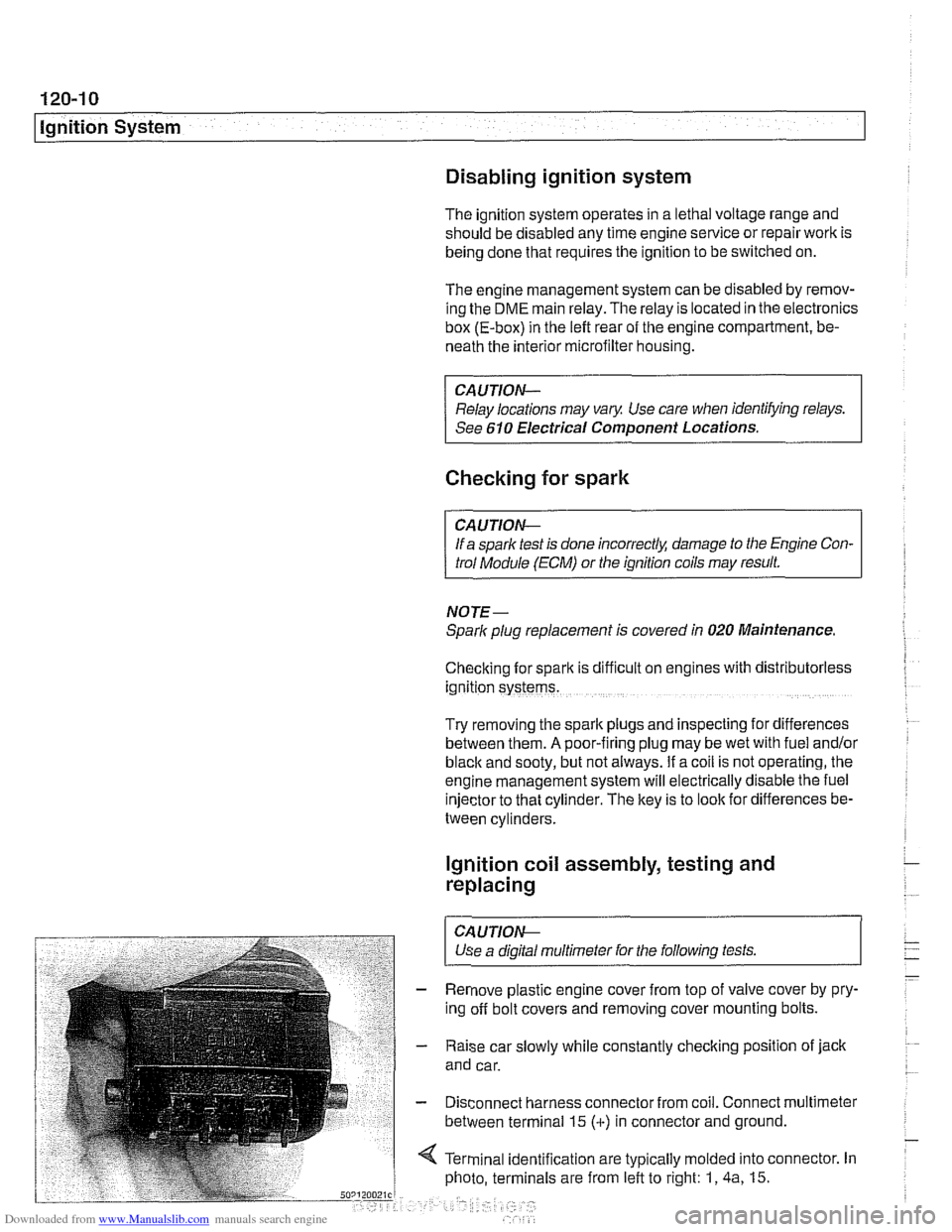
- Disconnect harness connector from coil. Connect multimeter
between terminal 15
(+) in connector and ground.
4 Terminal identification are typically molded into connector. In
photo, terminals are from left to right: 1,
4a, 15.