window BMW 530i 1997 E39 Workshop Manual
[x] Cancel search | Manufacturer: BMW, Model Year: 1997, Model line: 530i, Model: BMW 530i 1997 E39Pages: 1002
Page 3 of 1002
Downloaded from www.Manualslib.com manuals search engine
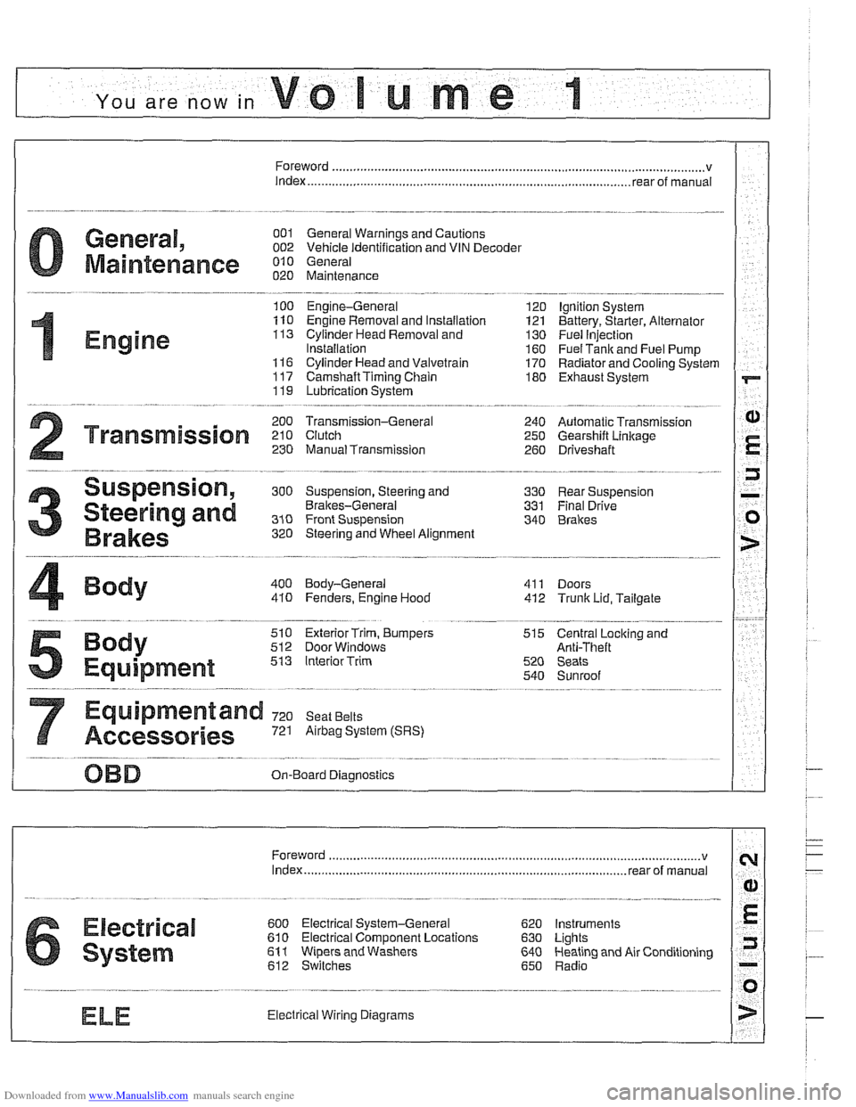
YOU are now in Volume I
I
Foreword ................... .. ........................................................................\
.......... v
Index
........................ .. ................................................................ rear of manual
General, 001 General Warnings and Cautions 002 Vehicle Identification and VIN Decoder
Maintenance OiO 020 Maintenance
Engine
100 Engine-General 110 Engine Removal and Installation
113 Cylinder Head Removal and
Installation
116 Cyiinder Head and Valvetrain 117 Camshaft Timing Chain
119 Lubrication System
200 Transmission-General
2 Transmission 210 clutch 230 ManualTransmission
I20 Ignition System
121 Battery, Starter, Alternator
130 Fuel Injection
160 Fuel Tank and Fuel Pump 170 Radiator and Cooling System
180 Exhaust System
240 Automatic Transmission
250 Gearshift Linkage 260 Driveshaft
Suspension, 300 Suspension, Steering and 330 Rear Suspension
Brakes-General 331 Final Drive
Steering and No Front Suspension 340 Brakes
320 Steering and Wheel Alignment
400 Body-General
410 Fenders, Engine Hood 411 Doors
412 Trunk Lid, Tailgate
510 Exterior Trim, Bumpers 512 Door Windows
Equipment 513 Interior Trim
7
Equipment and 720 seat Belts
Accessories 721 Airbag System (SRS)
OBD On-Board Diagnostics
. ............ ..
515 Central Lociting and
Anti-Theft
520 Seats 540 Sunroof
.................................................................... Foreword .............................. .. v
Index ................... .. ................................................................ rear of manual
Electrical
6 system
600 Electrical System-General 620 Instruments
610 Electrical Comoonent Locations 630 Liohts
611 wipers and washers 612 Switches eati in^ and Air Conditioning
Radio
. ........... ........ .........................
Electrical Wiring Diagrams
Page 380 of 1002
Downloaded from www.Manualslib.com manuals search engine
- -
/Battery, Starter, Alternator -- - -. - --I
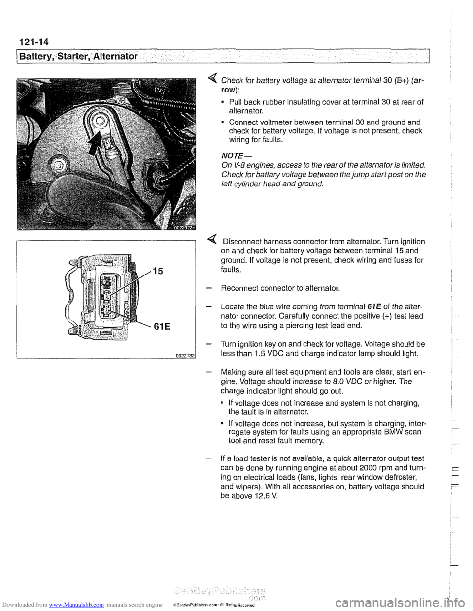
< Check for battery voltage at alternator terminal 30 (B+) (ar-
row):
Pull back rubber insulating cover at terminal 30 at rear of
alternator.
Connect voltmeter between terminal 30 and ground and
check for battery voltage.
If voltage is not present, check
wiring for faults.
NOTE-
On V-8 engines, access to the rear of the alternator is limited.
Check for battery voltage between the jump start post on the
left cylinder head and ground.
r Disconnect harness connector from alternator. Turn ianition
on and check for battery voltage between terminal
lgand
ground. If voltage is not present, check wiring and fuses for
faults.
Reconnect connector to alternator.
Locate the blue wire coming from terminal
61E of the alter-
nator connector. Carefully connect the positive
(+) test lead
to the wire using a piercing test lead end.
Turn ignition key on and check for voltage. Voltage should be
less than 1.5 VDC and charge indicator lamp should light.
- Making sure all test equipment and tools are clear, start en-
gine. Voltage should increase to
8.0 VDC or higher. The
charge indicator light should go out.
If voltage does not increase and system is not charging,
the fault is in alternator.
- If voltage does not increase, but system is charging, inter- - roaate svstem for faults usina an appropriate BMW scan - .. . tool and'reset fault memory.
- If a load tester is not available, a quick alternator output test
can be done by running engine at about 2000 rpm and turn-
- -
ing on electrical loads (fans, lights, rear window defroster, -
- and wipers). With all accessories on, battery voltage should
be above 12.6
V.
Page 701 of 1002
Downloaded from www.Manualslib.com manuals search engine
330-5
Rear Suspension
REAR STRUTS AND SPRINGS
(SEDAN MODELS)
Rear strut assembly, removing and
installing
Replace struts and coil springs in pairs only.
- Raise car and remove rear wheels.
WARNING -
Male sure the car is firmly supported on jack stands de-
signed for the purpose. Place jack stands underneath struc-
tural chassis points. Do not place jack stands under
suspension parts.
- Remove rear parcel shelf:
Remove rear seat headrests by pulling straight up.
Remove both rear roof pillar (C-pillar) trim panels.
Unbolt rear seat
belt anchors. See 720 Seat Belts.
Models with fixed rear seat: Remove rear seat backrest.
See 520 Seats.
* Models with fold-down rear seat: Remove rear seat back-
rest side sections. See 520 Seats. Fold down backrest.
* Working inside trunk, remove roller blind mounting nuts
and bolts, if applicable. Also disconnect roller blind har-
ness connector at right edge of rear seat backrest.
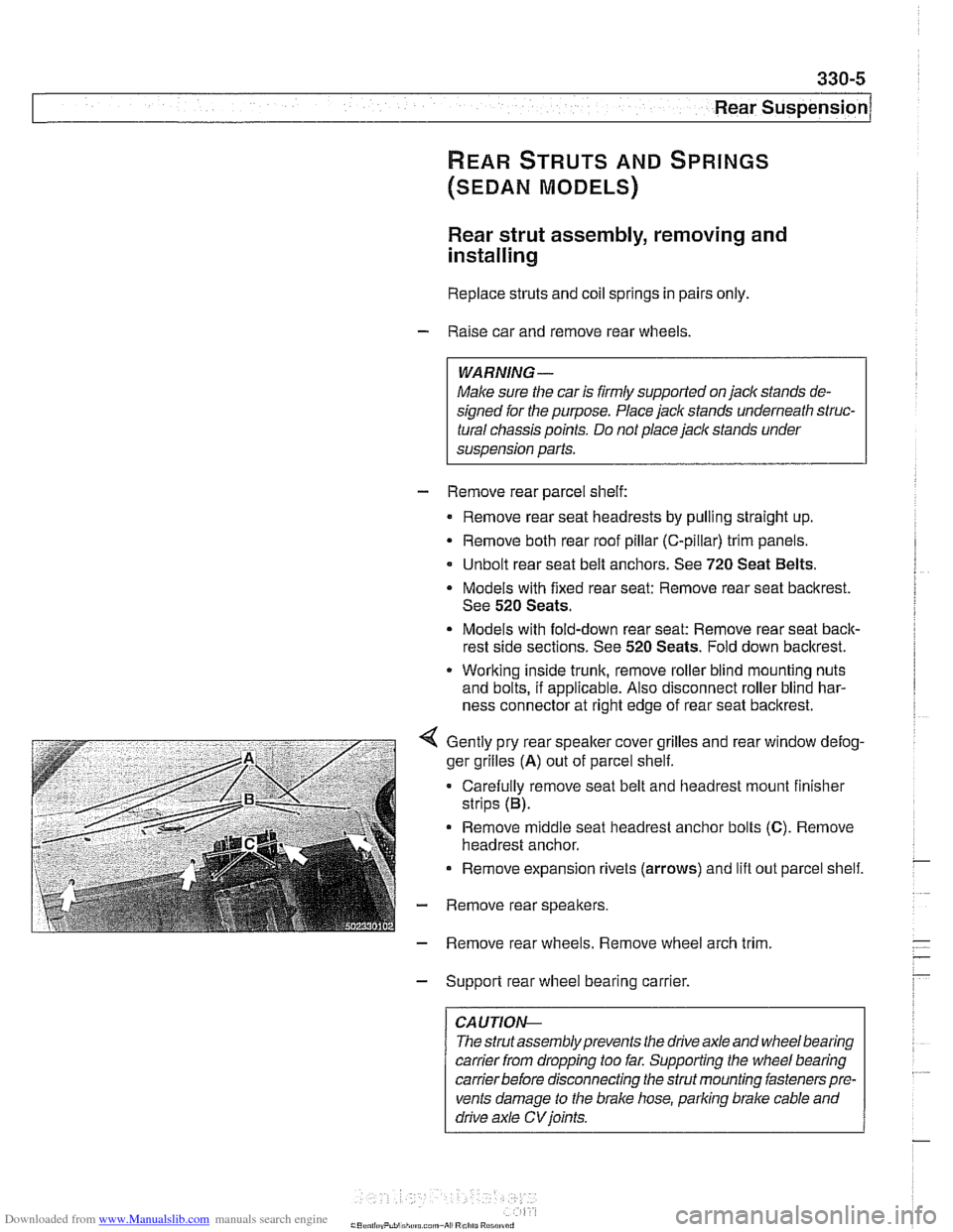
Gently pry rear speaker cover grilles and rear window defog-
ger grilles
(A) out of parcel shelf.
Carefully remove seat belt and headrest mount finisher
strips (B).
Remove
middle seat headrest anchor bolts (C). Remove
headrest anchor.
Remove expansion rivets (arrows) and lift out parcel shelf.
- Remove rear speakers.
- Remove rear wheels. Remove wheel arch trim
- Support rear wheel bearing carrier.
CAUTION-
The strutassembly prevents the drive axle and wheel bearing
carrier
from dropping too far. Supporting the wheel bearing
carrierbefore disconnecting the strut mounting fasteners pre-
vents damage to the brake hose, parking brake cable and
drive axle
CV joints.
Page 797 of 1002
Downloaded from www.Manualslib.com manuals search engine
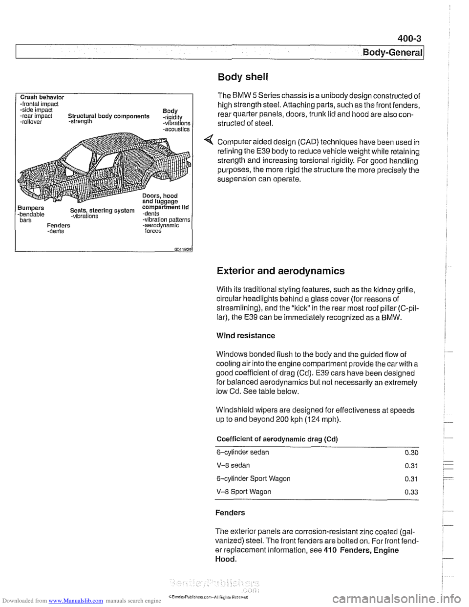
Body shell
Exterior and aerodynamics
Crash behavlor -frontal impact
-side impact
Body
-rear impact Structural body components -rigidity
-rollover -strength -vibrations -acoustics
Bumpers compartment lid -bendable Seets,.steerlng system .dents -vibrations bars -vibration patterns
Fenders -aerodvnamic
With its traditional styling features, such as the ltidney grille.
circular headlights behind a glass cover (for reasons of
streamlining), and the
"kiclt" in the rear most roof pillar (C-pil-
lar), the E39 can be immediately recognized as a BMW.
The BMW 5 Series chassis is a unibody design constructed of
high strength steel. Attaching parts, such as the front fenders,
rear quarter panels, doors,
trunk lid and hood are also con-
structed of
steel.
Computer aided design (CAD) techniques have been used in
refining the
E39 body to reduce vehicle weight while retaining
strength and increasing torsional rigidity. For good handling
purposes, the more rigid the structure the more precisely the
suspension can operate.
Wind resistance
Windows bonded flush to the body and the guided flow of
cooling air into the engine compartment provide the
carwith a
good coefficient of drag (Cd).
E39 cars have been designed
for balanced aerodynamics but not necessarily an extremely
low Cd. See table below.
Windshield wipers are designed for effectiveness at speeds
up to and beyond 200
ltph (124 mph).
Coefficient of aerodynamic drag (Cd)
6-cylinder sedan 0.30
V-8 sedan 0.31
6-cylinder Sport Wagon 0.31
V-8 Sport Wagon 0.33
Fenders
The exterior panels are corrosion-resistant zinc coated (gal-
vanized) steel. The front fenders are bolted on. For front fend-
er replacement information, see
410 Fenders, Engine
Hood.
Page 799 of 1002
Downloaded from www.Manualslib.com manuals search engine
400-5
Body-General
Tailgate
The E39 Sporl Wagon tailgate is large with a low sill for easy
cargo loading. The tailgate opens to an angle of
88" mea-
sured from the rear roof pillar (D-pillar) and to a height of
2029
mm (79.8 in) measured from the ground to the upper edge of
the raised tailgate.
The rear window is bonded to a load bearing frame and can
be opened separately from the main tailgate. Tailgatesupport
gas springs are recessed into cavities in the roof.
Tailgate lock system
A mechanical tailgate lock cylinder is not used; the tailgate is
opened by the unlock pad above the license plate, the remote
tailgate switch located in the drivers kick panel, or via
FZV
(Iteyless entry) control.
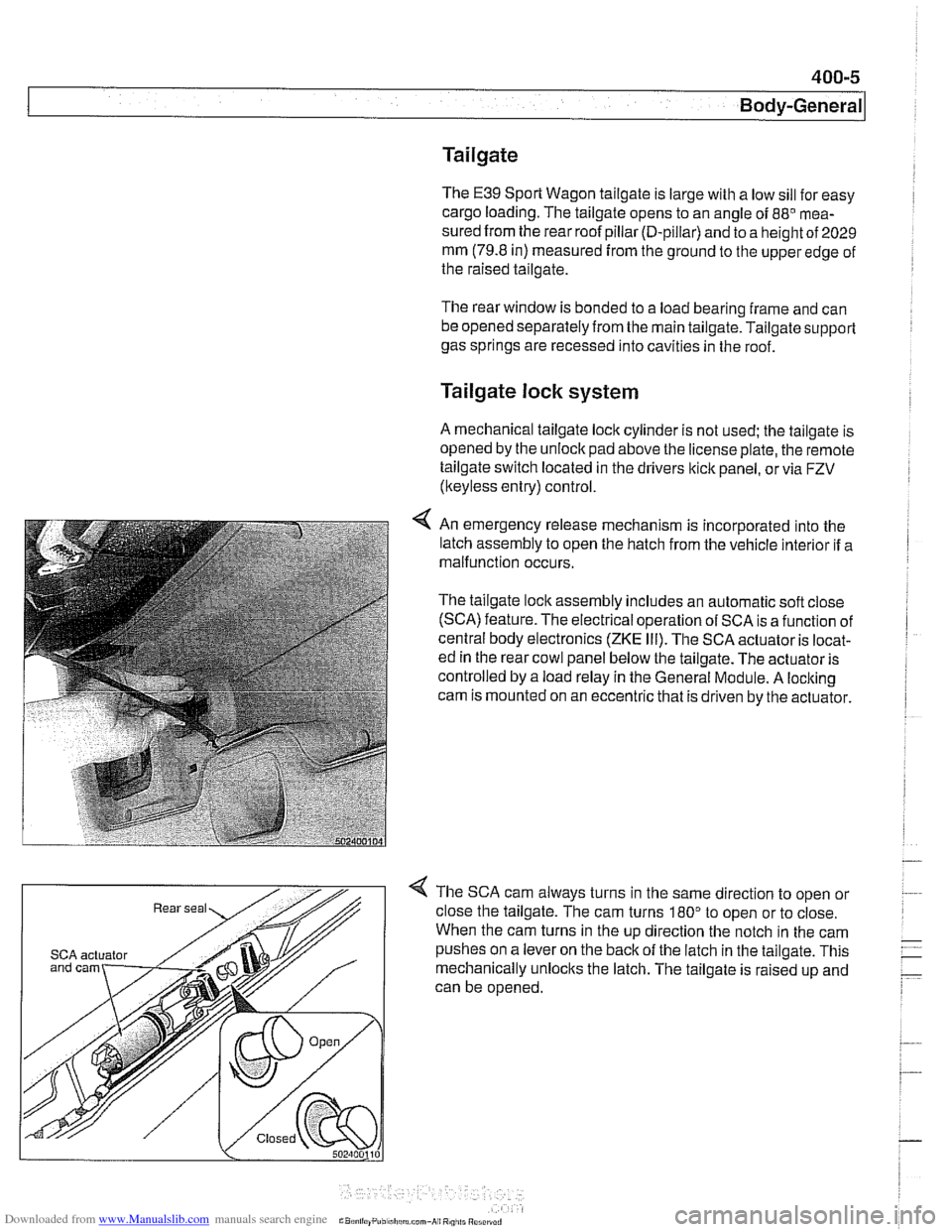
4 An emergency release mechanism is incorporated into the
latch assembly to open the hatch from the vehicle interior if a
malfunction occurs.
The tailgate lock assembly includes an automatic soft close
(SCA) feature. The electrical operation of SCA is a function of
central body electronics
(ZKE Ill). The SCA actuator is locat-
ed in the rear cowl panel below the tailgate. The actuator is
controlled by a load relay in the General Module. A locking
cam is mounted on an eccentric that is driven by the actuator.
4 The SCA cam always turns in the same direction to open or
close the tailgate. The cam turns
180" to open or to close.
When the cam turns in the up direction the notch in the cam
SCA actuator pushes on a lever on the back of the latch in the tailgate. This
mechanically unlocks the latch. The tailgate is raised up and
can be opened.
Page 800 of 1002
Downloaded from www.Manualslib.com manuals search engine
.
I Body-General 1
Rear wiper system
The rear wiper assembly on the E39 Sport Wagon is a self-
contained unit. The control electronics are integrated into the
gear drive that is part of the motor assembly. The control elec-
tronics contain two hall sensors, one
forthe park position and
one
forthe end stop or to signal reverse direction of the wiper
motor.
-
Wiperlwasher
stalk switch
/ 4 - 3
502400100
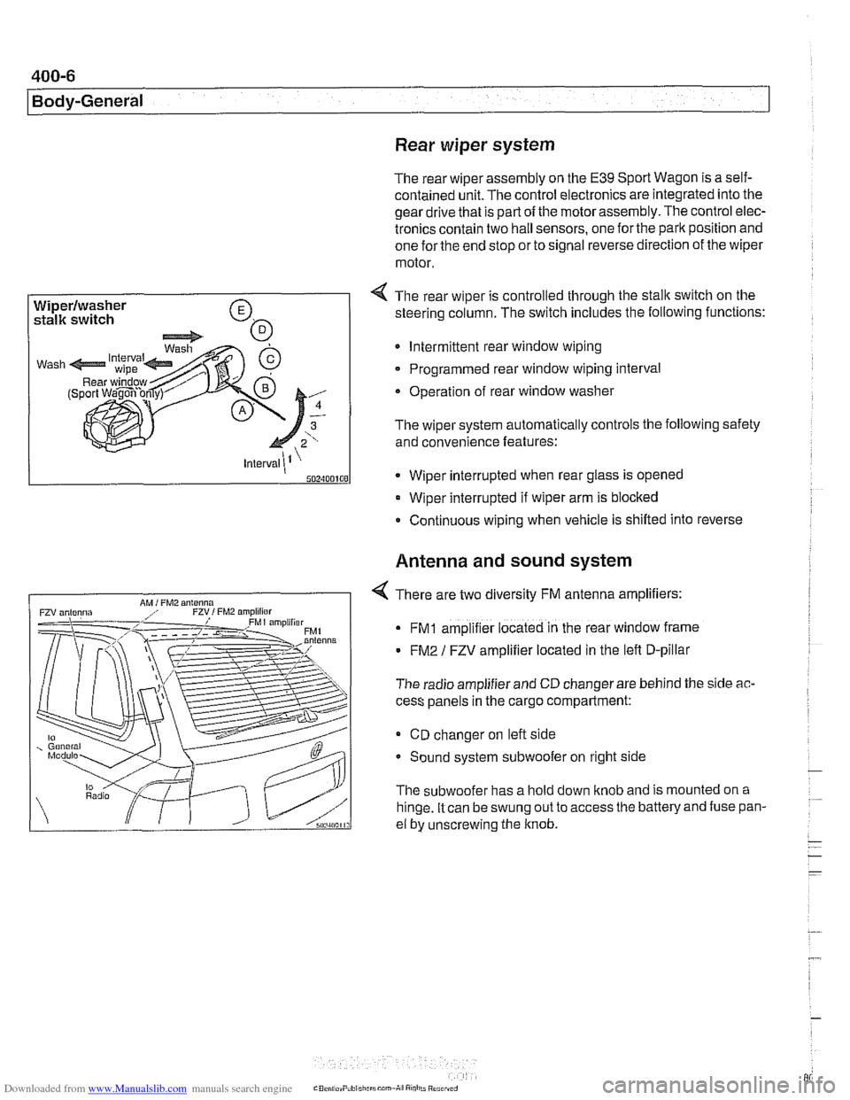
4 The rear wiper is controlled through the stalk switch on the
steering column. The switch includes the following functions:
Intermittent rear window wiping
Programmed rear window wiping interval
Operation of rear window washer
The wiper system automatically controls the following safety
and convenience features:
* Wiper interrupted when rear glass is opened
Wiper interrupted if wiper arm is blocked
Continuous wiping when vehicle is shifled into reverse
Antenna and sound system
4 There are two diversity FM antenna amplifiers:
FMI amplifier located in the rear window frame
FM2 / FZV amplifier located in the lefl D-pillar
The radio amplifier and CD changer are behind the side
ac-
cess panels in the cargo compartment:
CD changer on lefl side
Sound system subwoofer on right side
The subwoofer has a hold down knob and is mounted on a
hinge. It can be swung out to access
the batteryand fuse pan-
el by unscrewing the knob.
Page 803 of 1002
Downloaded from www.Manualslib.com manuals search engine
400-9
Body-General
Battery safety terminal
(BST)
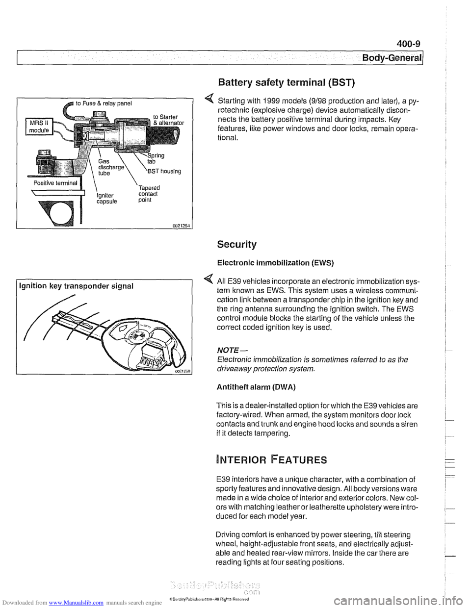
4 Starting with 1999 models (9198 production and later), a py-
rotechnic (explosive charge) device automatically discon-
nects the battery positive terminal during impacts. Key
features,
like power windows and door locks, remain opera-
tional.
Security
Electronic immobilization (EWS)
Ignition key transponder signal All
E39 vehicles incorporate an electronic immobilization sys-
tem known as EWS. This svstem uses a wireless comrnuni-
cation link between a transponder chip in the ignition key and
the ring antenna surrounding the ignition switch. The EWS
control module blocks the starting of the vehicle unless the
correct coded ignition key is used.
NOTE-
Electronic immobilization is sometimes referred to as the
driveaway protection system.
Antitheft alarm (DWA)
This is adealer-installed option for which the E39 vehicles are
factory-wired. When armed, the system monitors door
loci(
contacts and trunk and engine hood locks and sounds a siren
if it detects tampering.
E39 interiors have a unique character, with a combination
of
sporty features and innovativedesign. All body versions were
made in a wide choice of interior and exterior colors. New col-
ors with matching leather or leatherette upholstery were intro-
duced for each model year.
Driving
comfort is enhanced by power steering, tilt steering
wheel, height-adjustable front seats, and electrically adjust-
able and heated rear-view mirrors. Inside the car there are
reading lights at four seating positions.
Page 805 of 1002
Downloaded from www.Manualslib.com manuals search engine
Instrument cluster
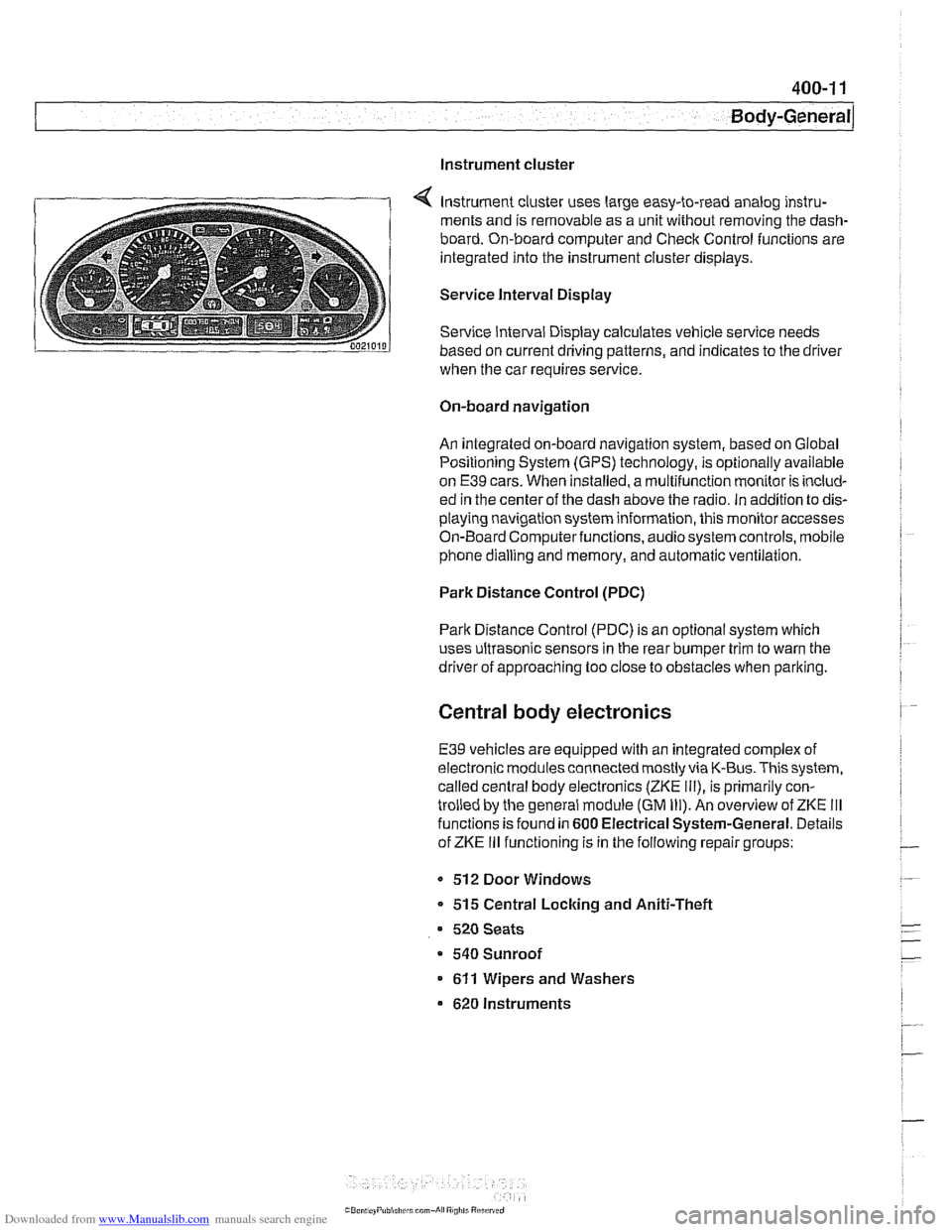
Instrument cluster uses large easy-to-read analog instru-
ments and is removable as a unit without removing the dash-
board. On-board computer and Check Control functions are
integrated into the instrument cluster displays.
Service Interval Display
Service Interval Display calculates vehicle service needs
based on current driving patterns, and indicates to the driver
when the car requires
service
On-board navigation
An integrated on-board navigation system, based on Global
Positioning System (GPS) technology, is optionally available
on
E39 cars. When installed, a multifunction monitor is includ-
ed in the center of the dash above the radio. in addition to dis-
playing navigation system information, this monitor accesses
On-Board Computerfunctions, audiosystem controls, mobile
phone dialling and memory, and automatic ventilation.
Park Distance Control (PDC)
Park Distance Control (PDC) is an optional system which
uses ultrasonic sensors in the rear bumper trim to warn the
driver of approaching too close to obstacles when parlting.
Central body electronics
E39 vehicles are equipped with an integrated complex of
electronic modules connected mostly via K-Bus. This system,
called central body electronics (ZKE
Ill), is primarily con-
trolled by the general module (GM
Ill). An overview of ZKE Ill
functions is found in 600 Electrical System-General. Details
of ZKE
Ill functioning is in the following repair groups:
- 512 Door Windows
* 515 Central Locking and Aniti-Theft
520 Seats
a 540 Sunroof
611 Wipers and Washers
620 Instruments
Page 820 of 1002
Downloaded from www.Manualslib.com manuals search engine
Doors
This repair group covers front and rear door repair informa-
tion. It includes removal and installation of front and rear
doors and trim panels.
For information on
airbag removal and installation, see 721
airbag.
For information on the power door windows and door glass
replacement, see
512 Door Windows.
For information on the power door
loclting system, see 515
Central Locking and Anti-Theft.
WARNING-
E39 cars are fitted with side-impact airbags in the front doors
and optional side impact
airbags in the rear doors. When
servicing doors, always disconnect the negative
(-) battery
terminal. See
721 Airbag System (SRS) for cautions and
procedures
relatinq to the airbaq system.
Front or rear door, removing and installing
- Disconnect negative (-) battery cable.
Prior to disconnecting the battery, read the battery discon-
nection cautionsgiven in
001 General Cautions and warn-
ings.
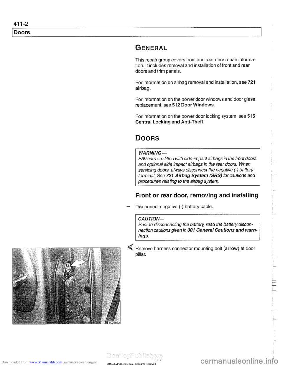
Remove harness connector mounting bolt (arrow) at door
pillar.
Page 822 of 1002
Downloaded from www.Manualslib.com manuals search engine
Doors
~obr adjustment
Front fender to
4.25 mm i 0.25 mm (0.17 i- 0.01 in)
front door gap
Front
door to 4.5 mm i 0.25 mm (0.18 i 0.01 in)
rear door gap
Rear door to rear fender 4.0 mm i 0.25 mm (0.16 i 0.01 in)
Permissible deviation 1 .O mm (0.04 in)
from
~arallel
Tightening torque
Door hinge to door frame
20 Nm (15 it-lb)
Door check, replacing
WARNING -
E39 cars are fitted with side-impact airbags in the front doors
and optional side impact
airbags in the rear doors. When
servicing doors, always disconnect the negative
(-) battery
terminal. See
721 Airbag System (SRS) for cautions and
procedures relating to the
airbag system.
- Close door window completely.
- Disconnect negative (-) battery cable.
CAUTION-
Prior to disconnecting the batter)! read the battery discon-
nection cautions given in
001 General Cautions and
Warnings.
- Remove interior door panel. See Door trim panels, remov-
ing and installing.
- Where applicable, remove side-impact airbag from door. See
721 Airbag System (SRS). Remove door vapor barrier.
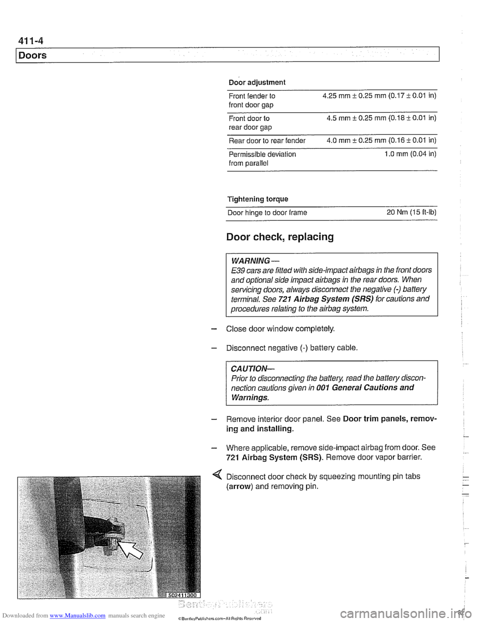
Disconnect door
check by
(arrow) and removing pin. squeezing I mounting
pin tabs