ECO BMW 530i 1998 E39 Workshop Manual
[x] Cancel search | Manufacturer: BMW, Model Year: 1998, Model line: 530i, Model: BMW 530i 1998 E39Pages: 1002
Page 431 of 1002
Downloaded from www.Manualslib.com manuals search engine
. -
Fuel Injection I
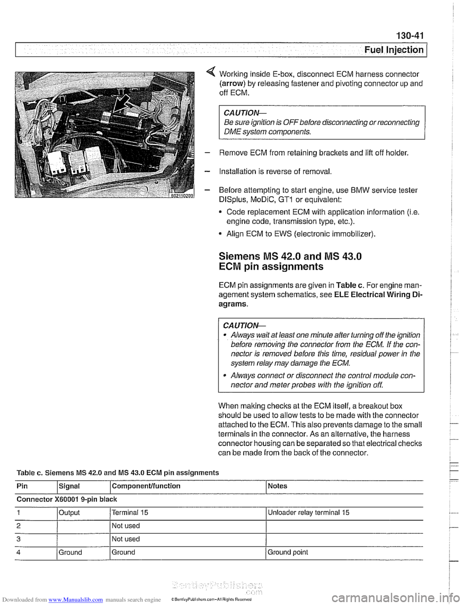
Working inside E-box, disconnect ECM harness connector
(arrow) by releasing fastener and pivoting connector up and
off ECM.
CA UTIOW
Be sure ignition is OFF before disconnecting or reconnecting
DME system components.
Remove ECM from retaining brackets and lift off holder.
Installation is reverse of removal
Before attempting to start engine, use
BMW service tester
DISplus, MoDiC, GTl or equivalent:
* Code replacement ECM with application information (i.e
engine code, transmission type, etc.).
Align ECM to EWS (electronic immobilizer).
Siemens MS 42.0 and MS 43.0
ECM pin assignments
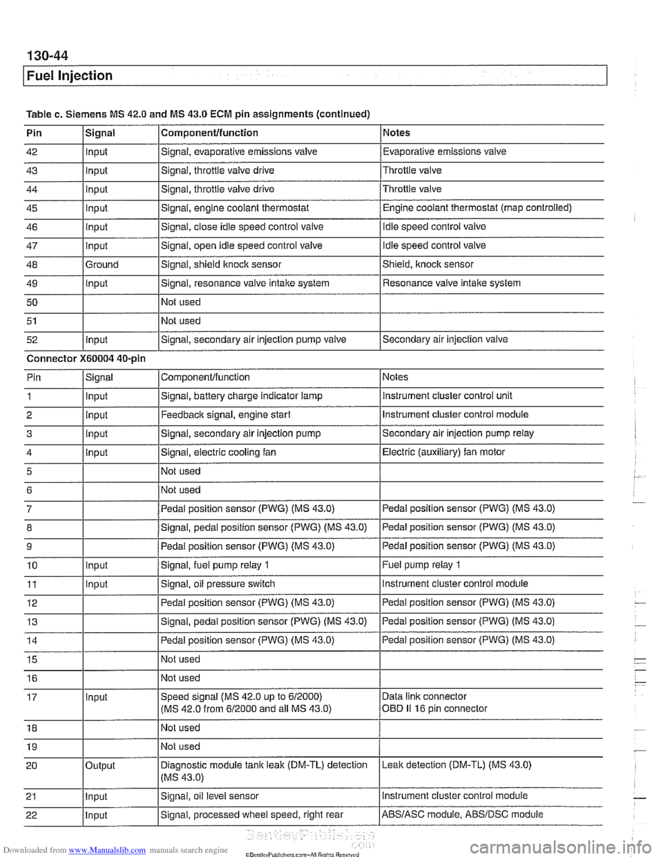
ECM pin assignments are given in Table c. For engine man-
agement system schematics, see
ELE Electrical Wiring Di-
agrams.
/ CAUTIOW I
Al~ays wait at least one mfnule after turning off the ignition
before
remov;ng [he connecror irom rhe ECM. If the con-
nector is removed before this time, residual power
in the
system relay may damage the
ECM.
Always connect or disconnect the control module con-
nector and meter probes with the ignition off.
When making checks at the ECM itself, a
breakout box
should be used to allow tests to be made with the connector
attached to the ECM. This also prevents damage to the small
terminals in the connector. As an alternative, the harness
connector housing can be separated so that electrical checks
can be made from the back of the connector.
Table
c. Siemens MS 42.0 and MS 43.0 ECM pin assignments
Pin
lslgnal l~om~onentlfunction 1 Notes
Connector
X60001 9-pin black
1 loutput I~erminai 15 I Unloeder relay terminal 15
2 I 1 Not used I
3 Not used
4 Ground
Ground Ground
point
Page 434 of 1002
Downloaded from www.Manualslib.com manuals search engine
Fuel Injection
Table c. Siemens MS 42.0 and MS 43.0 ECM pin assignments (continued)
Pin
42
43
44
45
46
47
48
49 50
51
52 Componentlfunction
Signal, evaporative emissions valve
Signal, throttle
valve drive
Signal, throttle valve drive
Signal, engine coolant thermostat
Signal, close idle speed control valve
Signal, open idle speed control valve
Signal, shield
ltnock sensor
Signal, resonance valve
intake system
Not used
Not used
Signal, secondary air injection pump valve
Signal
Input
Input
Input
Input
input
Input
Ground
Input
Input
Notes
Evaporative emissions valve
Throttle valve
Throttle valve Engine coolant thermostat (map controlled)
idle speed control valve
Idle speed control valve
Shield,
knock sensor
Resonance valve intake system
Secondary air injection valve
Connector
X60004 40-pin Notes
instrument cluster control unit
Instrument cluster control module
Secondary air injection pump relay
Electric (auxiliary) fan motor
Pedal position sensor (PWG) (MS 43.0)
Pedal position sensor (PWG) (MS 43.0)
Pedal position sensor (PWG) (MS 43.0)
Fuel pump relay
1
Instrument cluster control module
ComponenVfunction
Signal, battery charge indicator lamp
Feedback signal, engine start
Signal, secondary air injection pump
Signal, electric cooling fan
Not used
Not used
Pedal position sensor (PWG) (MS 43.0)
Signal, pedal position sensor (PWG) (MS 43.0)
Pedal position sensor (PWG) (MS 43.0)
Signal,
fuel pump relay 1
Signal, oil pressure switch
Pin
1
2 3
4
5
6
7
8
9
10
11 Signal
Input
Input
input
input
Input
Input
Page 437 of 1002
Downloaded from www.Manualslib.com manuals search engine
Fuel Injection
M5.2 system features
The Bosch M5.2 system used on 1997 540i models uses an
88-pin control unit. The
M5.2 system has the following func-
tions and capabilities:
Fully sequential cylinder-individual fuel injection.
Integrated adaptive knock control.
Oxygen sensor fuel mixture control.
0 Self-diagnosis and emergency operation characteristics.
CAN-Bus link.
0 OED II functions (misfire detection, catalytic converter
monitoring, oxygen sensor monitor, and fuel tank ventila-
tion system).
Electronic vehicle immobilization via EWS.
One-touch starter function.
Control of characteristic map thermostat.
M5.2.1 system features
The Bosch M5.2.1 system is used on 1998 540i models. The
M5.2.1 control module utilizes the SKE (standard shell con-
struction housing) with 5 connectors and a combined total of
134 pins.
The M5.2.1 systefn has
tile following functions or capabilities:
Separate power supply relay for ignition coils. Leak diagnosis pump (LDP) control and feedback
rnonitor-
ing for evaporative system leak testing.
Fuel evaporative system providing ORVR (on-board refuel-
ing vapor recovery) compliancy.
Batterylalternator charge logic (idle speed varied with the
battery state of charge).
CAN-Bus communications with the instrument cluster
EWS
Ill "rolling code" ISN interface.
More sensitive ignition
knock sensors.
Pulse width modulated (P-W-M) Heating and
AIC (IHKA)
status signal.
Running loss (312-way) solenoid valve.
Page 445 of 1002
Downloaded from www.Manualslib.com manuals search engine
Fuel Injection
- If voltage is present as described above, check wiring be-
tween ECM and valve. If no wiring faults are found, check
ECM signal to valve.
- When replacing idle speed control valve, clean and inspect
all sealing areas.
. Inspect sealing ring in throttle body and replace if neces-
sary.
Throttle position sensor (TPS),
testing and replacing
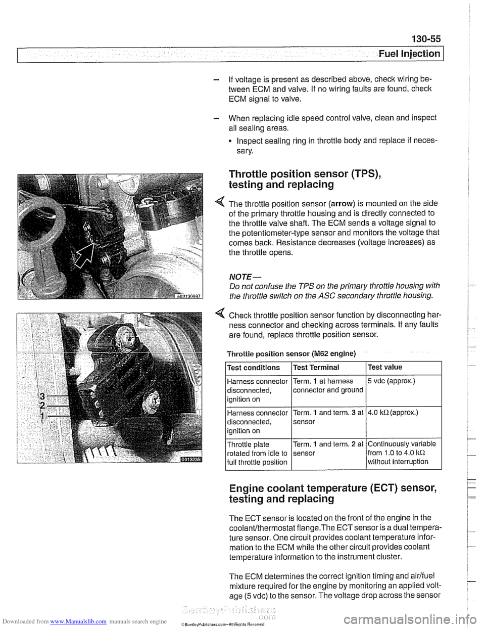
The throttle position sensor (arrow) is mounted on the side
of the primary throttle housing and is directly connected to
the throttle valve shaft. The ECM sends a voltage signal to
the potentiometer-type sensor and monitors the voltage that
comes back. Resistance decreases (voltage increases) as
the throttle opens.
NOTE-
Do not confuse the TPS on the primary throttle housing with
the throttle switch on the
ASC secondary throttle housing.
4 Check throttle position sensor function by disconnecting har-
ness connector and checking across terminals. If any faults
are found, replace throttle position sensor.
Engine coolant temperature (ECT) sensor,
testing and replacing
Throttle position sensor (M62 engine)
The ECT sensor is located on the front of the engine in the
coolanVthermostat flange.The ECTsensor is a dual tempera-
ture sensor. One circuit provides coolant temperature infor-
mation to the ECM while the other circuit provides coolant
temperature information to the instrument cluster.
The ECM determines the correct ignition timing and
airlfuel
mixture required for the engine by monitoring an applied volt-
age
(5 vdc) to the sensor. The voltage drop across the sensor
Test
value
5 vdc (approx.)
4.0 kR(approx.)
Continuously variable
from
1.0 to 4.0 kR
without interruption
Test
conditions
Harness connector
disconnected, ignition on
Harness connector
disconnected,
ignition on
Throttle plate rotated from idle to
full throttle position Test Terminal
Term.
1 at
harness
connector and ground
Term.
1 and term. 3 at
sensor
Term.
1 and term. 2 at
sensor
Page 453 of 1002
Downloaded from www.Manualslib.com manuals search engine
Fuel lnjection
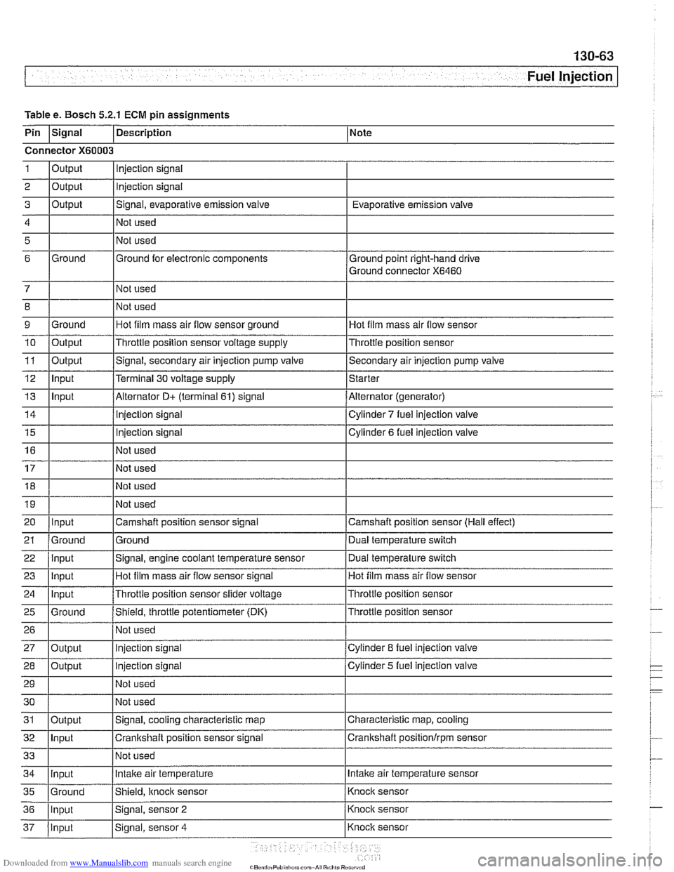
Table e. Bosch 5.2.1 ECM pin assignments
Pin
Isignal 1 Description 1 Note
Connector
X60003
1
2
3
4
5
6
7 8
9 10
11
12
13
14
15
16
17
18
19
20
21
ate alr empe
Output
Output
Output
Ground
Ground
Output
Output Input
Input
Input
Ground
22
23
24
25
26
27
28
29
30
Injection signal
Injection signal
Signal, evaporative emission valve
Not used
Not used
Ground for electronic components
Not used
Not used
Hot film mass air flow sensor ground
Throttle position sensor voltage supply
Signal, engine coolant temperature sensor
Hot
film mass air flow sensor signal
Throttle position sensor slider voltage
Shield, throttle potentiometer (DK) Not used
Injection signal
Injection signal
Not used
Not used
Input
Input
Input
Ground
Output
Output Evaporative emission
valve
Ground point right-hand drive
Ground connector
X6460
Hot film mass air flow sensor
Throttle position sensor
Signal, secondary air injection pump valve
Terminal
30 voltage supply
Alternator
D+ (terminal 61) signal
injection signal
Injection
signal
Not used
Not used
Not used
Not used
Camshaft position sensor signal
Ground Dual temperature switch
Hot film mass air flow sensor
Throttle position sensor
Throttle position sensor
Cylinder
8 fuel injection valve
Cylinder
5 fuel injection valve
Secondary air injection pump
valve
Starter
Alternator (generator)
Cylinder
7 fuel injection valve
Cylinder 6 fuel injection valve
Camshaft position sensor (Hall effect) Dual temperature
switch
Page 457 of 1002
Downloaded from www.Manualslib.com manuals search engine
130-67
Fuel Injection /
ME 7.2 system overview
The Bosch ME 7.2 system is used on 1999 - 2002 540i mod-
els.
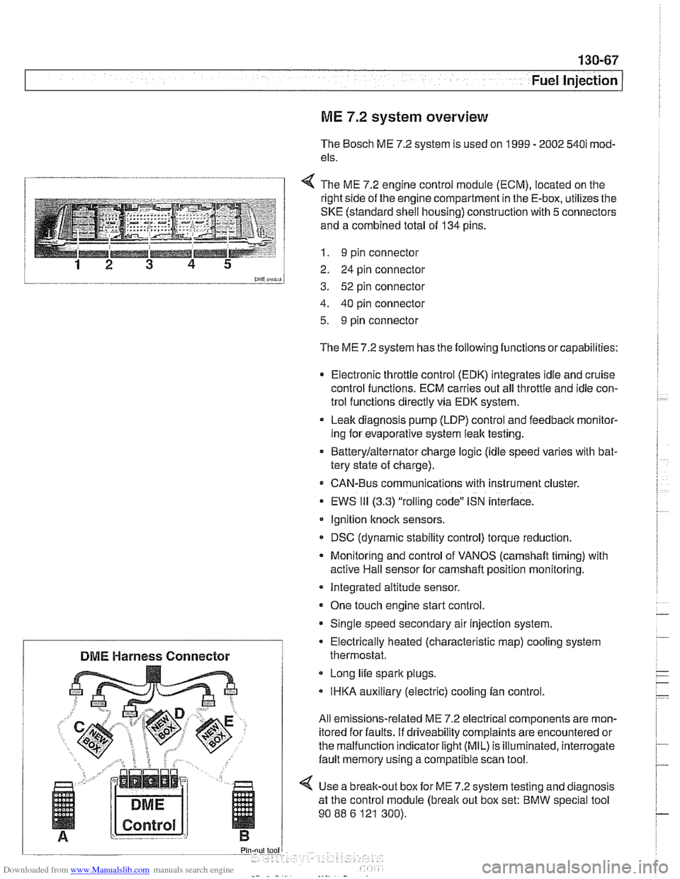
1 4 The ME 7.2 enaine control module (ECM). located on the
l and a combined total of 134 pins.
--__-- 1 I. 9 pin connector
12 3 4 5 2 24 pin connector
0lliC;nii, 3. 52 pin connector
4. 40 pin connector
5. 9 pin connector
The ME 7.2 system has the following functions or capabilities:
Electronic throttle control (EDK) integrates idle and cruise
control functions. ECM carries out all throttle and idle con-
trol functions directly via EDK system.
Leak diagnosis pump
(LDP) control and feedback monitor-
ing for evaporative system leak testing.
Batterylalternator charge logic (idle speed varies with bat-
tery state of charge).
CAN-Bus communications with instrument cluster.
EWS
111 (3.3) "rolling code" ISN interface.
Ignition
knock sensors.
DSC (dynamic stability control) torque reduction.
Monitoring and control of VANOS
(camshaft timing) with
active Hail sensor for camshaft position monitoring.
Integrated altitude sensor.
One touch engine start control
Single speed secondary air injection system.
Long life spark plugs.
IHKA auxiliary (electric) cooling fan control.
All emissions-related ME 7.2 electrical components are mon-
itored for faults. if driveability complaints are encountered or
the malfunction indicator
light (MIL) is illuminated, interrogate
fault memory using a compatible scan tool.
4 Use a break-out box for ME 7.2 system testing and diagnosis
at the control module
(break out box set: BMW special tool
90
88 6 121 300).
Electrically heated (characteristic
map) cooling system
DME Harness Connector thermostat.
Page 459 of 1002
Downloaded from www.Manualslib.com manuals search engine
--
Fuel Injection I
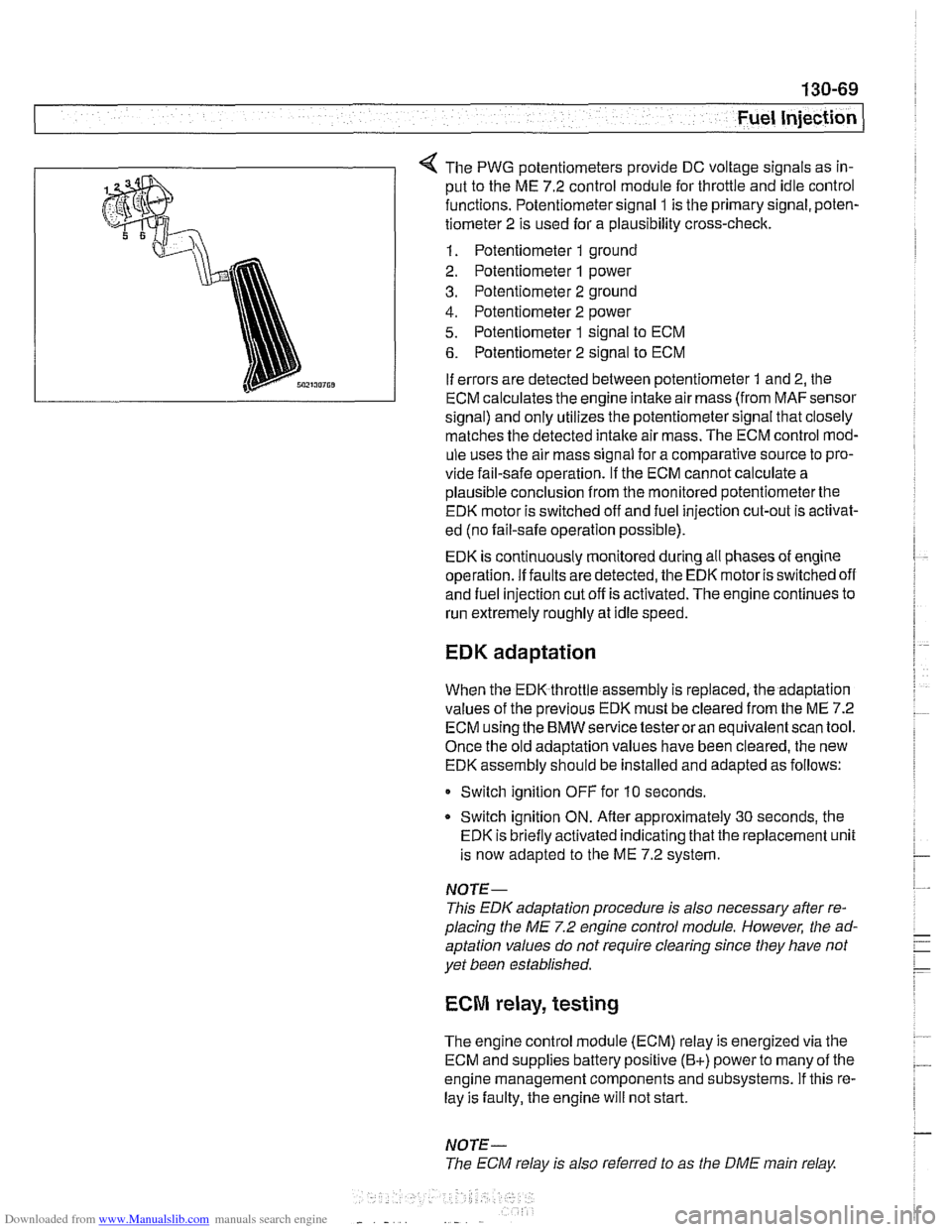
The PWG potentiometers provide DC voltage signals as in-
put to the ME 7.2 control module for throttle and idle control
functions. Potentiometer signal
1 is the primary signal, poten-
tiometer 2 is used for a plausibility cross-check.
1. Potentiometer 1 ground
2. Potentiometer
1 power
3. Potentiometer 2 ground
4. Potentiometer 2 power
5. Potentiometer 1 signal to ECM
6. Potentiometer 2 signal to ECM
If errors are detected between potentiometer
1 and 2, the
ECM calculates the engine intake air mass (from
MAFsensor
signal) and only utilizes the potentiometer signal that closely
matches the detected
intake air mass. The ECM control mod-
ule uses the air mass signal for a comparative source to pro-
vide fail-safe operation.
If the ECM cannot calculate a
plausible conclusion from the monitored potentiometerthe
EDK motor is switched off and fuel injection cut-out is activat-
ed (no fail-safe operation possible).
EDK is continuously monitored during all phases of engine
operation. If faults are detected, the EDK motor is switched off
and fuel injection cut off is activated. The engine continues to
run extremely roughly at idle speed.
EDK adaptation
When the EDK throttle assembly is replaced, the adaptation
values of the previous EDK must be cleared from the ME 7.2
ECM using the BMW service testeroran equivalentscan tool.
Once the old adaptation values have been cleared, the new
EDK assembly should be installed and adapted as follows:
0 Switch ignition OFF for 10 seconds.
* Switch ignition ON. Afler approximately 30 seconds, the
EDK is briefly activated indicating that the replacement unit
is now adapted to the ME 7.2 system.
NOTE-
This EDK adaptation procedure is also necessary after re-
placing the
ME 7.2 engine control module. However, the ad-
aptation values do not require clearing since they have not
yet been established.
ECM relay, testing
The engine control module (ECM) relay is energized via the
ECM and supplies battery positive
(B+) power to many of the
engine management components and subsystems. If this re-
lay is faulty, the engine will not start.
NOTE-
The ECM relay is also referred to as the DME main relay
Page 465 of 1002
Downloaded from www.Manualslib.com manuals search engine
130-75
Fuel Injection
Secondary air injection, overview
The secondary air system pumps ambient air into the exhaust
stream afteracoid engine start to reduce the warm-up time of
the catalytic converters and to reduces HC and CO emis-
sions. The ME
7.2 ECM controls and monitors the secondary
air injection system. The secondary air pump operates at a
starttemperature of between 10°C
(50°F) and 40°C (104°F).
and continues to operate for a maximum of
2 minutes at idle
speed.
The electric air pump draws in ambient air and supplies it to
the
checlc valve. The vacuum vent valve (solenoid) switches
vacuum to open the
checlc valve when activated by the ECM.
Once opened, the checlc
valve allows air to be pumped into
the exhaust stream.
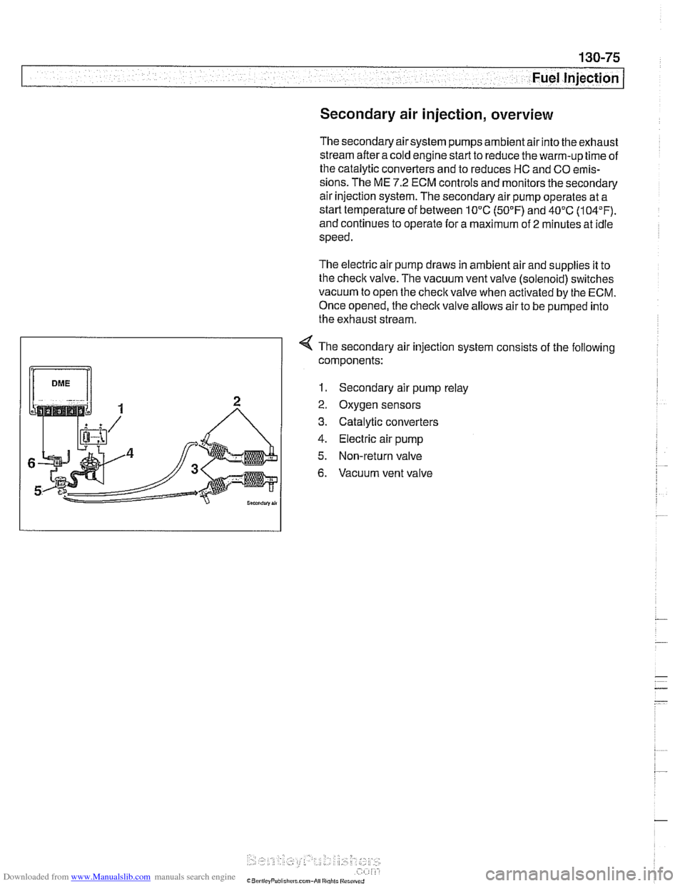
4 The secondary air injection system consists of the following
components:
1. Secondary air pump relay
2. Oxygen sensors
3. Catalytic converters
4. Electric air pump
5. Non-return valve
6. Vacuum vent valve
Page 468 of 1002
Downloaded from www.Manualslib.com manuals search engine
I Fuel Injection
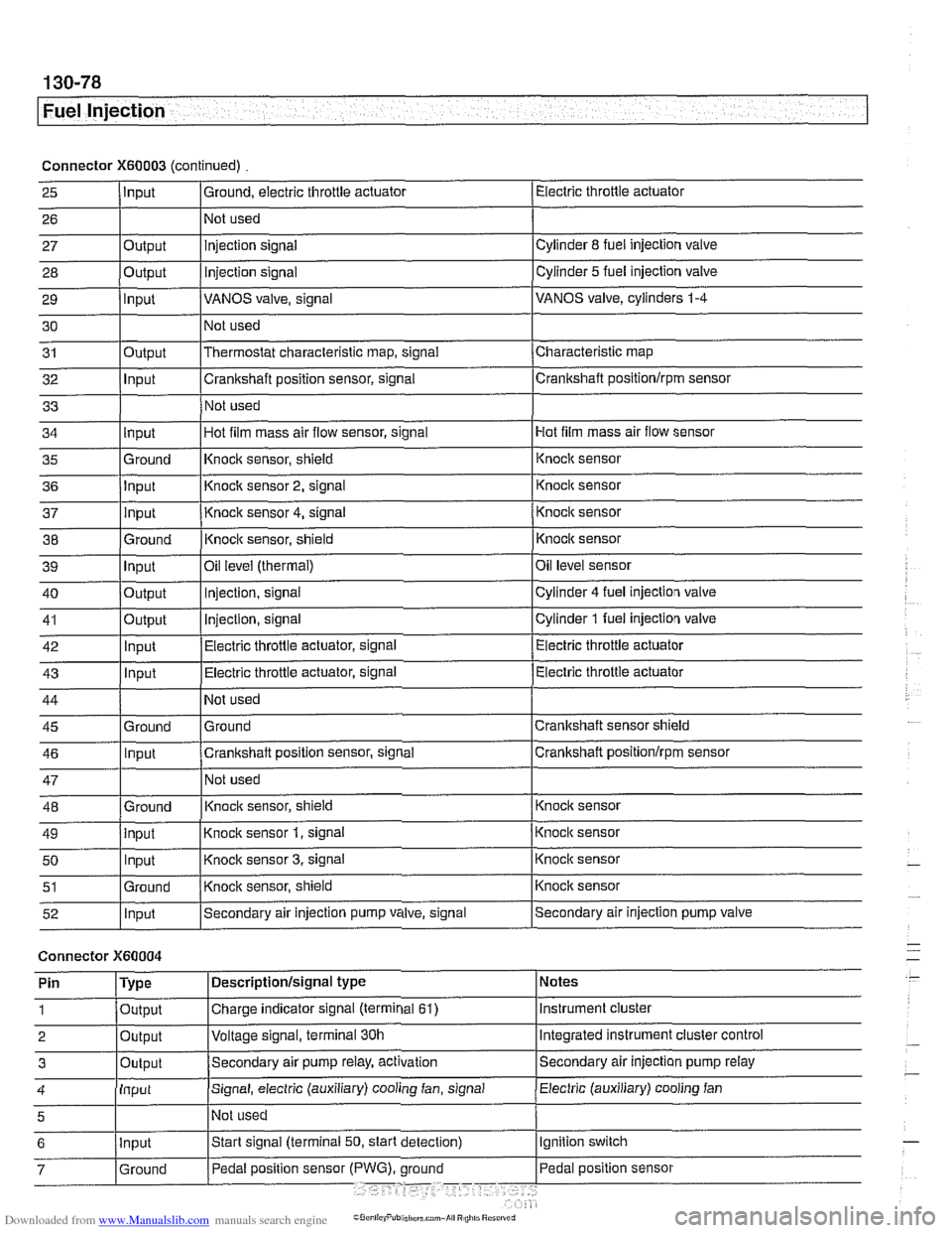
Connector X60003 (continued) Electric throttle actuator
25
- 27 28
29
30
31
32
33
I I I
36 jlnput I Knoclc sensor 2, signal 1 Knock sensor
I I I
Input
26
Output
Output
input
Output
Input
I ' I . I
43 1 ln~ut I Electric throttle actuator, signal (Electric throttle actuator
Ground, electric throttle actuator
1 Not
used
Hot film mass air flow sensor
34
- 37
38
39
40
41
42
injection signal
Injection
signal
VANOS valve, signal
Not used
Thermostat characteristic map, signal
Crankshaft position sensor, signal
Not used
35 l~round I~nock sensor, shield 1 ~nock sensor
Cylinder
8 fuel injection valve
Cylinder
5 fuel injection valve
VANOS valve, cylinders
1-4
Characteristic map
Crankshaft positionlrpm sensor
input
input
Ground
Input
Output
Output
Innut
Hot film mass air flow sensor, signal
I
44
45 46
47
48
49
50
51
52
Connector )(GO004
Knock sensor 4, signal
Knock sensor, shield
Oil
level (thermal)
Injection, signal
Injection, signal
Electric throttle actuator, signal
Not used
Ground
Crankshaft position sensor, signal
Not used
Knoclc sensor, shield
Knock sensor
1, signal
Knock sensor
3, signal
Knock sensor, shield
Secondary air injection pump valve, signal
'
Ground
Input
Ground
input Input
Ground
Input
I' I ... I . ~
Knock sensor
Knocic sensor
Oil level sensor
Cylinder
4 fuel injection valve
Cylinder
1 fuel injection valve
Electric throttle actuator
Crankshaft sensor shield
Crankshaft
positionlrprn sensor
Knock sensor
Knock sensor
Knock sensor
Knock sensor
Secondary air injection pump valve
Notes
Instrument cluster
Integrated instrument cluster control
Secondary air injection pump
relay
Pin
1
2
3
Electric (auxiliary) cooling fan 4
Type
Output
Output
Outout
Descriptionlsignal type
Charge indicator signal (terminal
61)
Voltage signal, terminal 30h
Secondam air pump relay, activation
Input
5
Signal, electric (auxiliary) cooling fan, signal
I~ot used
Page 473 of 1002
Downloaded from www.Manualslib.com manuals search engine
Fuel Tank and Fuel Pump
Fuel pump
The electric fuel pump is mounted in the fuel tank in tandem
with the right side fuel level sender. The fuel pump delivers
pressurized fuel to the fuel injection system.
A pressure regu-
lator maintains system pressure. The quantity of fuel supplied
exceeds demand, so excess fuel returns to the fuel tank via a
return line. See
130 Fuel Injection for more information.
NOTE-
Fuel pump removal procedures are given under Fuel level
sender (right side) and fuel pump, removing and install-
ing.
Fuel tank evaporative control system
Evaporative control, also referred to as running losses con-
trol, is designed to prevent fuel system evaporative losses
from venting into the atmosphere.
The components of this system allow control and monitoring
of evaporative losses by the on-board diagnostic
(OED II)
software incorporated into the engine control module (ECM).
NOTE-
1997 V-8 models (540i) with Bosch DME M5.2 are not
equipped with an
OBD I1 running losses monitoring system.
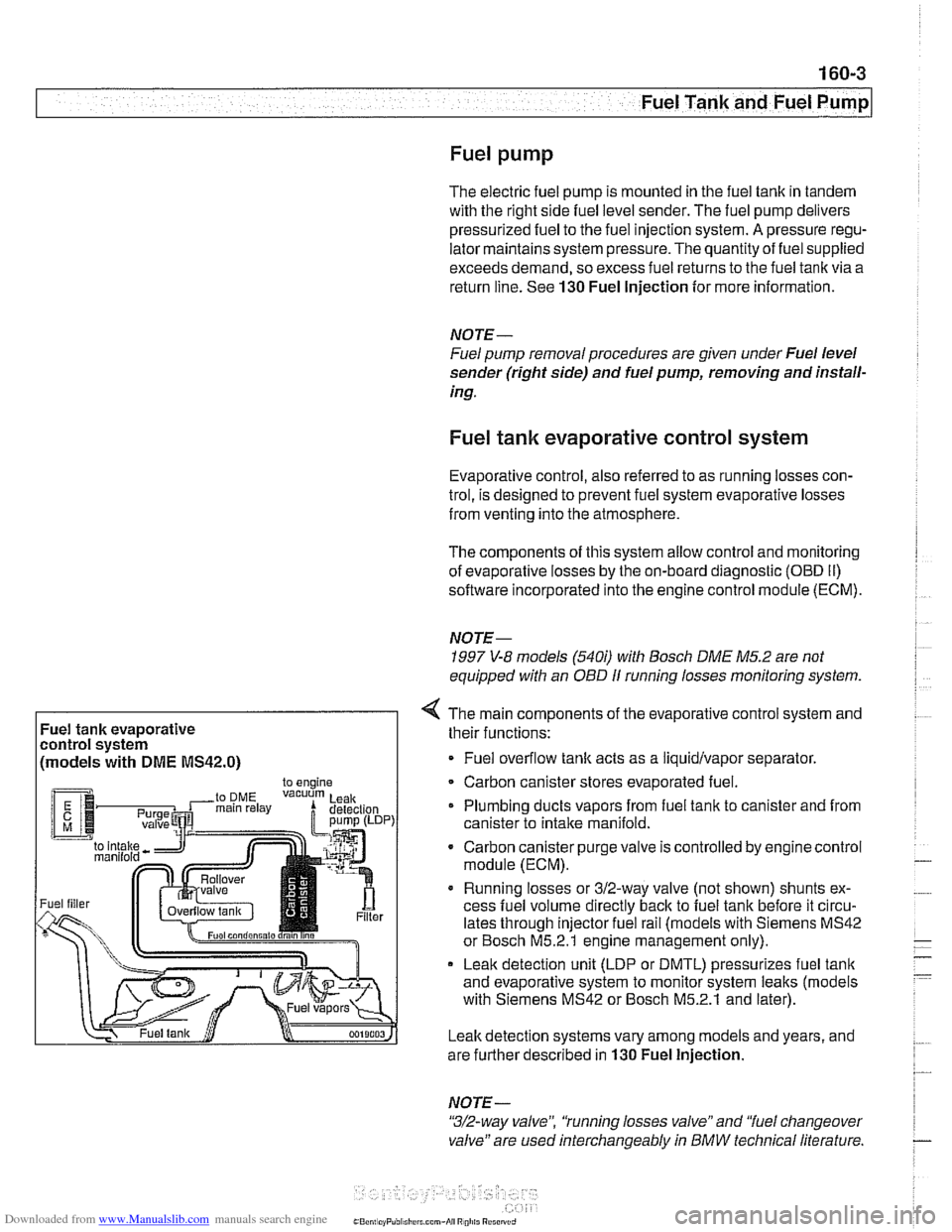
Fuel tank evaporative
control system
(models with
DME MS42.0)
4 The main components of the evaporative control system and
their functions:
Fuel overflow
tank acts as a liquidlvapor separator
Carbon canister stores evaporated fuel.
Plumbing ducts vapors from fuel tank to canister and from
canister to intake
manifold.
- Carbon canister purge valve is controlled by enginecontrol
module (ECM).
Running losses or 312-way valve (not shown) shunts ex-
cess fuel volume directly
back to fuel tank before it circu-
lates through injector fuel rail (models with Siemens MS42
or Bosch M5.2.1 engine management only).
Leak detection unit (LDP or DMTL) pressurizes fuel
tank
and evaporative system to monitor system leaks (models
with Siemens MS42 or Bosch M5.2.1 and later).
Leak detection systems vary among models and years, and
are further described in
130 Fuel Injection.
NOTE -
"3/2-way valve", 'tunning losses valve" and "fuel changeover
valve" are used interchangeably
in BMW technical literature.