roof BMW 530i 1999 E39 User Guide
[x] Cancel search | Manufacturer: BMW, Model Year: 1999, Model line: 530i, Model: BMW 530i 1999 E39Pages: 1002
Page 839 of 1002
Downloaded from www.Manualslib.com manuals search engine
Trunk Lid, Tailgate
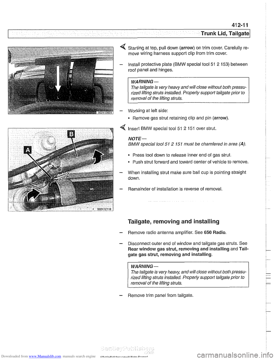
Starting at top, pull down (arrow) on trim cover. Carefully re-
move wiring harness support clip from trim cover.
Install protective plate
(BMW special tool 51 2 153) between
roof panel and hinges.
WARNING -
The tailgate is very heavy and will close without both pressu-
rized lifting
struts installed. Properly support tailgate prior to
removal of the lifting struts.
Worlting at left side:
Remove gas strut retaining clip and pin (arrow).
4 Insert BMW special tool 51 2 151 over strut.
NOTE-
BMW special tool 51 2 151 must be chamfered in area (A).
Press tool down to release inner end of gas strut.
Push strut forward and toward center of vehicle to remove.
- When installing strut make sure ball cup is pointing straight
down.
- Remainder of installation is reverse of removal.
Tailgate, removing and installing
- Remove radio antenna amplifier. See 650 Radio.
- Disconnect outer end of window and tailgate gas struts. See
Rear window gas strut, removing and installing and Tail-
gate gas strut, removing and installing.
WARNING-
The tailgate is very heaq and will close without both pressu-
rized lifling struts installed. Properly support tailgate prior to
removal of the lifling struts.
- Remove trim panel from tailgate.
Page 841 of 1002
Downloaded from www.Manualslib.com manuals search engine
Trunk Lid, Tailgate
Rear window and tailgate, alignment
- Alignment procedures involve adjusting tailgate, window, and
spoiler to have equal space between
iefl and right sides and
to be flush with body. Measurement locations and specific di-
mensions are shown.
- If alignment has been disturbed during repair, adjust fit of tail-
gate to body. Then adjust fit of rear window to tailgate.
Clearance of the rear window is adjusted by adding or re-
moving shims between hinge bracket and rear window
(maximum of three shims).
Adjust spoiler gap to body last.
Height of spoiler is set by alignment of the rear tailgate.
Gap of spoiler to body is set by adjusting spoiler attach-
ment fasteners.
- Lateral and vertical alignment of the window and tailgate is
done using hinge bolts. Fine adjustment of the tailgate to the
body is made using rubber stop buffers and latch assembly.
Spoiler gap specification Rear spoiler to roof 4.25
- 5 mm
(0.167 - 0.197 in)
Max. deviation from parallel 0.5
mm (0.019 in)
Tailgate alignment, preliminary work
- Open rear window and tailgate.
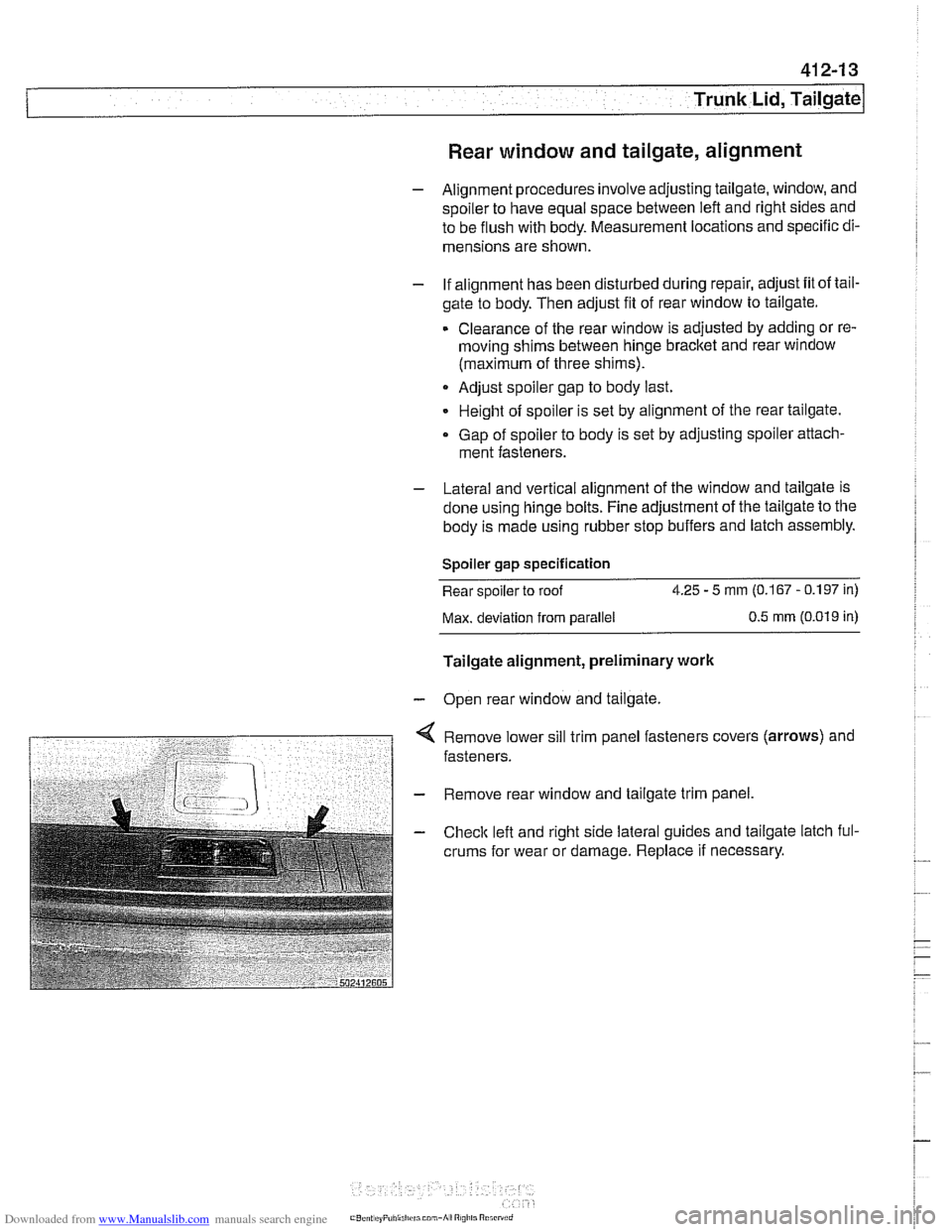
< Remove lower sill trim panel fasteners covers (arrows) and
fasteners.
- Remove rear window and tailgate trim panel.
- Checlc left and right side lateral guides and tailgate latch ful-
crums for wear or damage. Replace
if necessary.
Page 845 of 1002
![BMW 530i 1999 E39 User Guide Downloaded from www.Manualslib.com manuals search engine
. -
Trunk Lid, ~ail~ate]
< Adjustment D:
a = 4.5 rnrn + ll- 0.5 rnrn (0.18 in + 0.041- 0.02 in)
b = 3.7 rnrn +2 l- 1 rnrn (0.1 5 in + 0 BMW 530i 1999 E39 User Guide Downloaded from www.Manualslib.com manuals search engine
. -
Trunk Lid, ~ail~ate]
< Adjustment D:
a = 4.5 rnrn + ll- 0.5 rnrn (0.18 in + 0.041- 0.02 in)
b = 3.7 rnrn +2 l- 1 rnrn (0.1 5 in + 0](/img/1/2822/w960_2822-844.png)
Downloaded from www.Manualslib.com manuals search engine
. -
Trunk Lid, ~ail~ate]
< Adjustment D:
a = 4.5 rnrn + ll- 0.5 rnrn (0.18 in + 0.041- 0.02 in)
b = 3.7 rnrn +2 l- 1 rnrn (0.1 5 in + 0.081 - 0.04 in)
4 Adjustment E:
1 tailgate lid
a=1.3rnrnil rnrn(0.05ini0.04in)
2 rear side panel
b = 4.5 rnrn + 11 - 0.5 rnrn (0.1 8 in + 0.041 - 0.02 in)
4 Adjustment F:
a = 1.3 rnrn 21 rnrn (0.05 in 20.04 in)
b = 1 rnrn 20.5 rnrn (0.04 i0.02 in)
* c=1.3rnrn+lrnrn/-1.3rnrn(0.05in+0.04in-0.05in)
d = 4.5 rnrn + 1 rnrn I - 0.5 rnrn (0.18 in + 0.041 - 0.02 in)
CAUTION-
Rear window frame must not extend above height of roof.
Olherwise, wind noise will be created.
Page 849 of 1002
Downloaded from www.Manualslib.com manuals search engine
41 2-21
Trunk Lid, ~ailaatel
Rear window, adjusting
NOTE- Three versions of rear window are used on
Sport Wagon
models.
Tailgate must be correctly adjusted before rear window ad-
justments are made.
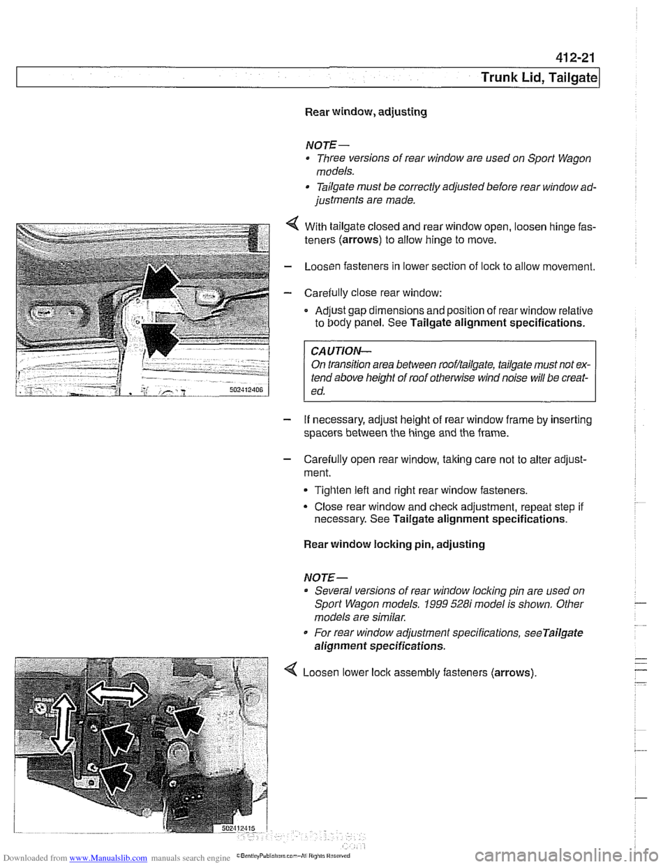
- . . . . . .. .. 4 With tailgate closeo ano rear window open, oosen ninge fas-
teners (arrows) to allow ninge to move.
- LoosL'n fasteners n lower section of ock to al ow movement.
- Care& ly c ose rear window:
Ad.~st gap dmensions and poston of rear window relative
to Oody panel. See Tailgate alignment specifications. .
FA-UTION- I
On transition area between rooflailgate, tailgate must not ex-
tend above height of roof
othe~lise wind noise will be creat-
ed.
- If necessary, adjust height of rear window frame by inserting
spacers between the hinge and the frame.
- Carefully open rear window, taking care not to alter adjust-
ment.
Tighten left and right rear window fasteners.
Close rear window and check adjustment, repeat step if
necessary. See Tailgate alignment specifications.
Rear window locking pin, adjusting
NOTE-- Several versions of rear window
locldng pin are used on
Sport Wagon models.
1999 528i model is shown. Other
models are similar.
For rear window adjustment specifications,
seeTailgate
alignment specifications.
Loosen lower assembly fasteners (arrows)
Page 868 of 1002
Downloaded from www.Manualslib.com manuals search engine
51 2-4
I Door Windows
/ Anti-trap strip
Power window motors
The window motors are mounted on cable regulators. The
window motor control circuit consists of two wires for operat-
ing the motor in both directions.
The motors are activated by relays in the GM
Ill. The relays
provide either power or ground depending on the direction of
window travel. The GM
Ill controls the polarity based on a re-
quest to run the window from a window switch or a conve-
nience
openinglclosing signal.
Convenience openinglclosing
The GM Iii provides the convenience openlclose feature, pro-
viding control of the power windows (and sunroof) from out-
side the vehicle with the key in the driver's door lock. The FZV
(remote key) provides the same function for window opening
only.
Anti-trap protection is active during convenience closing from
the driver's door lock.
If the GM receives a request to operate convenience closing
or opening for more than
110 seconds, the function is deacti-
vated and a
fault code is stored.
Window anti-trap protection
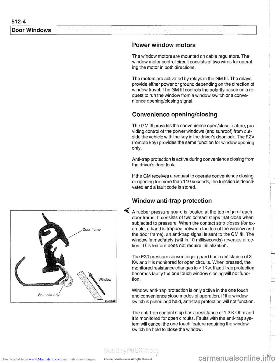
4 A rubber pressure guard is located at the top edge of each
door frame. It consists of two contact strips that close when
subjected to pressure. When the contact strip closes (for ex-
ample, a hand is trapped between the top of the window and
the door frame), an anti-trap signal is sent to the GM
Ill. The
window immediately (within
10 milliseconds) reverses direc-
tion. This feature does not require
initialization.
The E39 pressure sensor finger guard has a resistance of 3
Kw and it is monitored for open circuits. When pressed, the
monitored resistance changes to
< 1 Kw. if anti-trap protection
becomes faulty the one touch window closing will not func-
tion.
Window anti-trap protection is
only active in the one touch
and convenience close modes of operation. If the window
switch is pulled and held, anti-trap protection will not function.
The anti-trap contact strip has a resistance of
1.2 K Ohm and
it is monitored for open circuits. Faults with the anti-trap sys-
tem will cancel the one touch feature requiring the window
switch be held to close the window.
Page 899 of 1002
Downloaded from www.Manualslib.com manuals search engine
Central Locking and Anti-Theft
DWA alarm
The DWA alarm system is
armedldisarmed when thevehicle
is locked / unlocked from either the door or trunk.
Convenience closing
I opening
The windows and sun roof can be closed or opened by hold-
ing the key in the
loclc I unlock position.
Crash sensor
The crash sensor is located in the left front
kick panel. It func-
tions by unlocking all doors in the event of an accident.
NOTE-
Continuous and repeated locliing / unlocking may cause
timedarrest of
the locliing system. When activated, the timed
arrest lasts for two minutes. The timed arrest does not affect
the crash sensor
unlocliing the doors in case of an accident.
Door locks
The driver's door lock location is the only point outside of the
vehicle where the ltey can mechanically control all of the cen-
tral locking system functions.
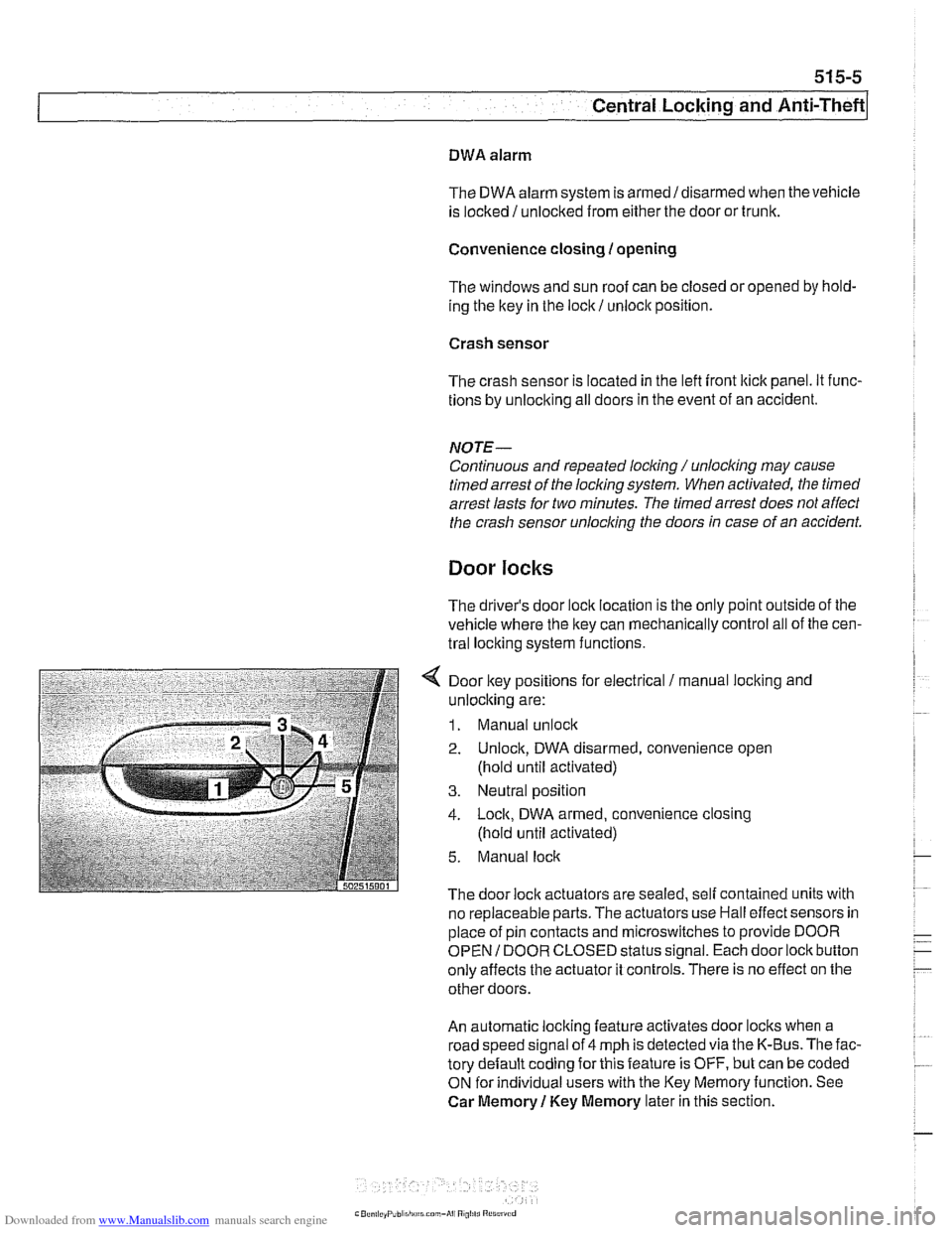
4 Door key positions for electrical / manual loclting and
unlocking are:
1. Manual unlock
2. Unlock, DWA disarmed, convenience open
(hold until activated)
3. Neutral position
4. Lock, DWA armed, convenience closing
(hold until activated)
5. Manual lock
The door lock actuators are sealed. self contained units with
no replaceable parts. The
actuators use Hall effect sensors in
place of pin contacts and microswitches to provide DOOR
OPEN
I DOOR CLOSED status signal. Each door lock button
only affects the actuator it controls. There is no effect on the
other doors.
An automatic locking feature activates door locks when a
road speed signal of 4 mph is detected via the K-Bus. The fac-
tory default coding for this feature is OFF, but can be coded
ON for individual users with the Key Memoryfunction. See
Car Memory
1 Key Memory later in this section.
Page 901 of 1002
Downloaded from www.Manualslib.com manuals search engine
Central Locking and Anti-Theft
Trunk lock
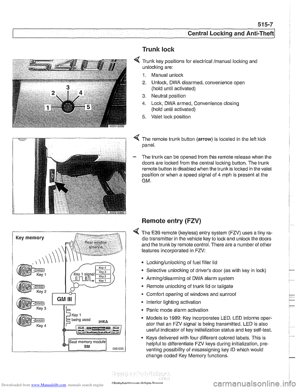
6 Tr~nk ftey pos~rions for eecir'cal mama, locking and
-nlock~ng are:
1. Manual unock .. - - - ........ - ..- .- ................. s.=.=-- 2. Unlock. DWA oisarmed, conven:ence open
(nold
un1:l aclivaledj
3. Ne~tral posit'on
1. -ocn. DWA armeo, Convenience closng
(hold ~nti activated)
5. Valet .oc,t position
. -- .............-... .- . - -.....
Key memory
< The remote trunk button (arrow) is located in the lefl lticlc
panel.
- The trunk can be opened from this remote release when the
doors are locked from the central locking button. The
trunk
remote button is disabled when the trunkis loclted in the valet
position or when a speed signal of
4 mph is present at the
GM.
Remote entry (FZV)
< The €39 remote (keyless) entry system (FZV) uses a tiny ra-
dio transmitter in the vehicle key to
lock and unlock the doors
and the trunk by remote control. There are a number of other
features incorporated in FZV:
Locltinglunloclting of fuel filler lid
Selective unlocking of driver's door (as with key in lock)
Armingldisarming of DWA alarm system
Remote unlocking of
trunk lid or tailgate
Comfort opening of windows and sunroof
* Interior lighting activation
Panic mode alarm activation
* Models to 1999: Key incorporates LED. LED informs oper-
ator that an FZV signal is being transmitted. LED is also
useful indicator of key initialization status and lkey self-test.
Keys delivered with four different colored labels. This is
helpful to differentiate FZV keys during initialization,
pre.
venting possibility of misassigning key ID which would
change coded Key Memory functions.
Page 902 of 1002
Downloaded from www.Manualslib.com manuals search engine
515-8
/Central Locking and Anti-Theft
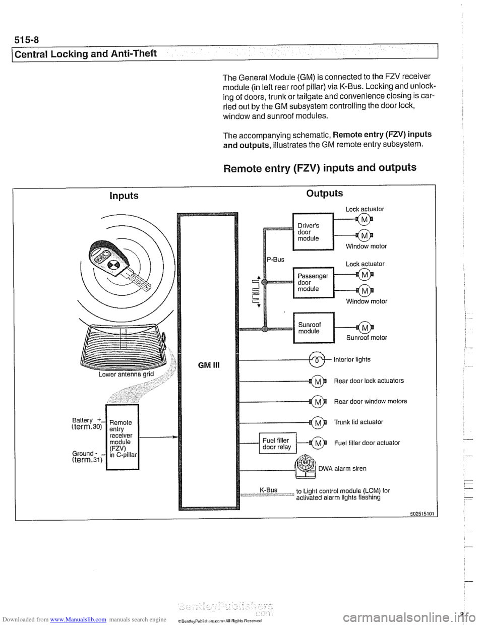
The General Module (GM) is connected to the FZV receiver
module (in left rear roof pillar) via K-Bus. Locking and unlock-
ing of doors, trunk or tailgate and convenience closing is car-
ried out by the GM subsystem controlling the door lock,
window and sunroof modules.
The accompanying schematic, Remote entry
(FZV) inputs
and outputs, illustrates the GM remote entry subsystem.
Remote entry (FZV) inputs and outputs
Inputs Outputs
Page 906 of 1002
Downloaded from www.Manualslib.com manuals search engine
51 5-12
I Central Locking and Anti-Theft
Key battery
9
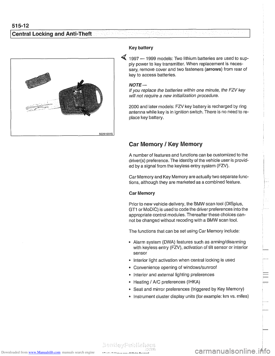
4 1997 - 1999 models: Two lithium batteries are used to sup-
ply power to key transmitter. When replacement is neces-
sary, remove cover and two fasteners (arrows) from rear of
key to access batteries
NOTE-
If you replace the batteries within one minute, the FZV ley
will not require a new initialization procedure.
2000 and later models: FZV key battery is recharged by ring
antenna while ltey is in ignition switch. There is no need to re-
place ltey battery.
Car Memory 1 Key Memory
A number of features and functions can be customized to the
driver(s) preference. The identity of the vehicle user is provid-
ed by a
s~gnal from the keyless entry system (FZV).
Car Memory and Key Memory are actually two separate func-
tions, although they are marketed as a combined feature.
Car Memory
Pr'or ro new
veh c,e de very, the BMW scan roo (DISp us,
GTI or MOD C) is ~sed lo cooc ine driver preierences nro ine
appropriate control modules. Thereafter these choices can-
not be changed without
recoding with a BMW scan tool.
The functions that can be set using Car Memory include:
Alarm system (DWA) features such as armingldisarming
with
lkeyless entry (FZV), activation of tilt sensor or interior
sensor
lnterior light activation when central
locking is used
Convenience opening of
windows/sunroof
lnterior and external lighting preferences
Heating
I A/C preferences (IHKA)
Seat and mirror preferences (triggered by Key Memory)
Instrument cluster display units (for example: km vs. miles)
Page 929 of 1002
Downloaded from www.Manualslib.com manuals search engine
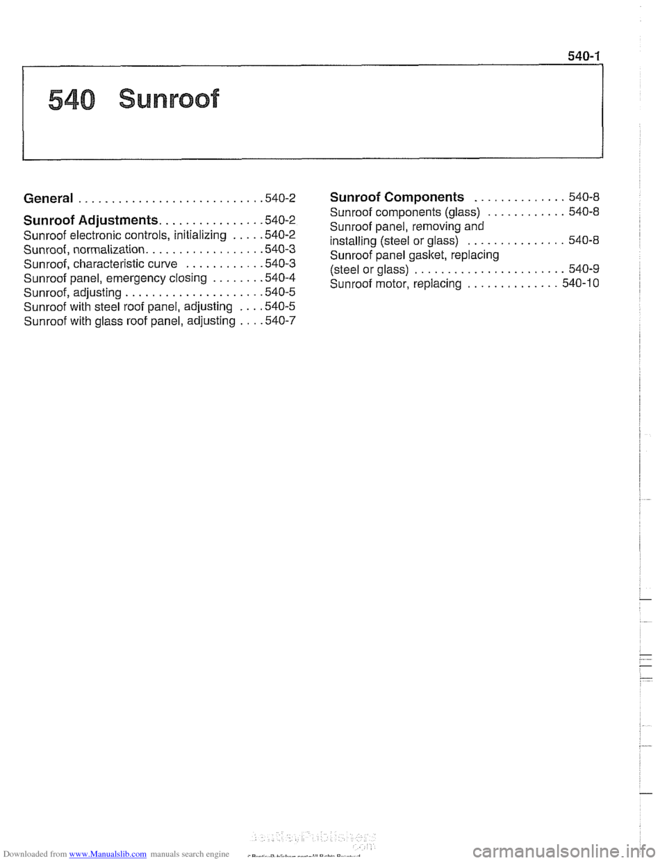
540 Sunroof
General . . . . . . . . . . . . . . . . . . . . . . . . . . . ,540-2
Sunroof Adjustments. . . . . . . . . . . . . . . .540-2
Sunroof electronic controls, initializing . . . . ,540-2
Sunroof, normalization. . . . . . . . . . . . . . . . . ,540-3
Sunroof, characteristic curve . . . . . . . . . . . .540-3
Sunroof panel, emergency closing . . . . . . . ,540-4
Sunroof, adiustino . . . . . . . . . . . . . . . . . . . . ,540-5
~unroofwitil steel roof panel, adjusting . . . ,540-5
Sunroof with glass roof panel, adjusting . . . ,540-7
Sunroof Components . . . . . . . . . . . . . . 540-8
Sunroof components (glass)
. . . . . . . . . . . . 540-8
Sunroof panel, removing and
installing (steel or glass)
. . . . . . . . . . . . . . . 540-8
Sunroof panel gasket, replacing
(steel or glass)
. . . . . . . . . . . . . . . . . . . . . . . 540-9
Sunroof motor, replacing
. . . . . . . . . . . . . . 540-10