catalytic converter BMW 530i 1999 E39 Workshop Manual
[x] Cancel search | Manufacturer: BMW, Model Year: 1999, Model line: 530i, Model: BMW 530i 1999 E39Pages: 1002
Page 33 of 1002
Downloaded from www.Manualslib.com manuals search engine
020 Maintenance
General ........................... .02 0.2
Special tools ........................ .02 0.2
Service Interval Indicator (Sll) ........... .02 0.3
Service Interval Indicator (Sll), resetting ... .02 0.3
Inspection I, Inspection 11 ............... .02 0.5
Maintenance Tables ................ .02 0.6
Fluid and Lubricant Specifications .. .02 0.9
Fluids and lubricants ................. .02 0.10
Engine Oil Service ................ .02 0.1 I
Engine oil. checking level ............. .02 0.12
Engine oil and filter. changing .......... .02 0-13
Engine Compartment Maintenance . .02 0.14
Accelerator and linkage ............... .02 0.14
Air filter. replacing ................... .02 0.1 4
Cooling system service ............... .02 0.15
Engine drive belt service .............. .02 0.16
Idlespeed .......................... 020-19
Catalytic converter and oxygen sensors .. .02 0.19
Power steering fluid, checking level ..... .02 0.20
Spark plugs ........................ .02 0.20
Spark plugs, replacing ................ .02 0.21
Interior ventilation microfilter, replacing ... .02 0.22
Other Mechanical Maintenance ..... .02 0.22
Battery, checking. cleaning. and replacing .02 0-22
Brake fluid. replacing ................. .02 0-24
Brake pad 1 rotor wear. checking ........ .02 0.24
Brake system, inspecting ............. .02 0.25
Parking brake. checking ............... 020-25
Clutch fluid. checking ................. 020-26
Differential oil level. checking ........... 020-26
Drive axle joint (CV joint) boots. inspecting 020-27
Exhaust system. inspecting ............ 020-27
Fuel filter. replacing .................. 020-27
Fuel tank and fuel lines. inspecting ...... 020-28
Suspension. front. inspecting ........... 020-29
Suspension. rear. inspecting ........... 020-29
Tires. checking inflation pressure ........ 020-29
Tires. rotating ....................... 020-29
Transmission service. automatic ........ 020-29
Transmission service. manual .......... 020-30
Transmission fluid. checking and filling
(manual transmission)
................ 020-30
Wheels. aligning ..................... 020-30
Body and Interior Maintenance ..... 020-31
Body and hinges. lubricating ........... 020-31
Exterior washing ..................... 020-31
Interior care ........................ 020-31
Leather upholstery and trim ............ 020-31
Polishing ........................... 020-32
Seat belts .......................... 020-32
Special cleaning ..................... 020-32
Washing chassis ..................... 020-32
Waxing ............................ 020-32
Windshield wiper blade maintenance ..... 020-33
Page 51 of 1002
Downloaded from www.Manualslib.com manuals search engine
Maintenance
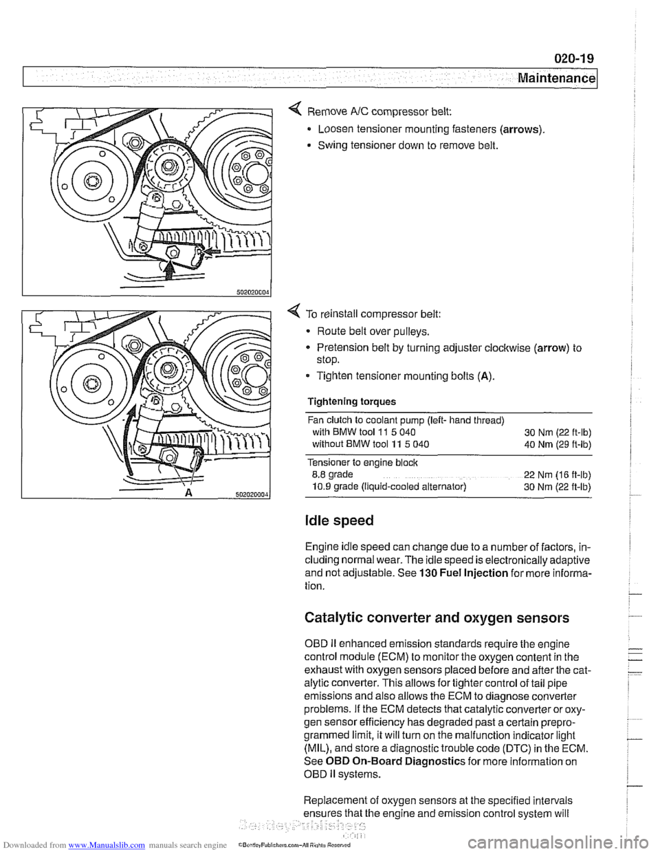
< Remove NC compressor belt:
Loosen tensioner mounting fasteners (arrows)
Swing tensioner down to remove belt.
4 To reinstall compressor belt:
Route belt over pulleys.
* Pretension belt by turning adjuster clockwise (arrow) to
stop.
- Tighten tensioner mounting bolts (A).
Tightening torques
Fan clutch to coolant pump (left- hand thread)
with BMW tool
11 5 040
30 Nm (22 ft-lb)
without BMW tool 11 5 040
40 Nm (29 ft-lb)
Tensioner to engine block
8.8 grade
22 Nm (16 ft-lb)
10.9 grade (Ilquid-cooled alternator) 30 Nm (22 ft-lb)
Idle speed
Engine idle speed can change due to a number of factors, in-
cluding normal wear. The idle speed is electronically adaptive
and not adjustable. See
130 Fuel Injection for more informa-
tion.
Catalytic converter and oxygen sensors
OBD II enhanced emission standards require the engine
control module (ECM) to monitor the oxygen content in the
exhaust with oxygen sensors placed before and after the cat-
alytic converter. This allows for tighter control of tail pipe
emissions and also allows the ECM to diagnose converter
problems. If the ECM detects that catalytic converter or oxy-
gen sensor efficiency has degraded past a certain
prepro-
grammed limit, it will turn on the malfunction indicator light
(MIL), and store a diagnostic trouble code (DTC) in the ECM.
See OBD On-Board Diagnostics for more information on
OBD
ll systems.
Replacement of oxygen sensors at the specified intervals
he engine and emission control system will
Page 354 of 1002
Downloaded from www.Manualslib.com manuals search engine
120-6
lgnition System
lgnition system, troubleshooting
Troubleshooting ignition system faults should begin with an
interrogation of the On-Board Diagnostics (OBD
II) system.
The OBD
II system detects ignition system misfire and other
related faults. When faults are detected, the OBD
II system
stores a Diagnostic Trouble Code (DTC) in the Engine Con-
trol Module (ECM) along with other pertinent fault information.
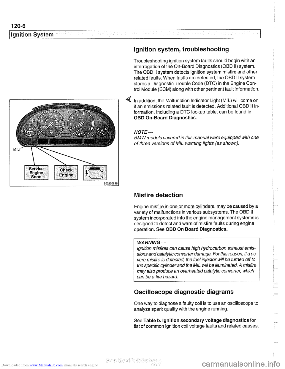
4 In addition, the Malfunction Indicator Light (MIL) will come on
if an emissions related fault is detected. Additional OBD
II in-
formation, including a DTC lookup table, can be found in
OED On-Board Diagnostics.
NOTE-
BMWmodels covered in this manual were equipped with one
of three versions of
MIL warning lights (as shown).
Misfire detection
Engine m~sfire in one or more cylinders, may be caused by a
var~ety of malfunctions in various subsystems. The OBD II
system ~ncorporated into the engine management systems is
des~gned to detect and warn of misfire faults during englne
operat~on. See OED On Board Diagnostics.
WARNING -
lgnition misfires can cause high hydrocarbon exhaust emis-
sions andcatalytic converter damage. For this reason, if a se-
vere misfire is detected, the fuel injector
will be turned off to
the specific cylinder and the
MIL will be illuminated. A misfire
may also produce an overheated catalytic converter, which
can be a fire hazard.
Oscilloscope diagnostic diagrams
One way to diagnose a faulty coil is to use an oscilloscope to
analyze spark quality with the engine running.
See Table b. lgnition secondary voltage diagnostics for
list of common ignition
coil voltage faults and related causes.
Page 395 of 1002
Downloaded from www.Manualslib.com manuals search engine
Fuel Injection
Warnings and cautions
For personal safety, as well as the protection of sensitive
electronic components, adhere to the warnings and cautions
on the following pages.
WARNING-
Gasoline is highly flammable and its vapors are explosive.
Do not smoke or work on a car near heaters or other fire
hazards when diagnosing and repairing fuel system prob-
lems. Have a fire extinguisher available in case of an emer-
gency
Renew fuel system hoses, clamps and O-rings any
time they are removed.
When working on an open fuel system, wear suitable
hand protection, as prolonged contact
with fuel can
cause illnesses and skin disorders.
* The ignition system produces high voltages that can be
fatal. Avoid contact with exposed terminals. Use ex-
treme caution when
working on a car with the ignition
switched on or the engine running.
CAUTION-
- Disconnecting the battery may erase fault code($ storedin
memory Check for fault codes prior to disconnecting the
battery cables. Read the battery disconnection cautions in
001 General Warnings and Cautions.
a Connect and disconnect the DME system wiring and
1 test equipment leads only when the ignition is switched
off.
Wait at least 1 minute after turning off the ignition be-
fore removing the engine control module (ECM) con-
nector. If the connector is removed before this time,
residualpower in the system relay may damage the
control module.
Fuel system cleaners and other chemical additives oth-
er than those specifically recommended by BMW may
damage the catalytic converter, the oxygen sensor or
other fuel supply components.
* Do not connect any test equipment that delivers a 12-
volt power supply to terminal 15 (+) of the ignition coil.
The current flow may damage the ECM. In general,
connect test equipment only as specified by BMW or
the equipment maker.
Only use a digital
multirneter for electrical tests. Only
use an LED test light for
quiclc tests.
Page 407 of 1002
Downloaded from www.Manualslib.com manuals search engine
Fuel Injection 1
NOTE-
The 1998 5281' with MS 41.1 requires a barometric pressure
sensor input signal for activation of the
LDP check. This sen-
sor is located on the passenger side strut tower
fo~lard of
ABS/ASC hydraulic unit.
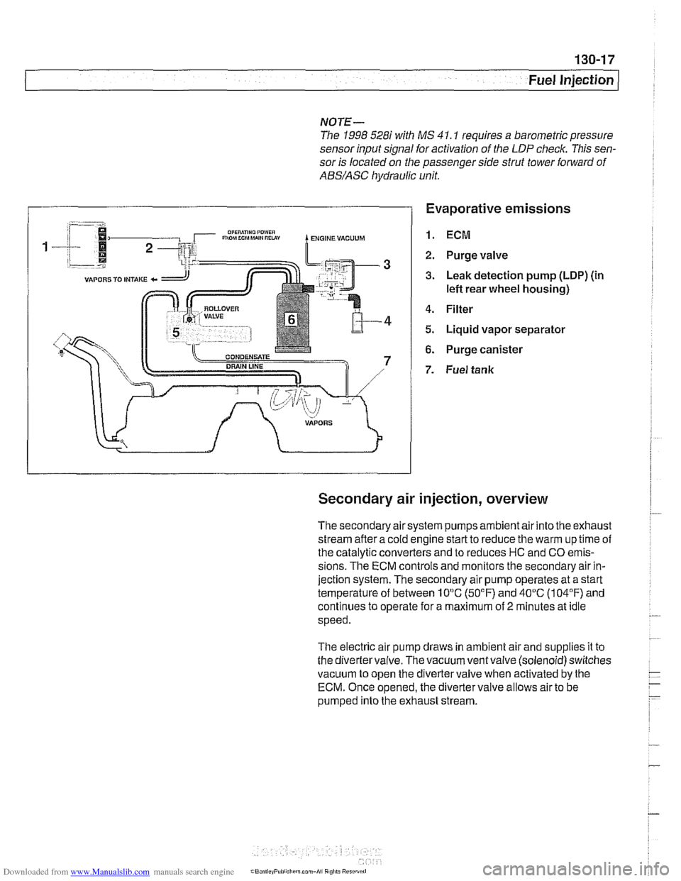
Evaporative emissions
1. ECM
2. Purge valve
3. Leak detection pump (LDP) (in
lefl rear wheel housing)
4. Filter
5. Liquid vapor separator
6. Purge canister
7. Fuel tank
Secondary air injection, overview
The secondary air system pumps ambient air into the exhaust
stream afler a cold engine start to reduce the warm up time of
the catalytic converters and to reduces HC and CO emis-
sions. The ECM controls and monitors the secondary air in-
jection system. The secondary air pump operates at a start
temperature of between 10°C (50°F) and 40°C (104°F) and
continues to operate for a maximum of
2 minutes at idle
speed.
The electric air pump draws in ambient air and supplies it to
the divertervalve. The vacuum ventvalve (solenoid) switches
vacuum to open the divertervalve when activated by the
ECM. Once opened, the diverter valve allows air to be
pumped into the exhaust stream.
Page 410 of 1002
Downloaded from www.Manualslib.com manuals search engine
I Fuel Injection
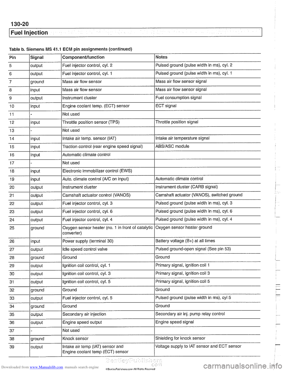
Table b. Siemens MS 41.1 ECM pin assignments (continued)
Pin
l~iqnal I Componentlfunction 1 Notes I - I I
5 loutput I Fuel injector control, cyl. 2 I Pulsed ground (pulse width in ms), cyl. 2 I I I
6 loutput /Fuel injector control, cyi. 1 I Pulsed ground (pulse width in ms), cyl. 1
I I I
14 linput I Intake air temp. sensor (IAT) I Intake air temperature signal
- 7
8
9
10
11
12
13
ground
input
output
input
input
15
16
17 18
19
20
21
22
I - I I
35 loutput /Secondary air injection ISecondary air inj. pump relay control
25
26
27
28
29
30
31
32
33
36
/output I Engine speed output IEngine speed signal
Mass air flow sensor
Mass air flow sensor
instrument cluster
Engine coolant
temp.
(ECT) sensor
Not used
Throttle position sensor (TPS)
Not used
input
input
input
input
output
output
out~ut
37 1 - /Not used I
Mass air flow sensor signal
Mass air flow sensor signal
Fuel consumption signal
ECT signal
Throttle position signal
ground
input
output
ground
output
output
output
ground
output
Traction control (rear engine speed signal) Automatic climate control
Not used Electronic immobilizer control (EWS)
Auto. climate control
(AIC on input)
instrument
cluster
Camshaft actuator control (VANOS)
Fuel iniector control, cvl.
3
AES/ASC module
Automatic climate control instrument cluster (CARE signal)
Camshaft actuator (VANOS), switched ground
Pulsed ground (pulse width in
ms), cyl. 3
Oxygen sensor heater (no. 1 in front of catalytic
converter)
Power supply (terminal
30)
Idle speed control valve
Ground
Ignition coil control, cyl.
1
Ignition coil control, cyl. 3
Ignition coil control, cyl. 5
Ground Fuel injector control, cyl.
5
Oxygen sensor heater ground
Battery voltage
(E+) at all times
Pulsed ground-open signal (See pin
53)
Ground
Primary signal, ignition coil
1
Primary signal, ignition coil 3
Primary signal, ignition coil 5
Ground
Pulsed ground (pulse width in ms), cyl
5
Page 411 of 1002
Downloaded from www.Manualslib.com manuals search engine
Fuel lniection 1
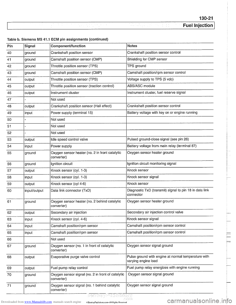
Table b. Siemens MS 41.1 ECM pin assignments (continued)
Pin
lSiqnal 1 Componentlfunction / Notes I - I I
40 1 ground /Crankshaft position sensor /crankshaft position sensor control I - I I
41 1 ground /Camshaft position sensor (CMP) /shielding for CMP sensor I - I I
42 1 ground I~hrottie position sensor (TPS) /TPS ground
43
44
45
46
47
48
49
50
51 ground
output
output
output
outout
I I I
input
52 53
54
55
56 57
58
59
60
61
62
63
64
65
66 Camshaft position sensor (CMP)
Throttle position sensor (TPS)
Throttle position sensor (traction control)
Instrument cluster
Not used
Crankshaft position sensor (Hall effect)
I~ot used
I I I
Fuel pump relay control Camshaft
positionlrpm sensor control
Voltage
supply to TPS (5 vdc)
ABSIASC module
Instrument cluster, fuel reserve signal
Crankshaft position sensor control
Power supply (terminal 15)
Not used
Not used
output input
ground
ground
output
input
output
inputloutput
ground
output
input
input
input
I I
Battery voltage with key on or engine running
Oxygen sensor signal ground
67
Idle speed control valve
Power supply
Oxygen sensor heater (no. 2 in front catalytic
converter)
Ignition circuit
Knock sensor
(cyl. 1-3)
Knock sensor (cyl. 1-3)
Knock sensor
(cyl4-6)
Data linic connector (TxD)
Oxygen sensor heater (no. 2 behind catalytic
converter)
Secondary air injection
Knock sensor (cyl. 4-6)
Camshaft
positionlrpm sensor
Camshaft
positionlrpm sensor
Not used
Pulse ground with engine at normal temperature with
varying engine load
68 Pulsed ground-close signal (see
pin 26)
Battery voltage from main relay (terminal 87)
Oxygen sensor heater ground
Ignition circuit monitoring signal
Knock sensor
Knock sensor signal
Knock sensor
Diagnostic
TxD (transmit) signal to pin 18 in data link
connector
Oxygen sensor heater ground
Secondary air injection control
valve
Knocic sensor signal
Camshaft positionlrpm sensor control
Camshaft
positionlrpm sensor control
ground Oxygen sensor
(no.
1 in front of catalytic
converter)
output Evaporative purge
valve control
Page 437 of 1002
Downloaded from www.Manualslib.com manuals search engine
Fuel Injection
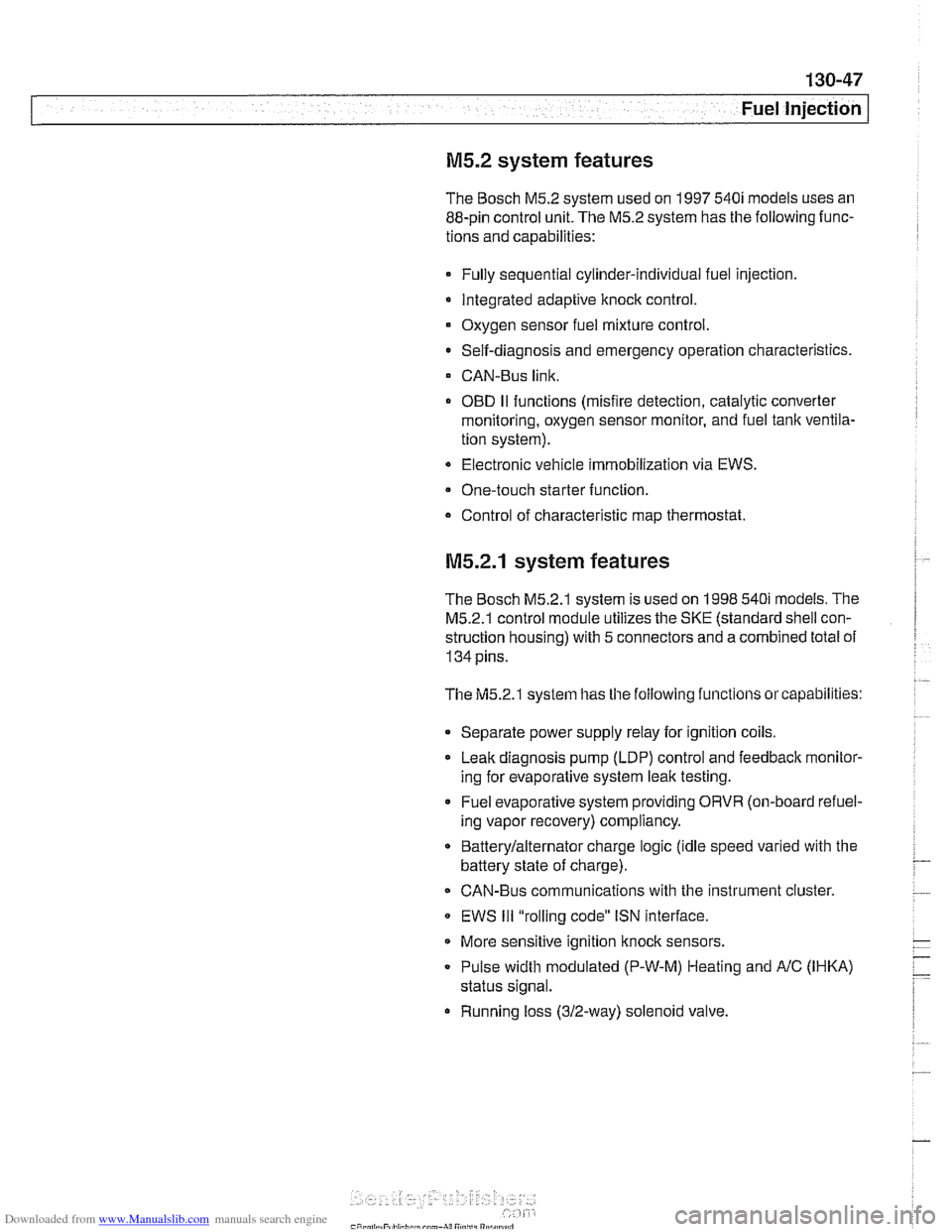
M5.2 system features
The Bosch M5.2 system used on 1997 540i models uses an
88-pin control unit. The
M5.2 system has the following func-
tions and capabilities:
Fully sequential cylinder-individual fuel injection.
Integrated adaptive knock control.
Oxygen sensor fuel mixture control.
0 Self-diagnosis and emergency operation characteristics.
CAN-Bus link.
0 OED II functions (misfire detection, catalytic converter
monitoring, oxygen sensor monitor, and fuel tank ventila-
tion system).
Electronic vehicle immobilization via EWS.
One-touch starter function.
Control of characteristic map thermostat.
M5.2.1 system features
The Bosch M5.2.1 system is used on 1998 540i models. The
M5.2.1 control module utilizes the SKE (standard shell con-
struction housing) with 5 connectors and a combined total of
134 pins.
The M5.2.1 systefn has
tile following functions or capabilities:
Separate power supply relay for ignition coils. Leak diagnosis pump (LDP) control and feedback
rnonitor-
ing for evaporative system leak testing.
Fuel evaporative system providing ORVR (on-board refuel-
ing vapor recovery) compliancy.
Batterylalternator charge logic (idle speed varied with the
battery state of charge).
CAN-Bus communications with the instrument cluster
EWS
Ill "rolling code" ISN interface.
More sensitive ignition
knock sensors.
Pulse width modulated (P-W-M) Heating and
AIC (IHKA)
status signal.
Running loss (312-way) solenoid valve.
Page 441 of 1002
Downloaded from www.Manualslib.com manuals search engine
130-51
Fuel Injection
Oxygen sensors, checking
The oxygen sensor provides an input voltage signal [0.2 vdc
(lean) to 0.8 vdc (rich)] to the
ECM based on the oxygen con-
tent in the exhaust gas. To generate voltage, the sensor tem-
perature must exceed 575"
F (300" C). Therefore the sensor
is electrically heated.
NO JE -
The test given below is not a conclusive test of oxygen sen-
sor efficiency and does not test how the oxygen sensor re-
acts to changing conditions. Pin numbers and wire colors
can vary Always check the wiring diagrams to confirm wire
color and pin assignment.
0 The oxygen sensorconnectorplugs are locatednext to the
catalytic converters.
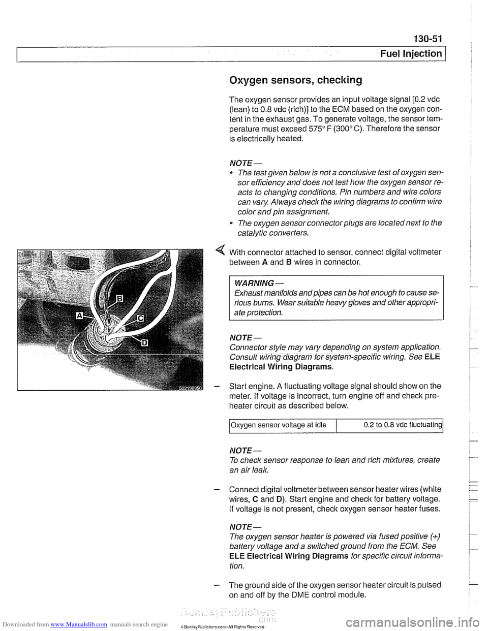
With connector attached to sensor, connect digital voltmeter
between
A and B wires in connector.
WARNING -
Exhaust manifolds andpipes can be hot enough to cause se-
rious burns. Wear suitable heavy gloves and other appropri-
ate protection.
NOJE-
Connector style may vary depending on system application.
Consult wiring diagram for system-specific wiring. See
ELE
Electrical Wiring Diagrams.
Start engine.
A fluctuating voltage signal should show on the
meter.
If voltage is incorrect, turn engine off and check pre-
heater circuit as described below.
NOJE-
To check sensor response to lean and rich mixtures, create
an air leak.
Oxygen sensor
voltage at idle
- Connect digital voltmeterbetween sensor heaterwires (white
wires,
C and D). Start engine and check for battery voltage.
If voltage is not present, check oxygen sensor heater fuses.
0.2 to 0.8 vdc fluctuating
NOJE-
The oxygen sensor heater is powered via fusedpositive (+)
battery voltage and a switchedground from the ECM. See
ELE Electrical Wiring Diagrams for specific circuit informa-
tion.
- The ground side of the oxygen sensor heater circuit is pulsed
on and off by the
DME control module.
Page 450 of 1002
Downloaded from www.Manualslib.com manuals search engine
130-60
/Fuel lniection
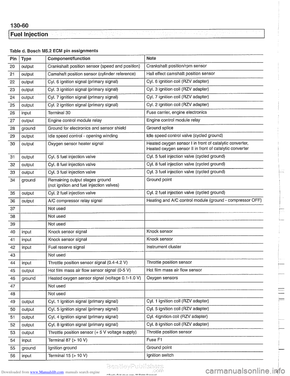
Tabled. Bosch M5.2 ECM pin assignments
Note
Pin
21
20 I output / Crankshaft position sensor (speed and position) I Crankshaft positionlrpm sensor
23
I - I I 29 1 output I Idle speed control - opening winding I Idle speed control valve (cycled ground)
Type
22
1 output I Cvl. 6 ignition signal (primary signal) I Cyl. 6 ignition coil (RZV adapter)
output
25
26
27
28
Component/function
24 1 outout I Cvl. 7 iqnition siqnal (primary signal) I Cyl. 7 ignition coil (RZV adapter)
output
4 outbut I' I - I Cyl. 3
fuel injection valve I Cyl. 3 fuel injection valve (cycled ground)
Camshaft position
sensor (cylinder reference)
output input
output
oround
30
31
32
ground Hall effect camshaft position sensor
Cyl. 3 ignition signal (primary signal)
output
I
Cyl. 3 ignition coil (RZV adapter)
. - . .. . .
Cyl. 2 ignition signal (primary signal)
Terminal 30
Engine control module relay
Ground for electronics and sensor shield
output
output
outout
Remaining output stages ground
(not iclnition and fuel iniection valves) Cyl.
2 ignition coil (RZV adapter)
Fuse carrier, engine electronics
Engine control module relay
Ground splice ,
Cyl. 2 fuel injection valve
Oxygen sensor heater signal
Cyl. 5
fuel injection valve
Cvl. 8 fuel iniection valve
AIC comuressor relav sianal
Heated oxygen sensor I in front of catalytic converter,
Heated oxygen sensor
iI in front of catalytic converter
Cyl.
5 fuel injection valve (cycled ground)
Cvl. 8 fuel iniection valve (cycled ground)
. -
Not used Ground point
Cyl.
2 fuel injection valve (cycled ground)
Heatinq and AIC control module (ground - compressor OFF)
38 Not used
40 39
1 I Not used
I'
I . I
I' I -. I
46 1 ground I Heated oxygen sensor signal (voltage 0.1-1.0 V) I Oxygen sensors
41
1 inuut I Knock
sensor signal I Knock sensor
input
I
I I
Instrument cluster
I' I I 55 1 ground I Ignition ground I Ground point
Knock sensor signal
43
1 I Not used I
Fuel reserve signal
42
Throttle position sensor
47
48
49
50
51
52
53
54
Knoclc sensor
input
45
1 outout I Hot film mass air flow sensor signal (0-5 V) I Hot film mass air flow sensor
Throttle position sensor signal
(0.4-4.2 V) 44
input
output
output
output
output
output
inout
I - I
Not used
Not used
Cyl. 1 ignition signal (primary signal)
Cyl. 5 ignition signal (primary signal)
Cyl. 4 ignition signal (primary signal)
Cyl. 8 ignition signal (primary signal)
Throttle position sensor
(c 5 V voltage supply)
Terminal 87
f> 10 V)
ignition switch
56
Cyl. 1 ignition coil (RZV adapter)
Cyi. 5 ignition coil (RZV adapter)
Cyi.
4ignition coil (RZV adapter)
Cyl. 8 ignition coil (RZV adapter)
Throttle position sensor
Fuse
F1
input Terminal 15 (> 10 V)