214 BMW 530i 2001 E39 Workshop Manual
[x] Cancel search | Manufacturer: BMW, Model Year: 2001, Model line: 530i, Model: BMW 530i 2001 E39Pages: 1002
Page 318 of 1002
Downloaded from www.Manualslib.com manuals search engine
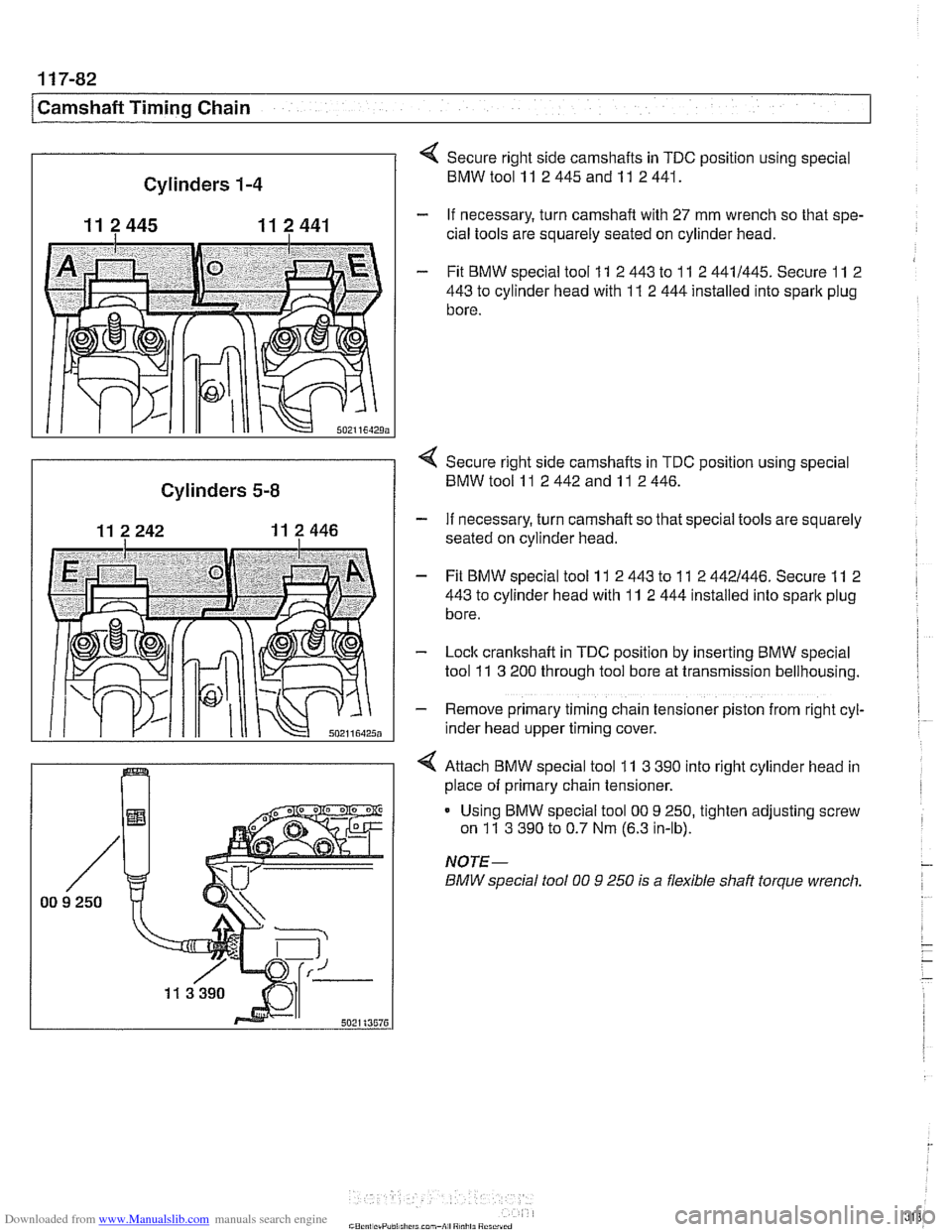
[camshaft Timina Chain Cylinders
1-4
11 2445 11 2 441
502116429;
Secure right side camshafts in TDC position using special
BMWtoolll 2445andll 2441.
- If necessary, turn camshaft with 27 mm wrench so that spe-
cial tools are squarely seated on cylinder head.
- Fit BMW special tool 11 2 443 to 11 2 4411445. Secure 11 2
443
to cylinder head with 11 2 444 installed into spark plug
bore.
I
< Secure right side camshafts in TDC position using special
Cylinders 5-8 BMW tool 11 2 442 and 11 2 446.
- If necessary, turn camshaft so that special tools are squarely
seated on cylinder head.
- Fit BMW special tool 11 2 443 to 11 2 4421446. Secure 11 2
443
to cylinder head with 11 2 444 installed into spark plug
bore.
- Lock cranltshaft in TDC position by inserting BMW special
tool
11 3 200 through tool bore at transmission bellhousing.
- Remove primary timing chain tensioner piston from right cyl-
~nder head upper timing cover.
4 Attach BMW special tool 11 3 390 into right cylinder head in
place of primary chain tensioner.
Using BMW special tool
00 9 250, tighten adjusting screw
on
11 3 390 to 0.7 Nm (6.3 in-lb).
NOTE-
BMW special fool 00 9 250 is a flexible shaft torque wrench.
Page 665 of 1002
Downloaded from www.Manualslib.com manuals search engine
320-7
Steering and Wheel ~liqnmentl
STEERING WHEEL
Steering wheel, removal and installation
WARNING -
The BMWairbag system (Supplemental Restraint System or
SRS) is complex. Special precautions must be observed
when servicing. Serious injury may result if
SRS system serv-
ice is
attempted by persons unfamiliar with the BMW SRS
and its approved service procedures. BMW specifies that all
inspection andservice should be preformed by an authorized
BMW dealer.
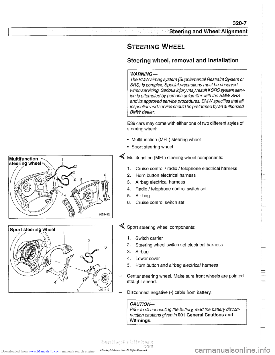
E39 cars may come with either one of two different styles of
steering wheel:
Multifunction (MFL) steering wheel
* Sport steering wheel
4 Multifunction (MFL) steering wheel components:
1. Cruise control 1 radio 1 telephone electrical harness
2. Horn button electrical harness
3. Airbag electrical harness
4. Radio / telephone control switch set
5. Air bag
6. Cruise control switch set
Sport steering wheel
3
5 0021413
4 Sport steering wheel components:
1. Switch carrier
2 Steering wheel switch set electrical harness
3. Airbag
4. Lower cover
5. Horn button and airbag electrical harness
- Center steering wheel. Make sure front wheels are pointed
straight ahead.
- Disconnect negative (-) cable from battery.
CA UTIOP&
Prior to disconnecting the battern read the battew discon-
nection cautions given in
001 General Cautions and
Warnings.
-
Page 678 of 1002
Downloaded from www.Manualslib.com manuals search engine
/steering and Wheel Alignment
Raise engine approximately 40 mm (1.6 in). See 110 Engine
Removal and installation.
Remove right and left engine mounts and remove mount
brackets from subframe.
Empty power steering fluid reservoir using a clean syringe.
Do not reuse power steering fluid.
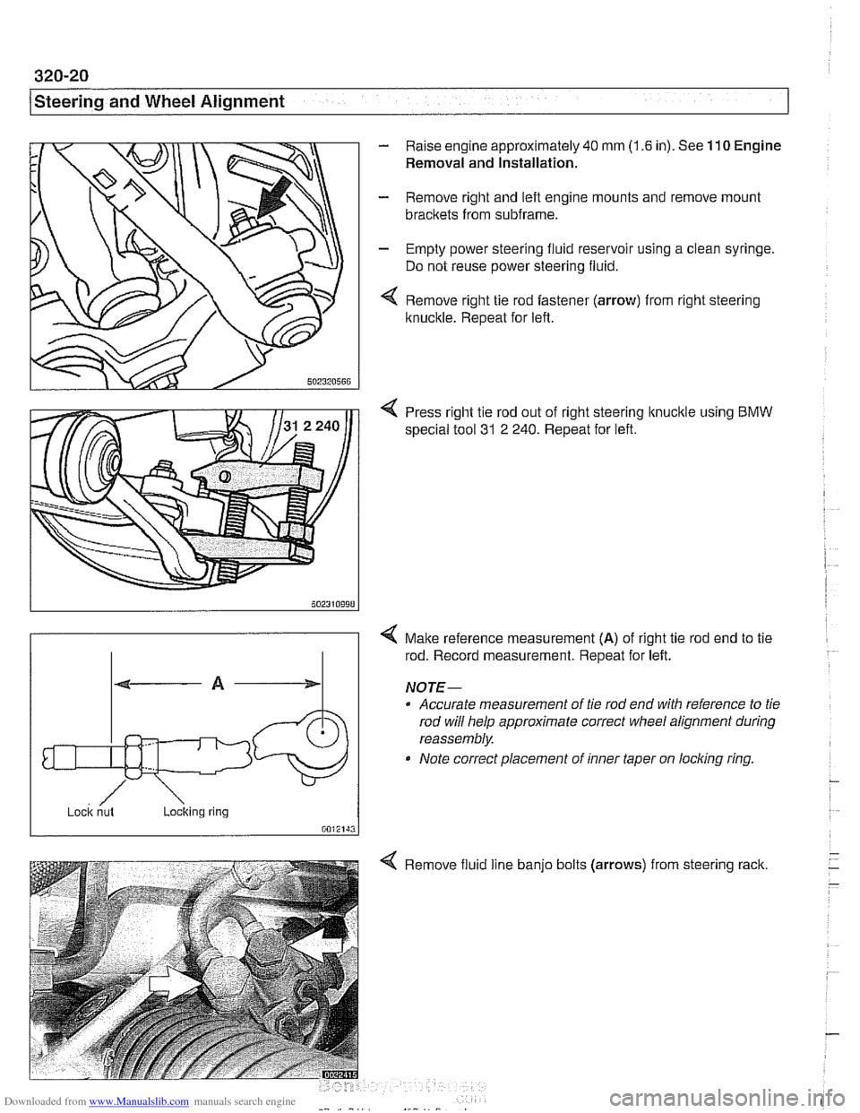
Remove right tie rod fastener (arrow) from right steering
Itnuckle. Repeat for left.
4 Press right tie rod out of right steering knucltle using BMW
special tool 31
2 240. Repeat for left.
/ ~ock nut Loclting ring
0012143
4 Malte reference measurement (A) of right tie rod end to tie
rod. Record measurement. Repeat for left.
NOJE-
0 Accurate measurement of tie rod end with reference to tie
rod will help approximate correct wheel alignment during
reassembly.
Note correct placement of inner taper on
locling ring
Remove fluid line
banjo bolts (arrows)
from steering rack.
Page 975 of 1002
Downloaded from www.Manualslib.com manuals search engine
OBD-15
On-Board ~iagnosticsl
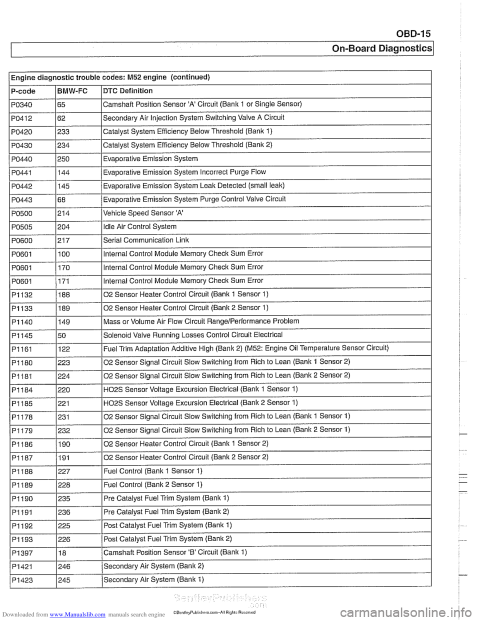
Engine diagnostic trouble codes: M52 engine (continued)
P-code
PO340
PO412
PO420
PO430
PO440
PO441
PO442
PO443
PO500
PO505
PO600
PO601
PO601
I PO601
~1132
~1133
BMW-FC
65
62
233
234
250 144
-
145
68
214
i I
DTC Definition
Camshalt Position Sensor 'A' Circuit (Bank 1 or Single Sensor)
Secondary Air Injection System Switching Valve A Circuit
Catalyst System Efficiency Below Threshold
(Bank 1)
Catalyst System Efficiency Below Threshold (Bank 2)
Evaporative Emission System
Eva~orative Emission Svstem Incorrect Purge Flow .
Evaporative Emission System Leak Detected (small leak)
Evaporative Emission System Purge Control Valve Circuit
Vehicle Speed Sensor 'A'
204
21 7
100
170
171
188
189
PI161
PI180
PI181
PI184
PI185
PI178
02 Sensor Heater Control Circuit (Bank 2 Sensor 2) I
idle Air Control System
Serial Communication
Link
Internal Control Module Memory Check Sum Error
Internal Control Module Memory
Check Sum Error
Internal Control Module Memory
Check Sum Error
02 Sensor Heater Control Circuit (Bank 1 Sensor
1)
02 Sensor Heater Control Circuit (Bank 2 Sensor 1)
Mass or Volume Air Flow Circuit RangeIPerlormance Problem PI140
I
I I
P1188 1227 I Fuel Control (Bank 1 Sensor 1)
PI145 150 /Solenoid Valve Running Losses Control Circuit Electrical
149
122
223
224
220 221
231
I I
P1189 1228 I Fuel Control (Banlc 2 Sensor 1)
Fuel Trim Adaptation Additive High (Bank 2) (M52: Engine Oil Temperature Sensor Circuit)
02 Sensor Signal Circuit Slow Switching from Rich to Lean
(Bank 1 Sensor 2)
02 Sensor Signal Circuit Slow Switching from Rich to Lean
(Bank 2 Sensor 2)
H02S Sensor Voltage Excursion Electrical (Banlc 1 Sensor 1)
HO2S Sensor Voltage Excursion Electrical (Banlc 2 Sensor 1)
02 Sensor Sianai Circuit Slow Switchina from Rich to Lean (Bank 1 Sensor 1)
02 Sensor Signal Circuit Slow Switching from Rich to Lean (Bank 2 Sensor 1) PI179
I I
PI190 1235 I Pre Catalyst Fuel Trim System (Banlc 1)
PI186 1190 102 Sensor Heater Control Circuit (Banlc 1 Sensor 2)
232
I I
PI191 1236 I Pre
Catalyst Fuel Trim System (Banlc 2)
PI192
. . -- - i Pi193 1226 I Post Catalvst Fuel Trim Svstem (Bank 2)
225
PI397
I I
Post Catalyst Fuel Trim System (Bank 1)
PI421 1246 /Secondarv Air System (Bank 2)
18
Secondary Air System (Bank
1) PI423
Camshaft Position Sensor '0' Circuit (Bank 1)
I 245
Page 980 of 1002
Downloaded from www.Manualslib.com manuals search engine
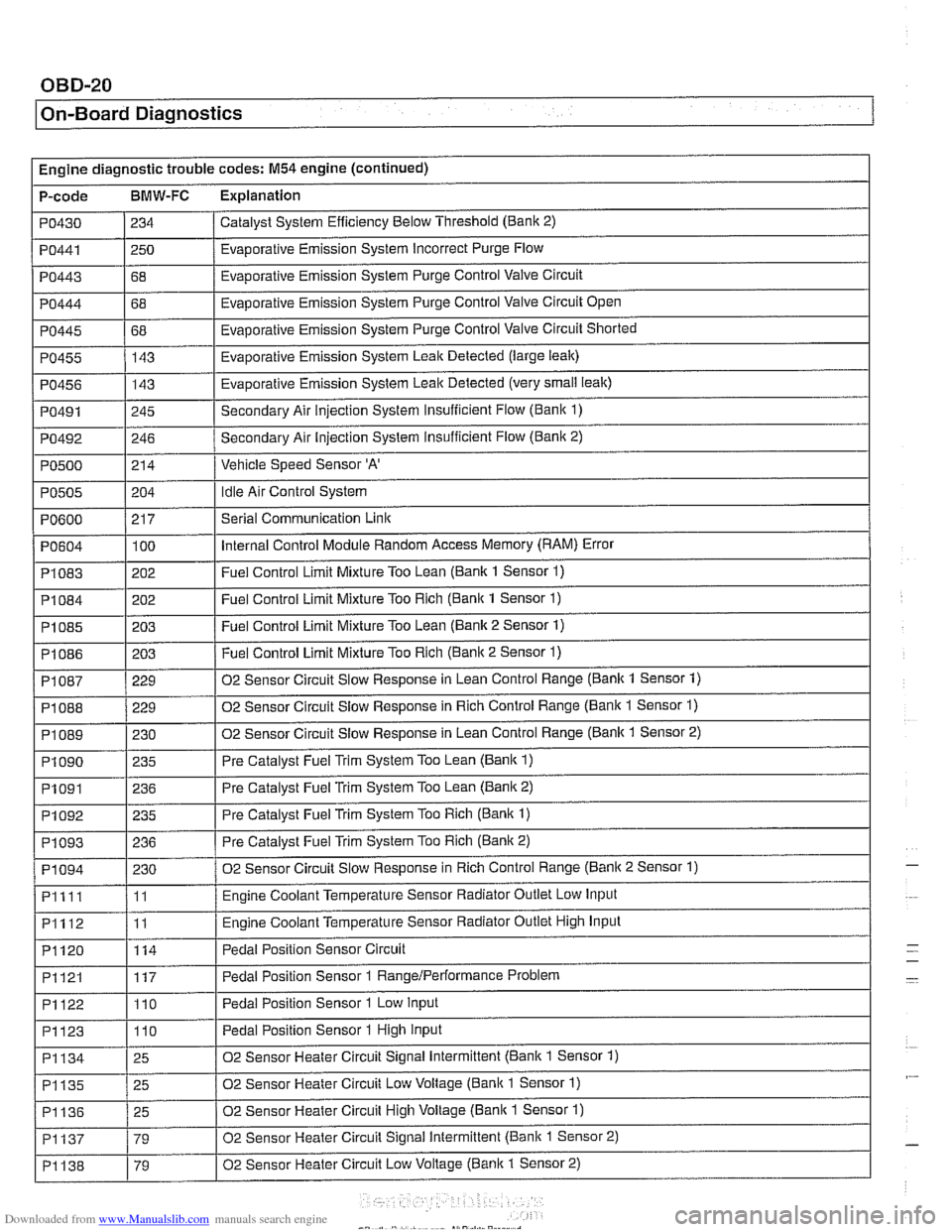
I On-Board Diagnostics
Engine diagnostic trouble codes: M54 engine (continued)
P-code
BMW-FC Explanation
Catalyst System Efficiency Below Threshold (Bank 2)
PO430
PO443
PO444
PO445
PO455
PO456
PO491
PO492
PO500
PO441 1250 / Evaporative Emission System Incorrect Purge Flow
234
I I
68
68
68 143
143
245
246
214
PO604
PI083
PI084
PI085
PI086
Evaporative Emission System Purge Control Valve Circuit
Evaporative Emission System Purge Control Valve Circuit Open
Evaporative Emission System Purge Control Valve Circuit Shorted
Evaporative Emission System Leak Detected (large leak)
Evaporative Emission System Leak Detected (very
small leak)
Secondary Air injection System Insufficient Flow (Bani( 1)
Secondary Air Injection System insufficient Flow
(Banic 2)
Vehicle Speed Sensor
'A'
Idle Air Control System PO505
.
PI 087
PI 088
PI089
PI090
PO600 / 217 I Serial Communication Link
204
100
202
202
203
203
PI091
PI092
PI093
PI094
Pllll
PI112
PI120
Internal Control Module Random Access Memory (RAM) Error
Fuel Control Limit Mixture Too Lean (Bank 1 Sensor
1)
Fuel Control Limit Mixture Too Rich (Bank 1 Sensor 1)
Fuel Control Limit Mixture Too Lean (Bank 2 Sensor 1)
Fuel Control Limit Mixture Too Rich (Banic 2 Sensor 1) ~ ~
229
229
230 235
PI121
PI122
PI123
02 Sensor Circuit Slow Response in Lean Control Range (Bank 1 Sensor 1)
02 Sensor Circuit Slow Response in Rich Control Range (Bank 1 Sensor
1)
02 Sensor Circuit Slow Response in Lean Control Range (Banlc 1 Sensor 2)
Pre Catalyst Fuel Trim System Too Lean
(Bank 1)
236
235
236
230
11
11
114
PI134
PI135
PI136
PI137
PI138
Pre Catalyst Fuel Trim System Too Lean (Banic 2)
Pre Catalyst Fuel Trim System Too Rich
(Bank 1)
Pre Catalyst Fuel Trim System Too Rich (Bank 2)
02 Sensor Circuit Slow Response in Rich Control Range (Banic 2 Sensor 1)
Engine Coolant Temperature Sensor Radiator Outlet Low Input
Engine Coolant Temperature Sensor Radiator Outlet High Input
Pedal Position Sensor Circuit
117
110
110
25
25
25
79
79 Pedal Position Sensor 1
RangeIPerformance Problem
Pedal Position Sensor 1 Low Input
Pedal Position Sensor 1 High Input
02 Sensor Heater Circuit Signal Intermittent (Bank 1 Sensor 1)
02 Sensor Heater Circuit Low Voltage (Bank 1 Sensor
1)
02 Sensor Heater Circuit High Voltage (Bank 1 Sensor 1)
02 Sensor Heater Circuit Signal Intermittent (Bank 1 Sensor 2)
02 Sensor Heater Circuit Low Voltage
(Banic 1 Sensor 2)
-
-