611 BMW 530i 2001 E39 Workshop Manual
[x] Cancel search | Manufacturer: BMW, Model Year: 2001, Model line: 530i, Model: BMW 530i 2001 E39Pages: 1002
Page 3 of 1002

Downloaded from www.Manualslib.com manuals search engine
YOU are now in Volume I
I
Foreword ................... .. ........................................................................\
.......... v
Index
........................ .. ................................................................ rear of manual
General, 001 General Warnings and Cautions 002 Vehicle Identification and VIN Decoder
Maintenance OiO 020 Maintenance
Engine
100 Engine-General 110 Engine Removal and Installation
113 Cylinder Head Removal and
Installation
116 Cyiinder Head and Valvetrain 117 Camshaft Timing Chain
119 Lubrication System
200 Transmission-General
2 Transmission 210 clutch 230 ManualTransmission
I20 Ignition System
121 Battery, Starter, Alternator
130 Fuel Injection
160 Fuel Tank and Fuel Pump 170 Radiator and Cooling System
180 Exhaust System
240 Automatic Transmission
250 Gearshift Linkage 260 Driveshaft
Suspension, 300 Suspension, Steering and 330 Rear Suspension
Brakes-General 331 Final Drive
Steering and No Front Suspension 340 Brakes
320 Steering and Wheel Alignment
400 Body-General
410 Fenders, Engine Hood 411 Doors
412 Trunk Lid, Tailgate
510 Exterior Trim, Bumpers 512 Door Windows
Equipment 513 Interior Trim
7
Equipment and 720 seat Belts
Accessories 721 Airbag System (SRS)
OBD On-Board Diagnostics
. ............ ..
515 Central Lociting and
Anti-Theft
520 Seats 540 Sunroof
.................................................................... Foreword .............................. .. v
Index ................... .. ................................................................ rear of manual
Electrical
6 system
600 Electrical System-General 620 Instruments
610 Electrical Comoonent Locations 630 Liohts
611 wipers and washers 612 Switches eati in^ and Air Conditioning
Radio
. ........... ........ .........................
Electrical Wiring Diagrams
Page 98 of 1002
Downloaded from www.Manualslib.com manuals search engine
11 3-4
Cylinder Head Removal and Installation
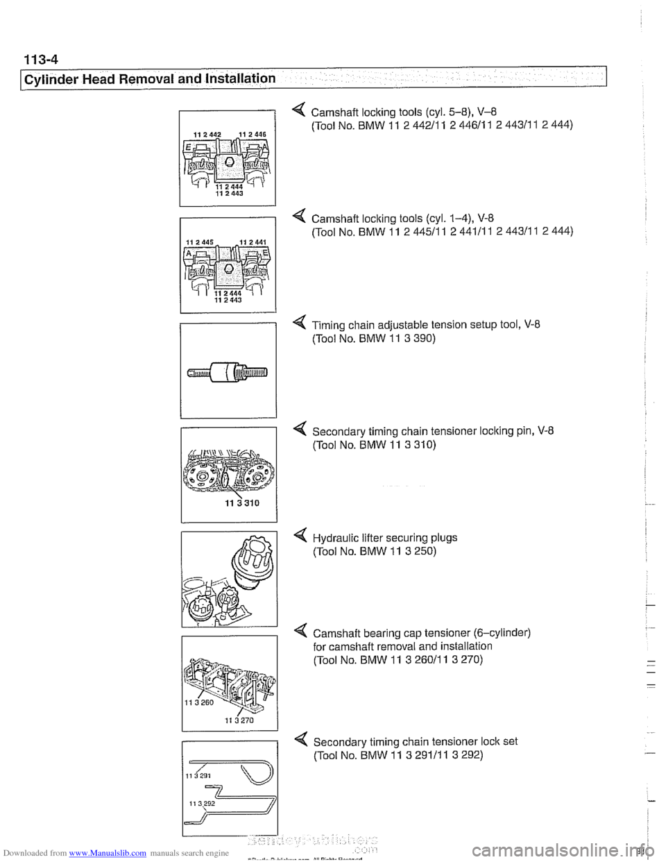
4 Camshaft locking tools (cyl. 5-8), V-8
112442 112446 (Tool No. BMW 11 2 44211 1 2 44611 1 2 44311 1 2 444)
4 Camshaft loclting tools (cyl. 1-4), V-8
(Tool No. BMW 11 2 44511
1 2 44111 1 2 44311 1 2 444)
4 Timing chain adjustable tension setup tool, V-8
(Tool No. BMW 11 3 390)
Secondary timing chain tensioner loclting pin, V-8
(Tool No. BMW 11 3 310)
4 Hydraulic lifter securing plugs
(Tool No. BMW 11 3 250)
< Camshaft bearing cap tensioner (6-cylinder)
for
camshaft removal and installation
(Tool No. BMW 11
3 26011 1 3 270)
4 Secondary timing chain tensioner loclt set
(Tool No. BMW 11 3 29111 1 3 292)
Page 639 of 1002
Downloaded from www.Manualslib.com manuals search engine
Front Suspension
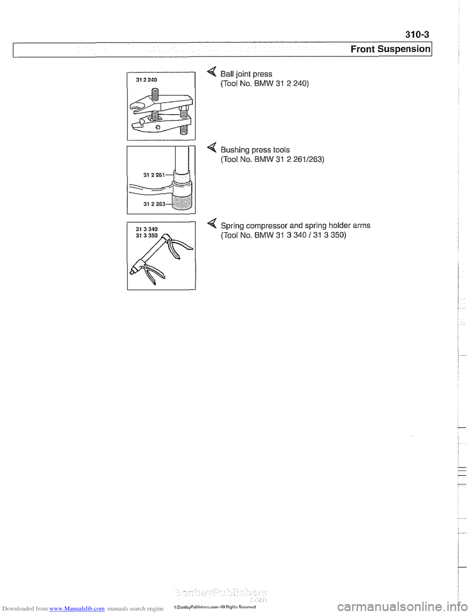
< Ball joint press
(Tool No. BMW
31 2 240)
< Bushing press tools
(Tool No. BMW
31 2 2611263)
4 Spring compressor and spring holder arms
31 3 350 (Tool No. BMW 31 3 340 131 3 350)
Page 654 of 1002
Downloaded from www.Manualslib.com manuals search engine
31 0-1 8
I~ront Suspension Tension strut bushing, replacing
- Raise car and remove wheel.
WARNING-
Make sure that the caris firmly supported on jack stands de-
signed for the purpose. Place jack stands underneath struc-
tural chassis points. Do
not place jack stands under
suspension parts.
- Remove tension strut from car as described earlier.
- Using a service press and appropriate press tools (BMW
special tools 31 2 26112621263 or equivalent), press bushing
out of tension strut.
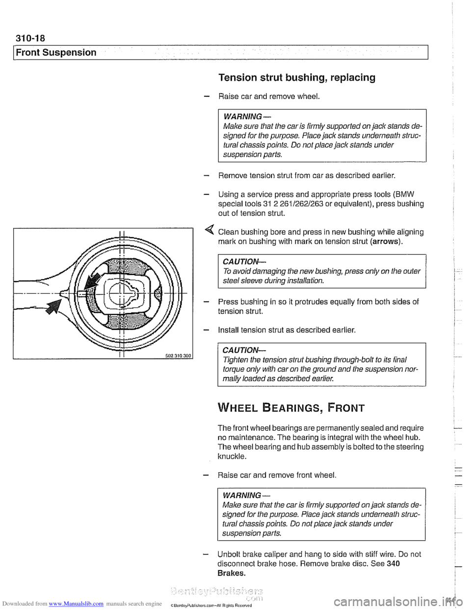
4 Clean bushing bore and press in new bushing while aligning
mark on bushing with
rnarlt on tension strut (arrows).
CAUTION-
To avoid damaging the new bushing, press only on the outer
steel sleeve during installation.
- Press bushing in so it protrudes equally from both sides of
tension strut.
- Install tension strut as described earlier.
CAUTION-
Tighten the tension strut bushing through-bolt to its final
torque only with car on the ground and the suspension nor-
mally loaded as described earlier.
The front wheel bearings are permanently sealed and require
no maintenance. The bearing is integral with the wheel hub.
The wheel bearing and hub assembly is bolted to the steering
knuckle.
- Raise car and remove front wheel
WARNING-
Make sure that the car is firmly supported on jack stands de-
signed for the purpose. Place jack stands underneath struc-
tural chassis points. Do not place
jack stands under
susoension Darts.
- Unbolt brake caliper and hang to side with stiff wire. Do not
disconnect bralte hose. Remove bralte disc. See
340
Brakes.
Page 761 of 1002
Downloaded from www.Manualslib.com manuals search engine
331-17
Final ~rivel
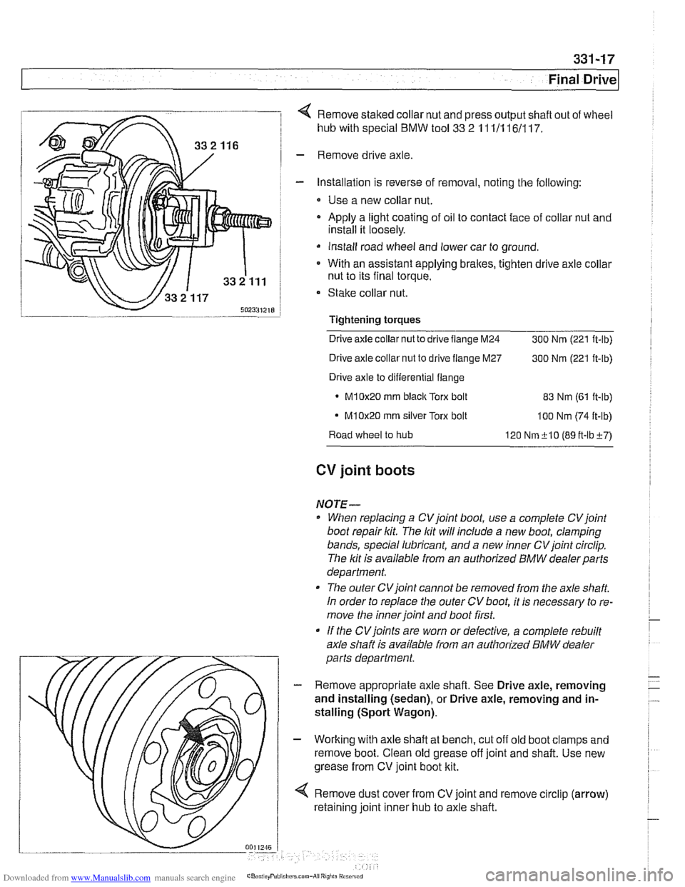
4 Remove staked collar nut and press output shaft out of wheel
hub with special
BMW tool 33 2 11 111 161117.
- Remove drive axle
- Installation is reverse of removal, noting the following:
* Use a new collar nut.
- Apply a light coating of oil to contact face of collar nut and
install it loosely.
Install road wheel and lower car to ground.
* With an assistant applying brakes, tighten drive axle collar
nut to its final torque.
Stake collar nut.
Tightening
torques
Drive axle collar nut to drive flange M24
300 Nrn (221 ft-lb)
Drive axle collar nut to drive flange M27
300 Nrn (221 ft-lb)
Drive axle to differential flange
M10x20 rnrn blaclc Torx bolt 83 Nrn (61 it-lb)
- M10x20 rnrn silver Torx bolt loo Nrn (74 ft-lb)
Road wheel to hub
120 Nrn+lO (89tt-lbi-7)
CV joint boots
NOTE-
When replacing a CVjoint boot, use a complete CVjoint
boot repair kit. The lit will include a new boot, clamping
bands, special lubricant, and a new inner CV joint circlip.
The lit is available from an authorized
BMW dealerparts
department.
The outer CVjoint cannot be removed from the axle
shaft
In order to replace the outer CV boot, it is necessary to re-
move the inner joint and boot first.
If the
CVjoints are worn or defective, a complete rebuilt
axle shaft is available from an authorized
BMW dealer
parts department.
- Remove appropriate axle shaft. See Drive axle, removing
and installing (sedan), or Drive axle, removing and in-
stalling (Sport Wagon).
- Working with axle shaft at bench, cut off old boot clamps and
remove boot. Clean old grease off joint and shaft. Use new
grease from CV joint boot kit.
4 Remove dust cover from CV joint and remove circlip (arrow)
retaining joint inner hub to axle shaft.
Page 805 of 1002
Downloaded from www.Manualslib.com manuals search engine
Instrument cluster
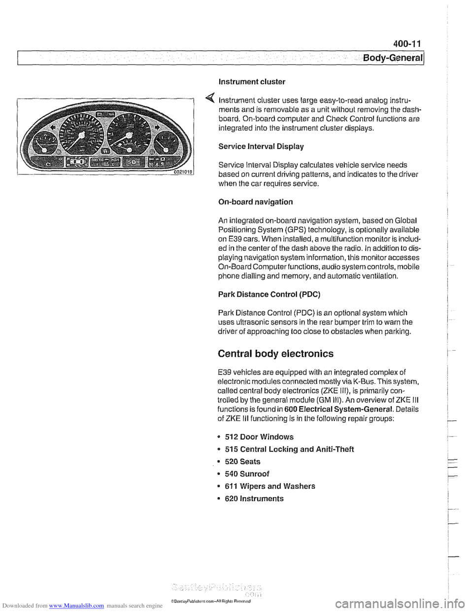
Instrument cluster uses large easy-to-read analog instru-
ments and is removable as a unit without removing the dash-
board. On-board computer and Check Control functions are
integrated into the instrument cluster displays.
Service Interval Display
Service Interval Display calculates vehicle service needs
based on current driving patterns, and indicates to the driver
when the car requires
service
On-board navigation
An integrated on-board navigation system, based on Global
Positioning System (GPS) technology, is optionally available
on
E39 cars. When installed, a multifunction monitor is includ-
ed in the center of the dash above the radio. in addition to dis-
playing navigation system information, this monitor accesses
On-Board Computerfunctions, audiosystem controls, mobile
phone dialling and memory, and automatic ventilation.
Park Distance Control (PDC)
Park Distance Control (PDC) is an optional system which
uses ultrasonic sensors in the rear bumper trim to warn the
driver of approaching too close to obstacles when parlting.
Central body electronics
E39 vehicles are equipped with an integrated complex of
electronic modules connected mostly via K-Bus. This system,
called central body electronics (ZKE
Ill), is primarily con-
trolled by the general module (GM
Ill). An overview of ZKE Ill
functions is found in 600 Electrical System-General. Details
of ZKE
Ill functioning is in the following repair groups:
- 512 Door Windows
* 515 Central Locking and Aniti-Theft
520 Seats
a 540 Sunroof
611 Wipers and Washers
620 Instruments
Page 850 of 1002
Downloaded from www.Manualslib.com manuals search engine
41 2-22
1 Trunk Lid, Tailgate
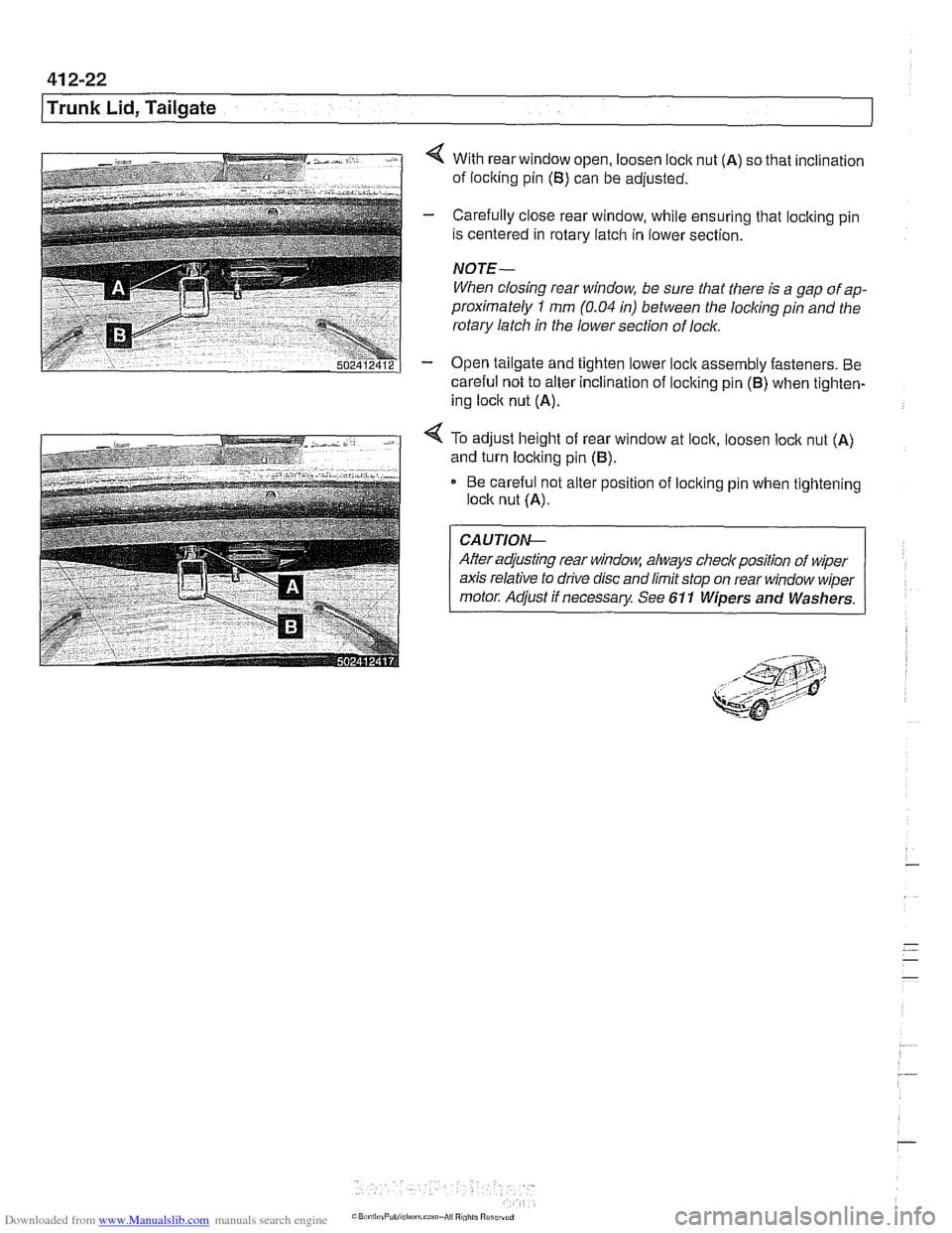
4 With rear window open, loosen loclc nut (A) so that inclination
of loclting pin
(B) can be adjusted.
- Carefully close rear window, while ensuring that locking pin
is centered in rotary latch in lower section.
NOTE-
When closing rear window, be sure that there is a gap of ap-
proximately
1 mm (0.04 in) between the locliing pin and the
rotary latch in the lower section of lock.
- Open tailgate and tighten lower loclc assembly fasteners. Be
careful not to alter inclination of loclting pin
(B) when tighten-
ing loclc nut
(A).
4 To adjust height of rear window at lock, loosen loclc nut (A)
and turn locking pin (B).
Be careful not alter position of loclting pin when tightening
lock nut
(A).
CA UTIOG
After adjusting rear window, always checlr position of wiper
axis relative to drive disc and limit stop on rear window wiper
motor. Adjust if necessary See 611 Wipers and Washers.
Page 864 of 1002
Downloaded from www.Manualslib.com manuals search engine
Exterior Trim, Bumpers 1
Radiator grill, removing and installing
- Open hood
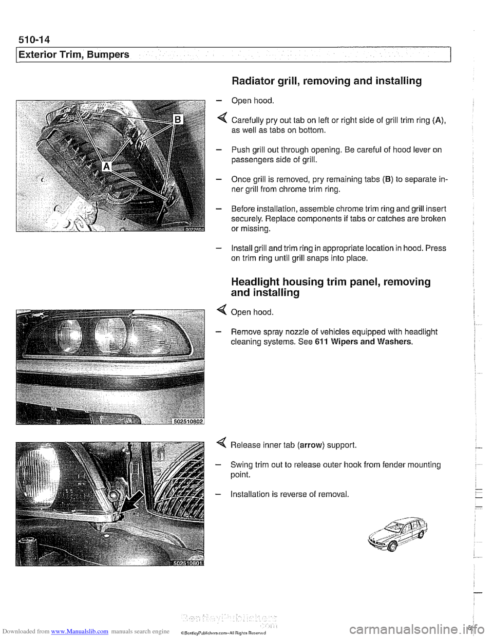
4 Carefully pry out tab on lefl or right side of grill trim ring (A),
as well as tabs on bottom.
- Push grill out through opening. Be careful of hood lever on
passengers side of grill.
- Once grill is removed, pry remaining tabs (B) to separate in-
ner grill from chrome trim ring.
- Before installation, assemble chrome trim ring and grill insert
securely. Replace components
if tabs or catches are brolten
or missing.
- Install grill and trim ring in appropriate location in hood. Press
on trim ring until grill snaps into place.
Headlight housing trim panel, removing
and installing
4 Open hood
- Remove spray nozzle of vehicles equipped with headlight
cleaning systems. See
611 Wipers and Washers.
Release inner tab (arrow) support.
Swing trim out to release outer hook
point. from fender mounting
Installation is reverse of removal
Page 996 of 1002
Downloaded from www.Manualslib.com manuals search engine
Gaskets and seals 01
0-9
Gearshift automatic transmission
adjusting
250-7
shift interiock. checkino function " 250-9
shiftloclc. checicino function 250-8 - manual transmission
gearshift lever, removingiinstalling
250-5
steptronic 250-7
General module (GM Ill)
600-8
see also Central locking
Generator see Battery, starter, alternator
Glass see Door window
Glove compartment
513-16
see also
Global positioning system
(GPS)
620-9
Grill
see Exterior trim
Grounds
100-5
Guide link
see Rear suspension, suspension
arms
Halogen headlight
630-5
Hand brake
see Brakes, pariring brake
Handle, door
see Door
locks
Hatch seeTailgate
Hazard warning switch
see Switches Headlight
housing trim
see Exterior trim
washer611-17 see also Lights
Headlight spray
nozzle
611-17
Headlight switch
see Switches
Heater core
see Heating
Heater valve
see Heating
Heating lieater core, replacing
640-18
lheater core temperature sensor,
removingiinstalling
640-12 heater valve, replacing 640-17
IHKA housing, removinglinstallin~
640-21
see also NC
Hood
410-6
Hood latch and release
410-10
Hydraulic valve lifters
see Cylinder head and valvetrain
IAT
(lntalce air temperature) sensor
see 130
under appropriate fuel
injection system
idle speed control valve
see 130
under appropriate fuel injection system
Idle stabilizer
see 130
under appropriate fuel
injection system, idie speed controi
valve
idler arm
320-30
lgnition coll
see lgnition system
lgnition interlock
320-13
lgnition lock cylinder
removingiinstalling
320-1 1. 612-4
lgnition switch
seeSwifches
Ignition system
diagnosis checking for
spark 120-10
disabling ignition system 120-10 misfire detection 120-6
oscilioscope diagrams 120.6
troubleshooting 120-6
camshaft position sensors 120-14 coils 120.10
crankshaft speed sensor 120-12 firing order 120-9
knoclc sensors 120-16
IHKA
see NC
IHKR see NC
Injector
see 130 under appropriate
fuel
injection system, luel injector
Input shaft
oil seal
see Manual transmission, oil seals
Inspection
see Maintenance
Instruments GPS see Global positioning system
(GPSI layout 6202
removingiinstalling 620-8 self-testing 620-6
Intake air temperature sensor (IAT)
see 130 under appropriate fuel
injection system
Intake manifold
removingiinstalling
6-cvlinder enoine 110-10. 113-8. 113-22 -
V-8 engine (M62) 113-56
Integral link
see Rear suspension, suspension
arms
lnterior lights
see Lights
lnterior protection
(FISIUIS) 515-25
lnterior trim
513-13
lnterior ventilation microfilter see
NC, ventilation microfiller
Page 998 of 1002
Downloaded from www.Manualslib.com manuals search engine
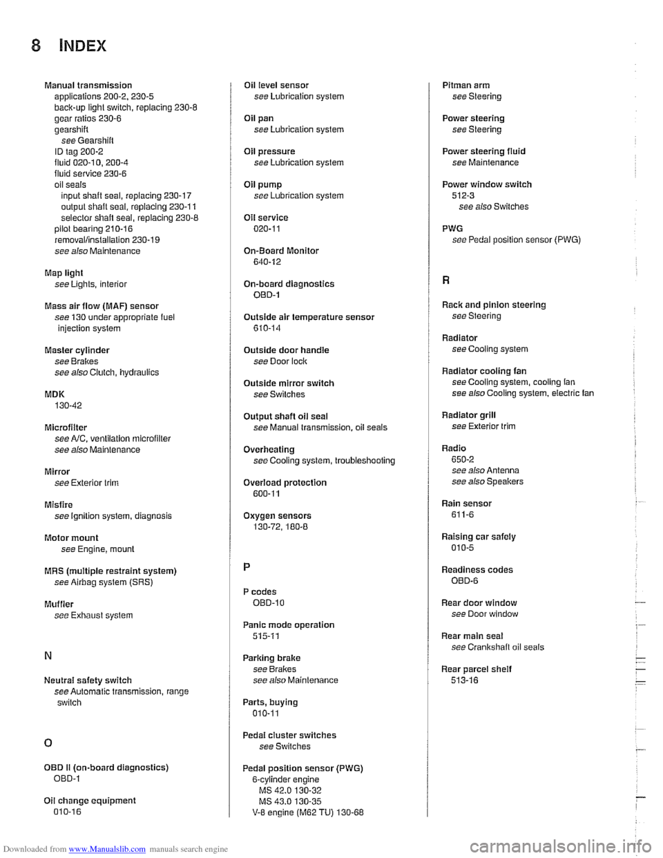
Manual transmission
applications 200-2. 230-5
back-up light switch, replacing 230-6
gear ratios 230-6
gearshift
see Gearshiit
ID tag 200-2
fluid 020-1 0. 200-4 fluid service 230-6
oil seals
input shaft seal, replacing
230-17
output shalt seal, replacing 230-1 1
selector
shaft seal, replacing 230-8 pilot bearing 210-16
removallinstallation 230-19
see also Maintenance
Map light
see Lights, interior
Mass air flow
(MAF) sensor
see 130 under appropriate fuel
injection syslem
Master cylinder
see Brakes
see also Clutch, hydraulics
MDK
130-42
Microfilter see
NC, ventilation microfilter
see also Maintenance
Mirror see Exterior trim
Misfire see Ignition syslem, diagnosis
Motor mount
see Engine,
mounl
MRS (multiple restraint system)
see Airbag system (SRS)
Muffler
see Exhaust syslem
Neutral safety switch
see Automatic transmission, range
switch
OED II (on-board diagnostics)
OED-l
Oil change equipment 010-16
Oil level sensor
see Lubrication system
Oil pan
see Lubrication system
OH pressure
see Lubrication system
Oil pump
see Lubrication system
Oil service 020-1 1
On-Board Monitor
640-12
On-board diagnostics OED-1
Outside air temperature sensor
610-14
Outside door handle
see Door
loclc
Outside mirror switch
see Switches
Output
shaft oil seal
see Manual transmission, oil seals
Overheating
see Cooling system, troubleshooting
Overload protection
600-11
Oxygen sensors
130-72, 180-8
P codes OED-10
Panic mode operation
515-11
Parking brake
see Brakes
see also Maintenance
Parts, buying
010-11
Pedal cluster switches
see Switches
Pedal position sensor (PWG)
6-cvlinder
enqine
V-8 engine (M62 TU) 130-68
Pitman arm
see Steering
Power steering
see Steering
Power steering
fluid
see Maintenance
Power window switch
512-3 see also Switches
PWG see Pedal position sensor
(PWG)
Racic and pinion steering
see Steering
Radiator see Cooling system
Radiator cooling fan seeCooling system, cooling fan
see also Cooling system, electric fan
Radiator grill
see Exterior
trim
Radio
650-2 see also Antenna
see also Speakers
Rain sensor
611-6
Raising car safely
010-5
Readiness codes
OED-6
Rear door window
see Door window
Rear main seal
see Crankshalt oil seals
Rear parcel
sheif
513-16