Limit light BMW 535D 2014 Owner's Manual
[x] Cancel search | Manufacturer: BMW, Model Year: 2014, Model line: 535D, Model: BMW 535D 2014Pages: 267, PDF Size: 5.88 MB
Page 142 of 267
otherwise, there is the danger of an accident
occurring.◀
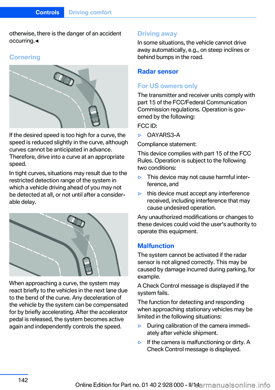
Cornering
If the desired speed is too high for a curve, the
speed is reduced slightly in the curve, although
curves cannot be anticipated in advance.
Therefore, drive into a curve at an appropriate
speed.
In tight curves, situations may result due to the
restricted detection range of the system in
which a vehicle driving ahead of you may not
be detected at all, or not until after a consider‐
able delay.
When approaching a curve, the system may
react briefly to the vehicles in the next lane due
to the bend of the curve. Any deceleration of
the vehicle by the system can be compensated
for by briefly accelerating. After the accelerator
pedal is released, the system becomes active
again and independently controls the speed.
Driving away
In some situations, the vehicle cannot drive
away automatically, e.g., on steep inclines or
behind bumps in the road.
Radar sensor
For US owners only
The transmitter and receiver units comply with
part 15 of the FCC/Federal Communication
Commission regulations. Operation is gov‐
erned by the following:
FCC ID:▷OAYARS3-A
Compliance statement:
This device complies with part 15 of the FCC
Rules. Operation is subject to the following
two conditions:
▷This device may not cause harmful inter‐
ference, and▷this device must accept any interference
received, including interference that may
cause undesired operation.
Any unauthorized modifications or changes to
these devices could void the user's authority to
operate this equipment.
Malfunction
The system cannot be activated if the radar sensor is not aligned correctly. This may be
caused by damage incurred during parking, for
example.
A Check Control message is displayed if the
system fails.
The function for detecting and responding
when approaching stationary vehicles may be limited in the following situations:
▷During calibration of the camera immedi‐
ately after vehicle shipment.▷If the camera is malfunctioning or dirty. A
Check Control message is displayed.Seite 142ControlsDriving comfort142
Online Edition for Part no. 01 40 2 928 000 - II/14
Page 143 of 267
Traffic Jam AssistThe concept
In congestion situations, the system controls
the speed, steers independently as required
and keeps the vehicle close to the center of
the lane.
To the extent possible, the system automati‐
cally adjusts the speed to a slower vehicle
ahead of you. The distance that the vehicle
maintains to the vehicle ahead of you can be
varied. For safety reasons, it depends on the
speed. To maintain a certain distance, the sys‐
tem automatically reduces the speed, applies
the brakes lightly, or accelerates again if the
vehicle ahead begins moving faster.
When lane markings are detected, the system
keeps the vehicle in the center of the lane. For
this purpose, the system steers independently
as needed, for example, during cornering.
General information
The congestion assistant determines speed
and distance from the vehicle in front and the
position of the lane markings via a radar sensor
and a camera.
Sensors on the steering wheel detect whether
the steering wheel is being touched.
The system is deactivated as soon as the
steering wheel is no longer being touched.
In order to be able to use the Congestion As‐
sistant, place your hands around the steering
wheel.
When driving with gloves or with protective
covers, contact with the steering wheel cannot
be detected by the sensors. The system in this
case cannot be used.
Hints Personal responsibility
Even an active system does not release
the driver from personal responsibility for the
driving process, especially for lane tracking,adaptation of speed, distance and driving style
to the traffic conditions.
Because of technical system limits, the system
cannot independently react appropriately in all
traffic situations.
Monitor the driving process, the surrounding
area and what is occurring in traffic continu‐
ously and attentively and actively intervene as
required, e.g., by braking, steering or making
an evasive maneuver.◀
Unfavorable weather conditions
In the event of unfavorable weather and
light conditions, e. g. if there is rain, snowfall,
slush, fog or glare, this may result in poorer
recognition of vehicles as well as short-term
interruptions for vehicles and lane markings
that are already detected. Drive attentively, and
react to the current traffic events. Intervene ac‐
tively when necessary, e.g., by braking, steer‐
ing or making an evasive maneuver, otherwise,
there is danger of an accident.◀
Functional requirements▷Drive on approved road type. The data on
this are stored in the navigation system.
Approved road types are highways.▷Sufficient lane width.▷Lane marking on both sides is detected.▷Vehicle driving ahead is detected.▷Speed below 25 mph/40 km/h.▷Both hands on the steering wheel rim.▷Sufficient curvature.▷Drive in the center of the lane.Seite 143Driving comfortControls143
Online Edition for Part no. 01 40 2 928 000 - II/14
Page 149 of 267
▷Keep the sensors clean and free of ice.▷When using high-pressure washers, do not
spray the sensors for long periods and
maintain a distance of at least 12 in/30 cm.
Hints
Personal responsibility
Even an active system does not relieve
the driver from personal responsibility for the
driving process.
Because of technical system limits, the system
cannot independently react appropriately in all
traffic situations.
Continuously and attentively monitor the driv‐
ing process, the area surrounding the vehicle
and the traffic situation, and actively intervene
when required, otherwise, there is a risk of an
accident.◀
Avoid driving quickly with PDC
Avoid approaching an object quickly.
Avoid driving away quickly while PDC is not yet
active.
For technical reasons, the system may other‐
wise be too late in issuing a warning.◀
At a glance
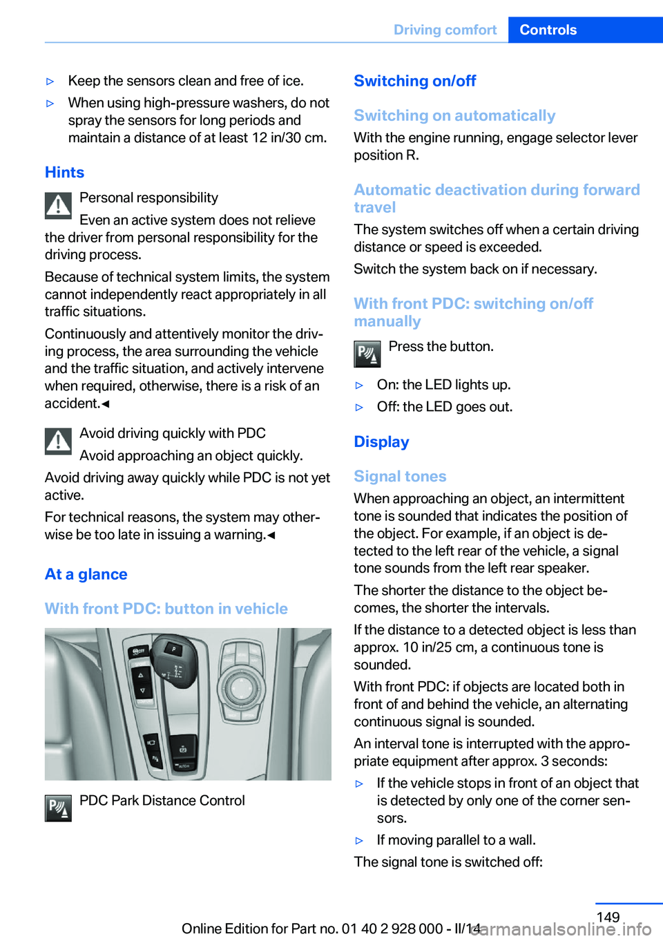
With front PDC: button in vehicle
PDC Park Distance Control
Switching on/off
Switching on automatically With the engine running, engage selector lever
position R.
Automatic deactivation during forward
travel
The system switches off when a certain driving
distance or speed is exceeded.
Switch the system back on if necessary.
With front PDC: switching on/off
manually
Press the button.▷On: the LED lights up.▷Off: the LED goes out.
Display
Signal tones When approaching an object, an intermittent
tone is sounded that indicates the position of
the object. For example, if an object is de‐
tected to the left rear of the vehicle, a signal
tone sounds from the left rear speaker.
The shorter the distance to the object be‐
comes, the shorter the intervals.
If the distance to a detected object is less than
approx. 10 in/25 cm, a continuous tone is
sounded.
With front PDC: if objects are located both in
front of and behind the vehicle, an alternating
continuous signal is sounded.
An interval tone is interrupted with the appro‐
priate equipment after approx. 3 seconds:
▷If the vehicle stops in front of an object that
is detected by only one of the corner sen‐
sors.▷If moving parallel to a wall.
The signal tone is switched off:
Seite 149Driving comfortControls149
Online Edition for Part no. 01 40 2 928 000 - II/14
Page 150 of 267
▷When the vehicle moves away from an ob‐
ject by more than approx. 4 in/10 cm.▷When selector lever position P is engaged
on vehicles with automatic transmission.
Volume
The volume of the PDC signal tone can be ad‐
justed similar to the tone and volume settings
of the radio.
The setting is stored for the remote control
currently in use.
Visual warning
The approach of the vehicle to an object can
be shown on the Control Display. Objects that
are farther away are displayed on the Control
Display before a signal tone sounds.
A display appears as soon as Park Distance
Control (PDC) is activated.
The range of the sensors is represented in the
colors red, green and yellow.
When the image of the rearview camera is dis‐
played, the switch can be made to PDC:
"Rear view camera"
System limits
Limits of ultrasonic measurement The detection of objects can reach the physi‐
cal limits of ultrasonic measurement, e.g., in
the following circumstances:
▷For small children and animals.▷For persons with certain clothing, e.g.
coats.▷If there is an external disturbance of the ul‐
trasound, e.g. from passing vehicles or
loud machines.▷When sensors are dirty, iced over, dam‐
aged or out of position.▷Under certain weather conditions, such as
high relative humidity, rain, snowfall ex‐
treme heat or strong wind.▷With tow bars and trailer hitches of other
vehicles.▷With thin or wedge-shaped objects.▷With moving objects.▷With elevated, protruding objects such as
ledges or cargo.▷With objects with corners and sharp edges.▷With objects with a fine surface structure,
such as fences.▷For objects with porous surfaces.
Low objects already displayed, e.g., curbs, can
move into the blind area of the sensors before
or after a continuous tone sounds.
False warnings
PDC may issue a warning under the following conditions even though there is no obstacle
within the detection range:
▷In heavy rain.▷When sensors are very dirty or covered in
ice.▷When sensors are covered in snow.▷On rough road surfaces.▷On uneven surfaces, such as speed
bumps.▷In large buildings with right angles and
smooth walls, e.g., in underground ga‐
rages.▷In heavy exhaust.▷Due to other ultrasound sources, e.g.,
sweeping machines, high pressure steam
cleaners or neon lights.
Malfunction
A Check Control message is displayed.
The range of the sensors is shown as a shaded
area on the Control Display.
PDC has failed. Have the system checked.
To ensure full operability:
▷Keep the sensors clean and free of ice.Seite 150ControlsDriving comfort150
Online Edition for Part no. 01 40 2 928 000 - II/14
Page 156 of 267
Switching on/off
Switching on automatically With the engine running, engage selector lever
position R.
The Top View and PDC images are displayed if
the system is switched on via iDrive.
Automatic deactivation during forward
travel
The system switches off when a certain driving
distance or speed is exceeded.
Switch the system back on if necessary.
Switching on/off manually Press the button.▷On: the LED lights up.▷Off: the LED goes out.
Top View is displayed.
Display
Visual warning
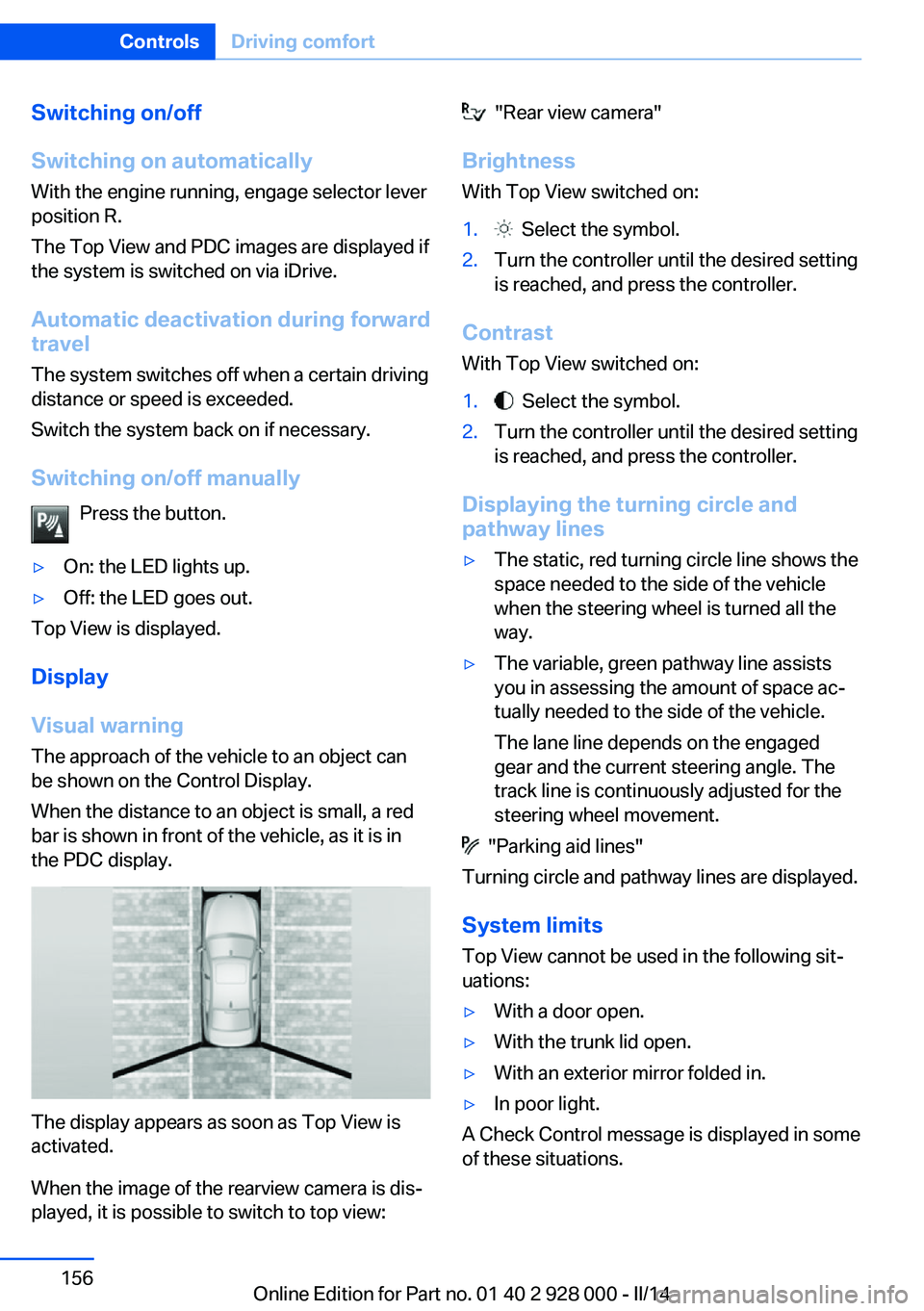
The approach of the vehicle to an object can
be shown on the Control Display.
When the distance to an object is small, a red
bar is shown in front of the vehicle, as it is in
the PDC display.
The display appears as soon as Top View is
activated.
When the image of the rearview camera is dis‐
played, it is possible to switch to top view:
"Rear view camera"
Brightness With Top View switched on:1. Select the symbol.2.Turn the controller until the desired setting
is reached, and press the controller.
Contrast
With Top View switched on:
1. Select the symbol.2.Turn the controller until the desired setting
is reached, and press the controller.
Displaying the turning circle and
pathway lines
▷The static, red turning circle line shows the
space needed to the side of the vehicle
when the steering wheel is turned all the
way.▷The variable, green pathway line assists
you in assessing the amount of space ac‐
tually needed to the side of the vehicle.
The lane line depends on the engaged
gear and the current steering angle. The
track line is continuously adjusted for the
steering wheel movement.
"Parking aid lines"
Turning circle and pathway lines are displayed.
System limits
Top View cannot be used in the following sit‐
uations:
▷With a door open.▷With the trunk lid open.▷With an exterior mirror folded in.▷In poor light.
A Check Control message is displayed in some
of these situations.
Seite 156ControlsDriving comfort156
Online Edition for Part no. 01 40 2 928 000 - II/14
Page 176 of 267
middle section is folded down. Otherwise, in‐
jury or damage may result.◀
Ensuring the stability of the child seat
When installing child restraint fixing sys‐
tems, make sure that the child seat is securely
fastened to the backrest of the seat. The angle
of the backrest may need to be adjusted and,
where necessary, the headrest height may also
need to be adjusted, or if possible removed.
Make sure that all backrests are securely
locked. Otherwise, the stability of the child
seat is limited, and there is an increased risk of
injury because of unexpected movement of the
rear seat backrest.◀
Opening Move the front seats to an upright posi‐
tion
Before folding down the rear backrests, ensure
that the front seats are moved forward slightly
and are in an upright position. Otherwise, the
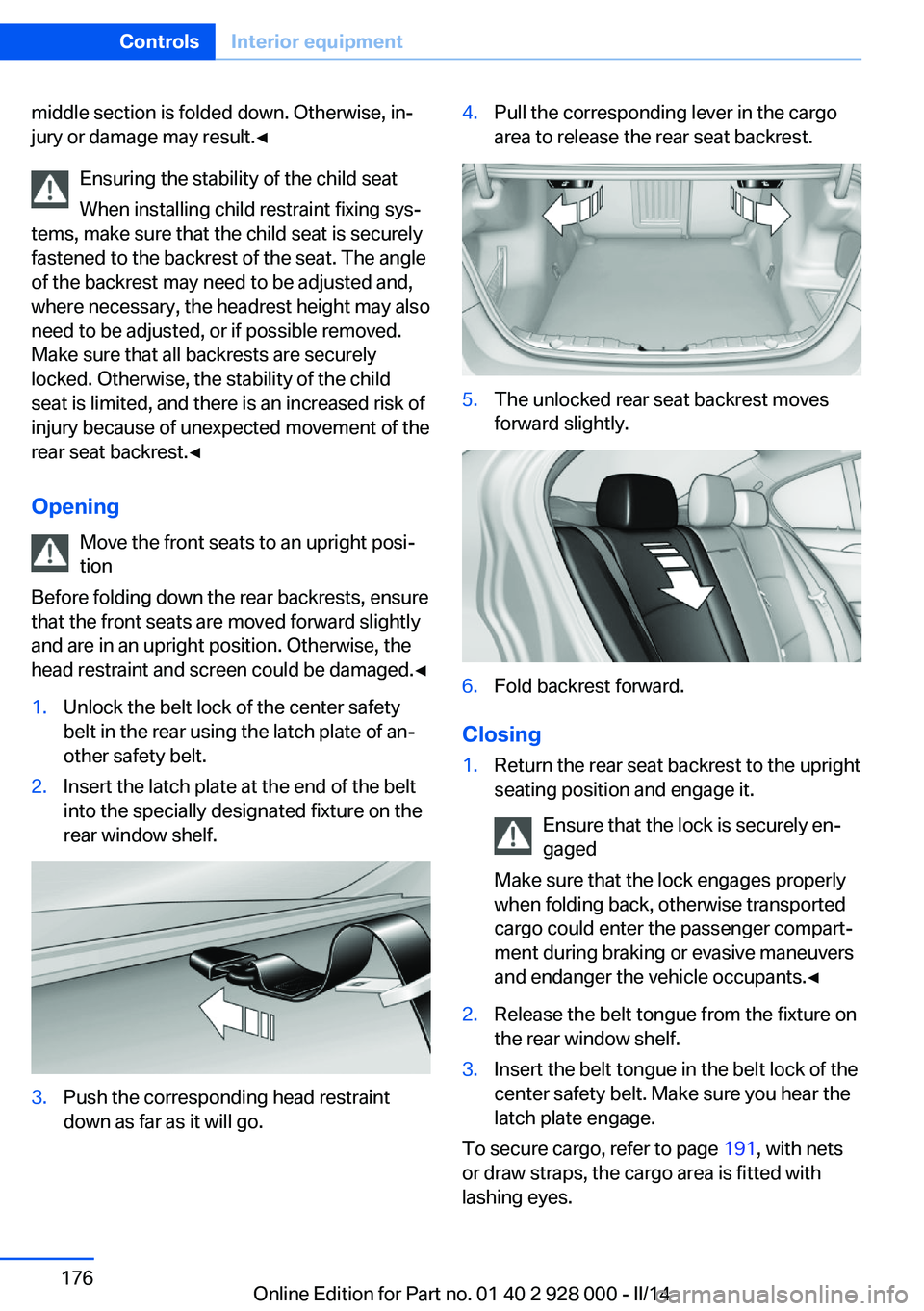
head restraint and screen could be damaged.◀1.Unlock the belt lock of the center safety
belt in the rear using the latch plate of an‐
other safety belt.2.Insert the latch plate at the end of the belt
into the specially designated fixture on the
rear window shelf.3.Push the corresponding head restraint
down as far as it will go.4.Pull the corresponding lever in the cargo
area to release the rear seat backrest.5.The unlocked rear seat backrest moves
forward slightly.6.Fold backrest forward.
Closing
1.Return the rear seat backrest to the upright
seating position and engage it.
Ensure that the lock is securely en‐
gaged
Make sure that the lock engages properly
when folding back, otherwise transported
cargo could enter the passenger compart‐
ment during braking or evasive maneuvers
and endanger the vehicle occupants.◀2.Release the belt tongue from the fixture on
the rear window shelf.3.Insert the belt tongue in the belt lock of the
center safety belt. Make sure you hear the
latch plate engage.
To secure cargo, refer to page 191, with nets
or draw straps, the cargo area is fitted with
lashing eyes.
Seite 176ControlsInterior equipment176
Online Edition for Part no. 01 40 2 928 000 - II/14
Page 187 of 267
Hot exhaust systemHot exhaust system
High temperatures are generated in the
exhaust system.
Do not remove the heat shields installed and
never apply undercoating to them. Make sure
that flammable materials, e. g. hay, leaves,
grass, etc. do not come in contact with the hot
exhaust system during driving, while in idle po‐
sition mode, or when parked. Such contact
could lead to a fire, and with it the risk of seri‐
ous personal injury as well as property dam‐
age.
Do not touch hot exhaust pipes; otherwise,
there is the danger of getting burned.◀
Diesel particulate filter The diesel particulate filter collects soot parti‐
cles and burns them periodically at high tem‐
peratures.
During the cleaning time of several minutes,
the following may occur:▷Temporarily, the engine may run less
smoothly.▷Noises and a slight amount of smoke com‐
ing from the exhaust until shortly after the
engine is shut down.▷A somewhat higher engine speed is neces‐
sary to achieve the accustomed perform‐
ance.
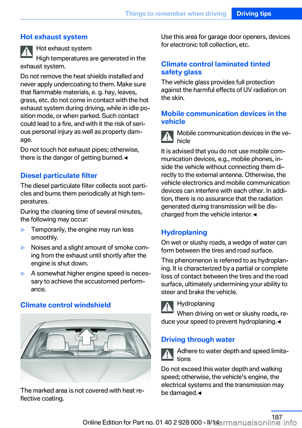
Climate control windshield
The marked area is not covered with heat re‐
flective coating.
Use this area for garage door openers, devices
for electronic toll collection, etc.
Climate control laminated tinted
safety glass
The vehicle glass provides full protection
against the harmful effects of UV radiation on
the skin.
Mobile communication devices in thevehicle
Mobile communication devices in the ve‐
hicle
It is advised that you do not use mobile com‐
munication devices, e.g., mobile phones, in‐
side the vehicle without connecting them di‐
rectly to the external antenna. Otherwise, the
vehicle electronics and mobile communication
devices can interfere with each other. In addi‐
tion, there is no assurance that the radiation
generated during transmission will be dis‐
charged from the vehicle interior.◀
Hydroplaning
On wet or slushy roads, a wedge of water can
form between the tires and road surface.
This phenomenon is referred to as hydroplan‐
ing. It is characterized by a partial or complete
loss of contact between the tires and the road
surface, ultimately undermining your ability to
steer and brake the vehicle.
Hydroplaning
When driving on wet or slushy roads, re‐
duce your speed to prevent hydroplaning.◀
Driving through water Adhere to water depth and speed limita‐
tions
Do not exceed this water depth and walking
speed; otherwise, the vehicle's engine, the
electrical systems and the transmission may
be damaged.◀Seite 187Things to remember when drivingDriving tips187
Online Edition for Part no. 01 40 2 928 000 - II/14
Page 222 of 267
Retreaded tires
Possibly substantial variations in the de‐
sign and age of the tire casing structures can
limit service life and have a negative impact on
road safety.◀
Winter tires
Winter tires are recommended for operating on
winter roads.
Although so-called all-season M+S tires do
provide better winter traction than summer tires, they do not provide the same level of per‐
formance as winter tires.
Maximum speed of winter tires If the maximum speed of the vehicle is higher
than the permissible speed for the winter tires,
then display a corresponding sign in the field
of vision. You can obtain this sign from the tire
specialist or from your service center.
Maximum speed for winter tires
Do not exceed the maximum speed for
the respective winter tires; otherwise, tire dam‐
age and accidents can occur.◀
Run-flat tires If you are already using run-flat tires, for your
own safety you should replace them only with
the same kind. No spare tire is available in the
case of a flat tire. Your service center will be
glad to advise you.
Rotating wheels between axles Different wear patterns can occur on the front
and rear axles depending on individual driving
conditions. The tires can be rotated between
the axles to achieve even wear. Your service
center will be glad to advise you. After rotating,
check the tire pressure and correct if neces‐
sary.
Rotating the tires is not permissible on vehi‐
cles with different tire sizes on the front andrear axles, i.e. when using different types of
tires.
Storage
Store wheels and tires in a cool, dry place with
as little exposure to light as possible.
Always protect tires against all contact with oil,
grease and fuels.
Do not exceed the maximum tire inflation pres‐
sure indicated on the side wall of the tire.
Run-flat tires
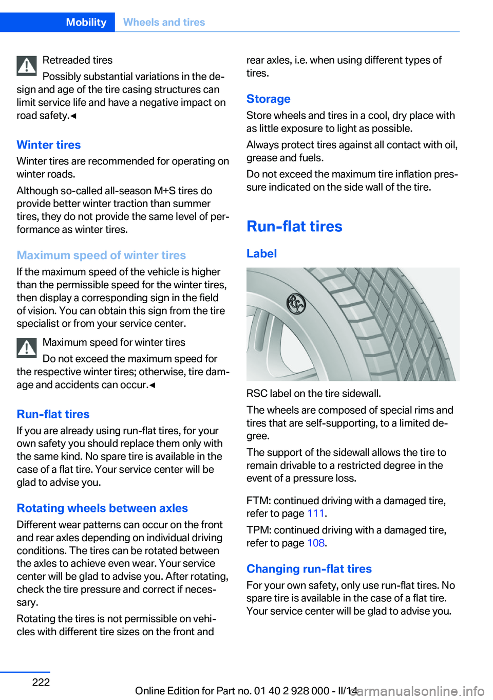
Label
RSC label on the tire sidewall.
The wheels are composed of special rims and
tires that are self-supporting, to a limited de‐
gree.
The support of the sidewall allows the tire to
remain drivable to a restricted degree in the
event of a pressure loss.
FTM: continued driving with a damaged tire,
refer to page 111.
TPM: continued driving with a damaged tire,
refer to page 108.
Changing run-flat tires
For your own safety, only use run-flat tires. No
spare tire is available in the case of a flat tire.
Your service center will be glad to advise you.
Seite 222MobilityWheels and tires222
Online Edition for Part no. 01 40 2 928 000 - II/14
Page 244 of 267
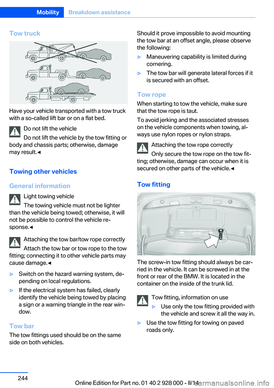
Tow truck
Have your vehicle transported with a tow truck
with a so-called lift bar or on a flat bed.
Do not lift the vehicle
Do not lift the vehicle by the tow fitting or
body and chassis parts; otherwise, damage
may result.◀
Towing other vehicles
General information Light towing vehicle
The towing vehicle must not be lighter
than the vehicle being towed; otherwise, it will
not be possible to control the vehicle re‐
sponse.◀
Attaching the tow bar/tow rope correctly
Attach the tow bar or tow rope to the tow
fitting; connecting it to other vehicle parts may
cause damage.◀
▷Switch on the hazard warning system, de‐
pending on local regulations.▷If the electrical system has failed, clearly
identify the vehicle being towed by placing
a sign or a warning triangle in the rear win‐
dow.
Tow bar
The tow fittings used should be on the same
side on both vehicles.
Should it prove impossible to avoid mounting
the tow bar at an offset angle, please observe
the following:▷Maneuvering capability is limited during
cornering.▷The tow bar will generate lateral forces if it
is secured with an offset.
Tow rope
When starting to tow the vehicle, make sure
that the tow rope is taut.
To avoid jerking and the associated stresses
on the vehicle components when towing, al‐
ways use nylon ropes or nylon straps.
Attaching the tow rope correctly
Only secure the tow rope on the tow fit‐
ting; otherwise, damage can occur when it is
secured on other parts of the vehicle.◀
Tow fitting
The screw-in tow fitting should always be car‐
ried in the vehicle. It can be screwed in at the
front or rear of the BMW. It is located in the
container on the inside of the trunk lid.
Tow fitting, information on use
▷Use only the tow fitting provided with
the vehicle and screw it all the way in.▷Use the tow fitting for towing on paved
roads only.Seite 244MobilityBreakdown assistance244
Online Edition for Part no. 01 40 2 928 000 - II/14
Page 263 of 267
Roller sunblinds 44
Roll stabilization, refer to Adaptive Drive 132
Roll stabilization, refer to Dy‐ namic Drive 132
RON recommended fuel grade 204
Roof load capacity 252
Roof-mounted luggage rack 191
Rope for tow-starting/ towing 244
RSC Run Flat System Com‐ ponent, refer to Run-flat
tires 222
Rubber components, care 248
Run-flat tires 222
S Safe braking 188
Safety 7
Safety belt reminder for driv‐ er's seat and front passen‐
ger seat 52
Safety belts 51
Safety belts, care 248
Safety Package, refer to Ac‐ tive Protection 126
Safety switch, windows 44
Safety systems, airbags 103
Saving fuel 193
Screen, refer to Control Dis‐ play 16
Screwdriver, see Onboard ve‐ hicle tool kit 233
Screw thread for tow fit‐ ting 245
Seat belts, refer to Safety belts 51
Seat heating, front 50
Seat heating, rear 50
Seating position for chil‐ dren 59 Seat, mirror, and steering
wheel memory 54
Seats 47
Seat ventilation, front 51
Selection list in instrument cluster 91
Selector lever, automatic transmission 74
Sensors, care 249
Service and warranty 8
Service requirements, Condi‐ tion Based Service
CBS 231
Service requirements, dis‐ play 88
Service, Roadside Assis‐ tance 241
Services, ConnectedDrive
Settings, locking/unlock‐ ing 41
Settings on Control Dis‐ play 94
Settings, storing for seat, mir‐ rors, steering wheel 54
Shifting, automatic transmis‐ sion 74
Shifting, manual transmis‐ sion 73
Shift Lights 84
Shift paddles on steering wheel 76
Shoulder support 50
Side airbags 103
Side View 154
Signaling, horn 12
Signals when unlocking 41
Sitting safely 47
Size 252
Ski bag 177
Slide/tilt glass roof 45
Smallest turning circle 252
Smoker's package 172
Snow chains 223
Socket 174
Socket, OBD Onboard Diag‐ nostics 231 Soot particulate filter 187
SOS button 240
Spare fuse 239
Speaker lighting 102
Specified engine oil types 228
Speed, average 93
Speed limit detection, on‐ board computer 93
Speed limiter, display 90
Speed Limit Information 90
Speed warning 94
Split screen 21
SPORT+ - program, Dynamic Driving Control 134
Sport automatic transmis‐ sion 76
Sport displays, torque dis‐ play, performance dis‐
play 94
SPORT program, driving dy‐ namics 134
Sport program, transmis‐ sion 75
Stability control systems 129
Start/stop, automatic func‐ tion 65
Start/Stop button 63
Start function during malfunc‐ tion 31
Starting the engine 64
Status control display, tires 106
Status information, iDrive 20
Status of Owner's Manual 6
Steering, Integral Active Steering 133
Steering wheel, adjusting 57
Steering wheel heating 58
Steering wheel memory 54
Steptronic, automatic trans‐ mission 74
Stopping the engine 65
Storage compartment, re‐ mote control 182
Storage compartments 179 Seite 263Everything from A to ZReference263
Online Edition for Part no. 01 40 2 928 000 - II/14