trunk BMW 535I 2011 F10 User Guide
[x] Cancel search | Manufacturer: BMW, Model Year: 2011, Model line: 535I, Model: BMW 535I 2011 F10Pages: 304, PDF Size: 10.18 MB
Page 51 of 304
Before transporting passengers
Reinstall the head restraint before trans‚Äê
porting anyone in the seat; otherwise, the pro‚Äê
tective function of the head restraint is unavail‚Äê
able.‚óÄ
Seat, mirror, and steering
wheel memory*
General information
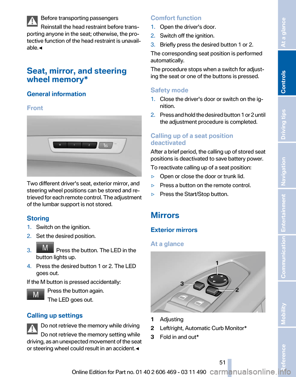
Front Two different driver's seat, exterior mirror, and
steering wheel positions can be stored and re‚Äê
trieved
for each remote control. The adjustment
of the lumbar support is not stored.
Storing
1. Switch on the ignition.
2. Set the desired position.
3. Press the button. The LED in the
button lights up.
4. Press the desired button 1 or 2. The LED
goes out.
If the M button is pressed accidentally: Press the button again.
The LED goes out.
Calling up settings Do not retrieve the memory while driving
Do not retrieve the memory setting while
driving,
as an unexpected movement of the seat
or steering wheel could result in an accident.‚óÄ Comfort function
1.
Open the driver's door.
2. Switch off the ignition.
3. Briefly press the desired button 1 or 2.
The corresponding seat position is performed
automatically.
The procedure stops when a switch for adjust‚Äê
ing the seat or one of the buttons is pressed.
Safety mode
1. Close the driver's door or switch on the ig‚Äê
nition.
2. Press and hold the desired button 1 or 2 until
the adjustment procedure is completed.
Calling up of a seat position
deactivated
After
a brief period, the calling up of stored seat
positions is deactivated to save battery power.
To reactivate calling up of a seat position:
‚ñ∑ Open or close the door or trunk lid.
‚ñ∑ Press a button on the remote control.
‚ñ∑ Press the Start/Stop button.
Mirrors
Exterior mirrors
At a glance 1
Adjusting
2 Left/right, Automatic Curb Monitor*
3 Fold in and out*
Seite 51
51Online Edition for Part no. 01 40 2 606 469 - 03 11 490
Reference Mobility Communication Entertainment Navigation Driving tips
Controls At a glance
Page 114 of 304
Detection of objects
High, protruding objects such as ledges
may not be detected by the backup camera.
‚óÄ
Switching on automatically
Select transmission position R with the engine
running.
The backup camera image is displayed if the
system was switched on via the iDrive.
Switching off automatically
The system switches off and the LED goes out:
‚ñ∑ After approx. 33 ft/10 m when driving for‚Äê
ward.
‚ñ∑ Above approx. 9 mph/15 km/h when driving
forward.
Switch on the system again if necessary.
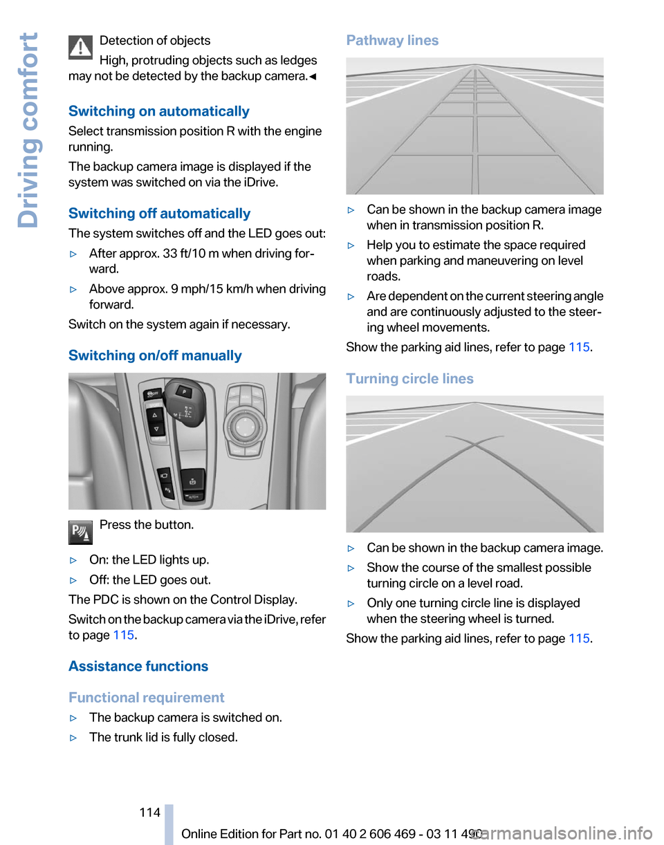
Switching on/off manually Press the button.
‚ñ∑ On: the LED lights up.
‚ñ∑ Off: the LED goes out.
The PDC is shown on the Control Display.
Switch
on the backup camera via the iDrive, refer
to page 115.
Assistance functions
Functional requirement
‚ñ∑ The backup camera is switched on.
‚ñ∑ The trunk lid is fully closed. Pathway lines
‚ñ∑
Can be shown in the backup camera image
when in transmission position R.
‚ñ∑ Help you to estimate the space required
when parking and maneuvering on level
roads.
‚ñ∑ Are dependent on the current steering angle
and are continuously adjusted to the steer‚Äê
ing wheel movements.
Show the parking aid lines, refer to page 115.
Turning circle lines ‚ñ∑
Can be shown in the backup camera image.
‚ñ∑ Show the course of the smallest possible
turning circle on a level road.
‚ñ∑ Only one turning circle line is displayed
when the steering wheel is turned.
Show the parking aid lines, refer to page 115.
Seite 114
114 Online Edition for Part no. 01 40 2 606 469 - 03 11 490
Driving comfort
Page 116 of 304
Camera
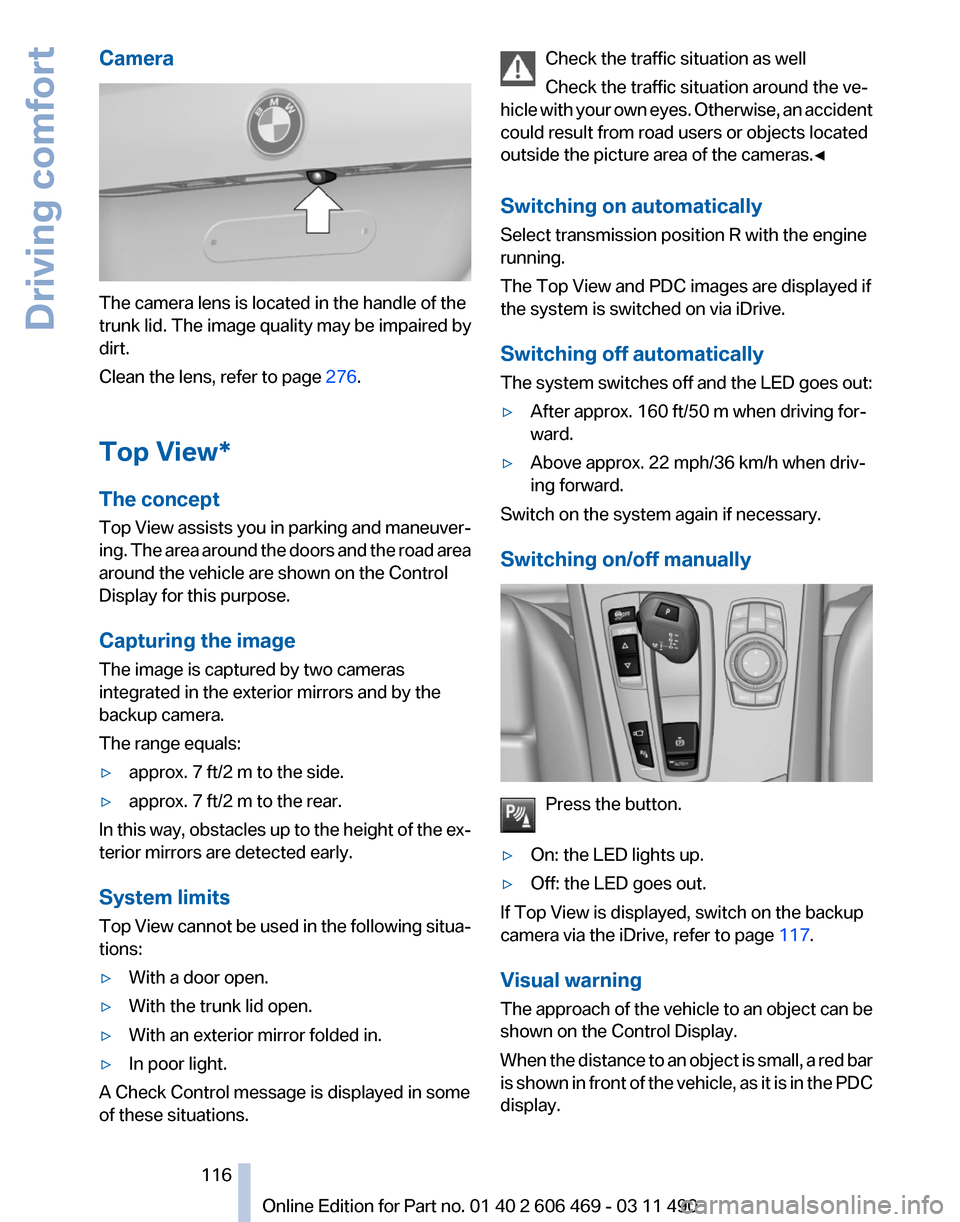
The camera lens is located in the handle of the
trunk lid. The image quality may be impaired by
dirt.
Clean the lens, refer to page
276.
Top View*
The concept
Top
View assists you in parking and maneuver‚Äê
ing. The area around the doors and the road area
around the vehicle are shown on the Control
Display for this purpose.
Capturing the image
The image is captured by two cameras
integrated in the exterior mirrors and by the
backup camera.
The range equals:
‚ñ∑ approx. 7 ft/2 m to the side.
‚ñ∑ approx. 7 ft/2 m to the rear.
In this way, obstacles up to the height of the ex‚Äê
terior mirrors are detected early.
System limits
Top
View cannot be used in the following situa‚Äê
tions:
‚ñ∑ With a door open.
‚ñ∑ With the trunk lid open.
‚ñ∑ With an exterior mirror folded in.
‚ñ∑ In poor light.
A Check Control message is displayed in some
of these situations. Check the traffic situation as well
Check the traffic situation around the ve‚Äê
hicle
with your own eyes. Otherwise, an accident
could result from road users or objects located
outside the picture area of the cameras.‚óÄ
Switching on automatically
Select transmission position R with the engine
running.
The Top View and PDC images are displayed if
the system is switched on via iDrive.
Switching off automatically
The system switches off and the LED goes out:
‚ñ∑ After approx. 160 ft/50 m when driving for‚Äê
ward.
‚ñ∑ Above approx. 22 mph/36 km/h when driv‚Äê
ing forward.
Switch on the system again if necessary.
Switching on/off manually Press the button.
‚ñ∑ On: the LED lights up.
‚ñ∑ Off: the LED goes out.
If Top View is displayed, switch on the backup
camera via the iDrive, refer to page 117.
Visual warning
The
approach of the vehicle to an object can be
shown on the Control Display.
When the distance to an object is small, a red bar
is shown in front of the vehicle, as it is in the PDC
display. Seite 116
116 Online Edition for Part no. 01 40 2 606 469 - 03 11 490
Driving comfort
Page 139 of 304
Close the glove compartment again im‚Äê
mediately
Close
the glove compartment immediately after
use while driving; otherwise, injury may occur
during accidents.‚óÄ
Closing
Fold up the cover.
Center armrest
Front
A storage compartment is located in the center
armrest between the front seats.
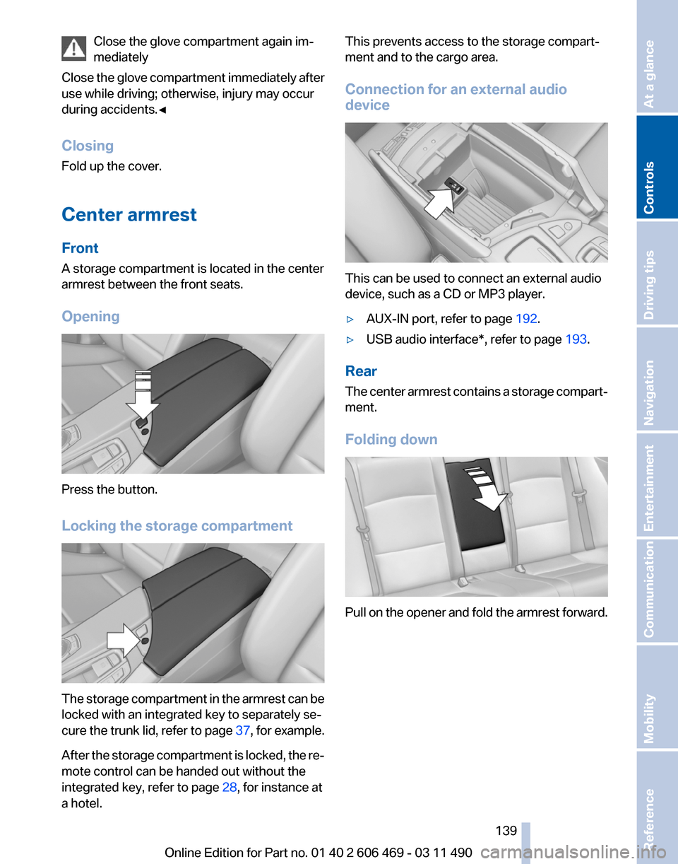
Opening Press the button.
Locking the storage compartment
The storage compartment in the armrest can be
locked with an integrated key to separately se‚Äê
cure
the trunk lid, refer to page 37, for example.
After the storage compartment is locked, the re‚Äê
mote control can be handed out without the
integrated key, refer to page 28, for instance at
a hotel. This prevents access to the storage compart‚Äê
ment and to the cargo area.
Connection for an external audio
device
This can be used to connect an external audio
device, such as a CD or MP3 player.
‚ñ∑
AUX-IN port, refer to page 192.
‚ñ∑ USB audio interface*, refer to page 193.
Rear
The
center armrest contains a storage compart‚Äê
ment.
Folding down Pull on the opener and fold the armrest forward.
Seite 139
139Online Edition for Part no. 01 40 2 606 469 - 03 11 490
Reference Mobility Communication Entertainment Navigation Driving tips
Controls At a glance
Page 142 of 304
Light and suitable objects only
Only hang light bags or suitable objects
from
the holders. Otherwise, there is a danger of
objects flying about during braking and evasive
maneuvers.
Only transport heavy luggage in the trunk if it has
been appropriately secured.‚óÄ
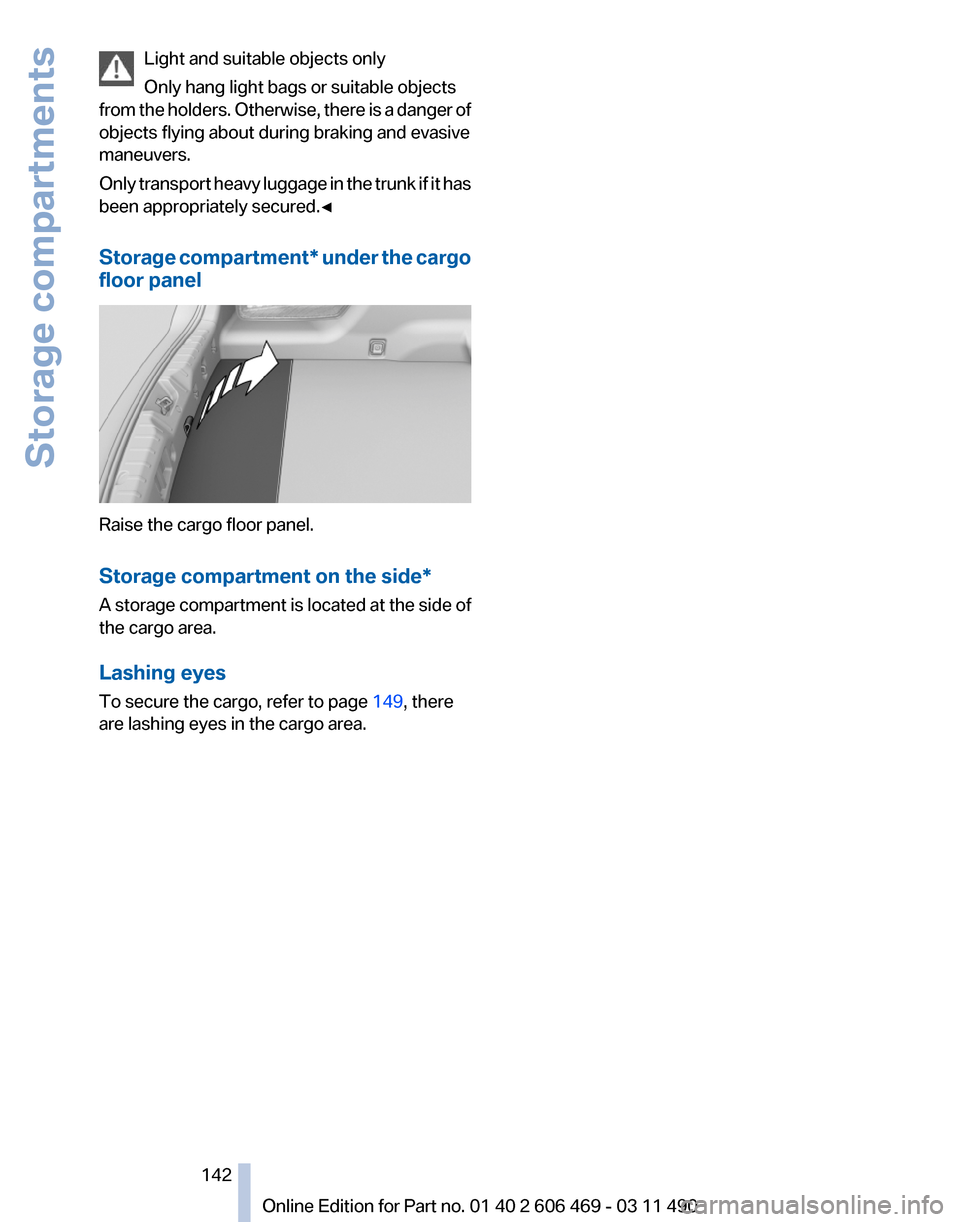
Storage compartment* under the cargo
floor panel Raise the cargo floor panel.
Storage compartment on the side
*
A storage compartment is located at the side of
the cargo area.
Lashing eyes
To secure the cargo, refer to page 149, there
are lashing eyes in the cargo area. Seite 142
142 Online Edition for Part no. 01 40 2 606 469 - 03 11 490
Storage compartments
Page 146 of 304
Things to remember when driving
Breaking-in period
General information
Moving parts need to be broken in to adjust to
each other.
The following instructions will help achieve a
long vehicle life and good economy.
Engine and differential
Always obey the official speed limit.
Up to 1,200 miles/2,000 km
Do not exceed the maximum engine and road
speed:
‚ñ∑
For gasoline engine, 4500 rpm and
100 mph/160 km/h.
Avoid full-throttle operation and use of the
transmission's kickdown mode for the initial
miles.
From 1,200 miles/2,000 km
The engine and vehicle speed can gradually be
increased.
Tires
Due to technical factors associated with their
manufacture,
tires do not achieve their full trac‚Äê
tion potential until after an initial breaking-in pe‚Äê
riod.
Drive conservatively for the first 200 miles/
300 km.
Brake system
Brakes require an initial break-in period of ap‚Äê
prox. 300 miles/500 km to achieve optimized
contact and wear patterns between brake pads
and discs. Drive moderately during this break-in
period.
Clutch
The function of the clutch reaches its optimal
level only after a distance driven of approx. 300 miles/500 km. During this break-in period,
engage the clutch gently.
Following part replacement
The
same breaking in procedures should be ob‚Äê
served if any of the components mentioned
above have to be renewed in the course of the
vehicle's operating life.
General driving notes
Closing the trunk lid
Drive with the trunk lid closed
Only drive with the tailgate closed; other‚Äê
wise, in the event of an accident or braking or
evasive maneuvers, passengers or other road
users may be injured or the vehicle may be dam‚Äê
aged. In addition, exhaust fumes may enter the
passenger compartment.‚óÄ
If driving with the tailgate open cannot be
avoided:
‚ñ∑ Close all windows and the glass sunroof*.
‚ñ∑ Greatly increase the blower speed.
‚ñ∑ Drive moderately.
Hot exhaust system Hot exhaust system
High temperatures are generated in the
exhaust system.
Do not remove the heat shields installed and
never apply undercoating to them. When driv‚Äê
ing,
standing at idle and while parking, take care
to avoid possible contact between the hot ex‚Äê
haust system and any highly flammable materi‚Äê
als such as hay, leaves, grass, etc. Such contact
could lead to a fire, and with it the risk of serious
personal injury as well as property damage.
Do not touch hot exhaust pipes; otherwise, there
is the danger of getting burned.‚óÄ Seite 146
146 Online Edition for Part no. 01 40 2 606 469 - 03 11 490
Things to remember when driving
Page 148 of 304
Driving in wet conditions
When
roads are wet or there is heavy rain, briefly
exert gentle pressure on the brake pedal every
few miles.
Ensure that this action does not endanger other
road users.
The heat generated in this process helps dry the
brake discs and pads.
In this way braking efficiency will be available
when you need it.
Hills
Drive long or steep downhill gradients in the gear
in which the least braking is required. Otherwise,
the brake system may overheat, resulting in a
reduction in the brake system efficiency.
Manual transmission:
You can increase the engine's braking effect by
shifting down, going all the way to first gear, if
necessary.
Automatic transmission*:
You can increase the engine's braking effect by
shifting down in the manual mode of the auto‚Äê
matic transmission, refer to page 65.
Avoid load on the brakes
Avoid placing excessive load on the brake
system. Light but consistent brake pressure can
lead to high temperatures, brake wear and pos‚Äê
sibly even brake failure.‚óÄ
Do not drive in neutral
Do not drive in neutral or with the engine
stopped, as doing so disables engine braking. In
addition, steering and brake assist is unavailable
with the engine stopped.‚óÄ
Brake disc corrosion
Corrosion on the brake discs and contamination
on the brake pads are furthered by:
‚ñ∑ Low mileage.
‚ñ∑ Extended periods when the vehicle is not
used at all.
‚ñ∑ Infrequent use of the brakes. Corrosion occurs when the minimum pressure
that must be exerted by the pads during brake
applications to clean the discs is not reached.
Should corrosion form on the brake discs, the
brakes will tend to respond with a pulsating ef‚Äê
fect that generally cannot be corrected.
Condensation
under the parked vehicle
When using the automatic climate control, con‚Äê
densation water develops that exits underneath
the vehicle.
Therefore, traces of condensed water under the
vehicle are normal.
Loading
Overloading the vehicle
To avoid exceeding the approved carrying
capacity of the tires, never overload the vehicle.
Overloading can lead to overheating and in‚Äê
creases the rate at which damage develops in‚Äê
side the tires. This could result in a sudden loss
of tire inflation pressure.‚óÄ
No fluids in the trunk
Make sure that fluids do not leak into the
trunk; otherwise, the vehicle may be damaged.‚óÄ
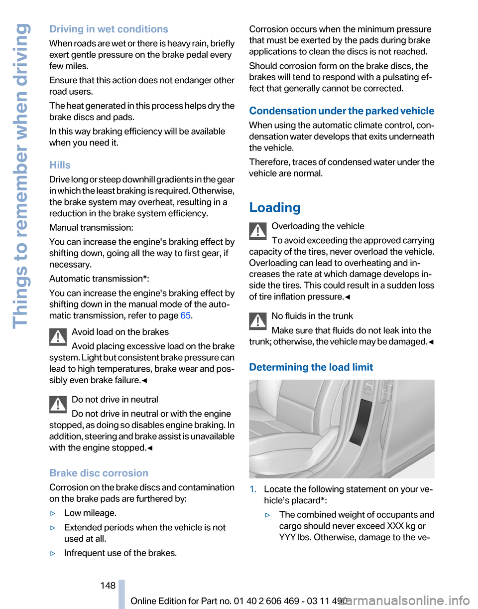
Determining the load limit 1.
Locate the following statement on your ve‚Äê
hicle’s placard*:
‚ñ∑The combined weight of occupants and
cargo should never exceed XXX kg or
YYY lbs. Otherwise, damage to the ve‚Äê Seite 148
148 Online Edition for Part no. 01 40 2 606 469 - 03 11 490
Things to remember when driving
Page 150 of 304
Securing cargo
Always position and secure the cargo as
described
above; otherwise, it can endanger the
car's occupants if sudden braking or swerving
becomes necessary.
Heavy or hard objects should not be carried
loose inside the car; otherwise, they could be
thrown around as a result of hard braking, sud‚Äê
den swerves, etc., and endanger the occu‚Äê
pants.‚óÄ
Roof-mounted luggage rack
Note
Roof racks are available as special accessories.
Attachment
Follow the installation instructions of the roof
rack.
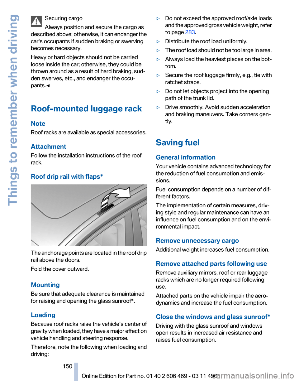
Roof drip rail with flaps* The anchorage points are located in the roof drip
rail above the doors.
Fold the cover outward.
Mounting
Be sure that adequate clearance is maintained
for raising and opening the
glass sunroof*.
Loading
Because roof racks raise the vehicle's center of
gravity when loaded, they have a major effect on
vehicle handling and steering response.
Therefore, note the following when loading and
driving: ‚ñ∑
Do not exceed the approved roof/axle loads
and
the approved gross vehicle weight, refer
to page 283.
‚ñ∑ Distribute the roof load uniformly.
‚ñ∑ The roof load should not be too large in area.
‚ñ∑ Always load the heaviest pieces on the bot‚Äê
tom.
‚ñ∑ Secure the roof luggage firmly, e.g., tie with
ratchet straps.
‚ñ∑ Do not let objects project into the opening
path of the trunk lid.
‚ñ∑ Drive smoothly. Avoid sudden acceleration
and braking maneuvers. Take corners gen‚Äê
tly.
Saving fuel
General information
Your vehicle contains advanced technology for
the reduction of fuel consumption and emis‚Äê
sions.
Fuel consumption depends on a number of dif‚Äê
ferent factors.
The implementation of certain measures, driv‚Äê
ing style and regular maintenance can have an
influence on fuel consumption and on the envi‚Äê
ronmental impact.
Remove unnecessary cargo
Additional weight increases fuel consumption.
Remove attached parts following use
Remove auxiliary mirrors, roof or rear luggage
racks which are no longer required following
use.
Attached parts on the vehicle impair the aero‚Äê
dynamics and increase the fuel consumption.
Close the windows and glass sunroof
*
Driving with the glass sunroof and windows
open results in increased air resistance and
raises fuel consumption.
Seite 150
150 Online Edition for Part no. 01 40 2 606 469 - 03 11 490
Things to remember when driving
Page 262 of 304
Replacing components
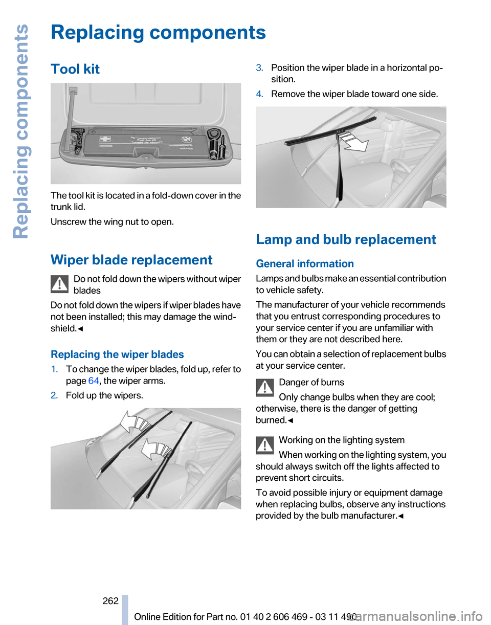
Tool kit
The tool kit is located in a fold-down cover in the
trunk lid.
Unscrew the wing nut to open.
Wiper blade replacement
Do
not fold down the wipers without wiper
blades
Do not fold down the wipers if wiper blades have
not been installed; this may damage the wind‚Äê
shield.‚óÄ
Replacing the wiper blades
1. To change the wiper blades, fold up, refer to
page 64, the wiper arms.
2. Fold up the wipers. 3.
Position the wiper blade in a horizontal po‚Äê
sition.
4. Remove the wiper blade toward one side. Lamp and bulb replacement
General information
Lamps
and bulbs make an essential contribution
to vehicle safety.
The manufacturer of your vehicle recommends
that you entrust corresponding procedures to
your service center if you are unfamiliar with
them or they are not described here.
You can obtain a selection of replacement bulbs
at your service center.
Danger of burns
Only change bulbs when they are cool;
otherwise, there is the danger of getting
burned.‚óÄ
Working on the lighting system
When working on the lighting system, you
should always switch off the lights affected to
prevent short circuits.
To avoid possible injury or equipment damage
when replacing bulbs, observe any instructions
provided by the bulb manufacturer.‚óÄ Seite 262
262 Online Edition for Part no. 01 40 2 606 469 - 03 11 490Replacing components
Page 266 of 304
Turn signal, outer brake, tail, and
license plate lamps
Follow the general instructions on lamps and
bulbs, refer to page
262.
These lights are made using LED technology.
Contact your service center in the event of a
malfunction.
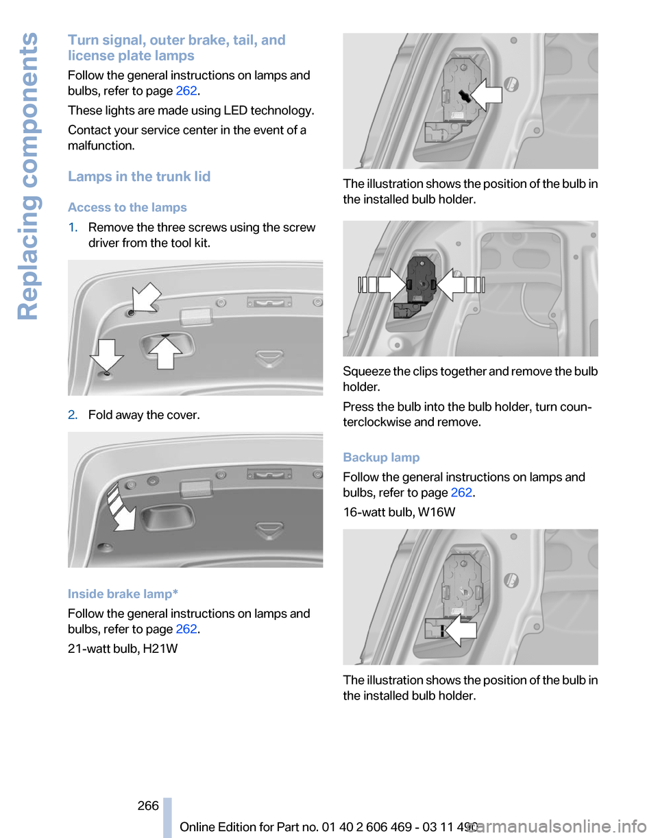
Lamps in the trunk lid
Access to the lamps
1. Remove the three screws using the screw
driver from the tool kit. 2.
Fold away the cover. Inside brake lamp*
Follow the general instructions on lamps and
bulbs, refer to page
262.
21-watt bulb, H21W The illustration shows the position of the bulb in
the installed bulb holder.
Squeeze the clips together and remove the bulb
holder.
Press the bulb into the bulb holder, turn coun‚Äê
terclockwise and remove.
Backup lamp
Follow the general instructions on lamps and
bulbs, refer to page
262.
16-watt bulb, W16W The illustration shows the position of the bulb in
the installed bulb holder.
Seite 266
266 Online Edition for Part no. 01 40 2 606 469 - 03 11 490Replacing components