WHEELS BMW 535I 2011 F10 Owner's Manual
[x] Cancel search | Manufacturer: BMW, Model Year: 2011, Model line: 535I, Model: BMW 535I 2011 F10Pages: 304, PDF Size: 10.18 MB
Page 5 of 304
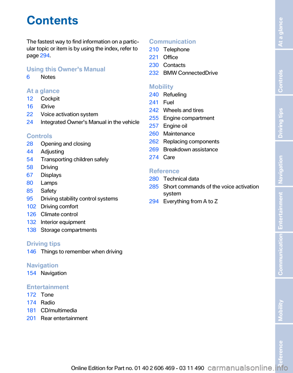
Contents
The fastest way to find information on a partic‐
ular topic or item is by using the index, refer to
page
294.
Using this Owner's Manual
6 Notes
At a glance
12 Cockpit
16 iDrive
22 Voice activation system
24 Integrated Owner's Manual in the vehicle
Controls
28 Opening and closing
44 Adjusting
54 Transporting children safely
58 Driving
67 Displays
80 Lamps
85 Safety
95 Driving stability control systems
102 Driving comfort
126 Climate control
132 Interior equipment
138 Storage compartments
Driving tips
146 Things to remember when driving
Navigation
154 Navigation
Entertainment
172 Tone
174 Radio
181 CD/multimedia
201 Rear entertainment Communication
210
Telephone
221 Office
230 Contacts
232 BMW ConnectedDrive
Mobility
240 Refueling
241 Fuel
242 Wheels and tires
255 Engine compartment
257 Engine oil
260 Maintenance
262 Replacing components
269 Breakdown assistance
274 Care
Reference
280 Technical data
285 Short commands of the voice activation
system
294 Everything from A to Z
Seite 5
Online Edition for Part no. 01 40 2 606 469 - 03 11 490 Reference Mobility Communication Entertainment Navigation Driving tips Controls At a glance
Page 7 of 304
For your own safety
Maintenance and repairs
Advanced technology, e.g., the use of modern
materials
and high-performance electronics, re‐
quires suitable maintenance and repair meth‐
ods.
Therefore, have this work performed only by a
BMW center or a workshop that works accord‐
ing to BMW repair procedures with appropri‐
ately trained personnel.
If this work is not carried out properly, there is
the danger of subsequent damage and related
safety hazards.
Parts and Accessories
For your own safety, use genuine parts and ac‐
cessories approved by BMW. When you pur‐
chase accessories tested and approved by
BMW and Genuine BMW Parts, you simultane‐
ously acquire the assurance that they have been
thoroughly tested by BMW to ensure optimum
performance when installed on your vehicle.
BMW warrants these parts to be free from de‐
fects in material and workmanship. BMW will not
accept any liability for damage resulting from in‐
stallation of parts and accessories not approved
by BMW. BMW cannot test every product made
by other manufacturers to verify if it can be used
on a BMW safely and without risk to either the
vehicle, its operation, or its occupants. Genuine
BMW Parts, BMW Accessories and other prod‐
ucts approved by BMW, together with profes‐
sional advice on using these items, are available
from all BMW centers. Installation and operation
of non-BMW approved accessories such as
alarms, radios, amplifiers, radar detectors,
wheels, suspension components, brake dust
shields, telephones, including operation of any
mobile phone from within the vehicle without
using an externally mounted antenna, or trans‐
ceiver equipment, for instance, CBs, walkie-
talkies, ham radios or similar accessories, may
cause extensive damage to the vehicle, com‐
promise its safety, interfere with the vehicle's
electrical system or affect the validity of the
BMW Limited Warranty. See your BMW center for additional information. Maintenance, re‐
placement,
or repair of the emission control de‐
vices and systems may be performed by any au‐
tomotive repair establishment or individual
using any certified automotive part.
California Proposition 65 Warning
California laws require us to state the following
warning:
Engine exhaust and a wide variety of automobile
components and parts, including components
found in the interior furnishings in a vehicle, con‐
tain or emit chemicals known to the State of Cal‐
ifornia to cause cancer and birth defects and re‐
productive harm. In addition, certain fluids
contained in vehicles and certain products of
component wear contain or emit chemicals
known to the State of California to cause cancer
and birth defects or other reproductive harm.
Battery posts, terminals and related accessories
contain lead and lead compounds. Wash your
hands after handling. Used engine oil contains
chemicals that have caused cancer in laboratory
animals. Always protect your skin by washing
thoroughly with soap and water.
Service and warranty
We recommend that you read this publication
thoroughly. Your vehicle is covered by the fol‐
lowing warranties:
▷ New Vehicle Limited Warranty.
▷ Rust Perforation Limited Warranty.
▷ Federal Emissions System Defect Warranty.
▷ Federal Emissions Performance Warranty.
▷ California Emission Control System Limited
Warranty.
Detailed information about these warranties is
listed in the Service and Warranty Information
Booklet for US models or in the Warranty and
Service Guide Booklet for Canadian models.
Your vehicle has been specifically adapted and
designed to meet the particular operating con‐
ditions and homologation requirements in your
country
and continental region in order to deliver
the full driving pleasure while the vehicle is op‐
erated under those conditions. If you wish to op‐
Seite 7
7Online Edition for Part no. 01 40 2 606 469 - 03 11 490
Reference Mobility Communication Entertainment Navigation Driving tips Controls At a glance
Page 60 of 304
Parking brake
The concept
The parking brake is primarily intended to pre‐
vent the vehicle from rolling while parked; it
brakes the rear wheels.
In cars with automatic transmission*:
The parking brake can be set manually or auto‐
matically:
▷
Manual: by pulling and pushing the switch.
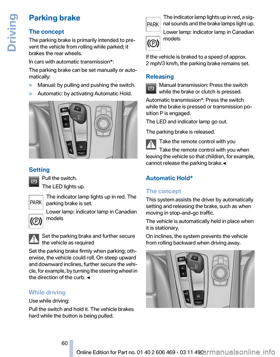
▷ Automatic: by activating Automatic Hold. Setting
Pull the switch.
The LED lights up.
The indicator lamp lights up in red. The
parking brake is set.
Lower lamp: indicator lamp in Canadian
models
Set the parking brake and further secure
the vehicle as required
Set the parking brake firmly when parking; oth‐
erwise, the vehicle could roll. On steep upward
and
downward inclines, further secure the vehi‐
cle, for example, by turning the steering wheel in
the direction of the curb. ◀
While driving
Use while driving:
Pull the switch and hold it. The vehicle brakes
hard while the button is being pulled. The indicator lamp lights up in red, a sig‐
nal
sounds and the brake lamps light up.
Lower lamp: indicator lamp in Canadian
models
If the vehicle is braked to a speed of approx.
2 mph/3 km/h, the parking brake remains set.
Releasing Manual transmission: Press the switch
while the brake or clutch is pressed.
Automatic transmission*: Press the switch
while the brake is pressed or transmission po‐
sition P is engaged.
The LED and indicator lamp go out.
The parking brake is released.
Take the remote control with you
Take the remote control with you when
leaving the vehicle so that children, for example,
cannot release the parking brake.◀
Automatic Hold*
The concept
This system assists the driver by automatically
setting and releasing the brake, such as when
moving in stop-and-go traffic.
The vehicle is automatically held in place when
it is stationary.
On inclines, the system prevents the vehicle
from rolling backward when driving away. Seite 60
60 Online Edition for Part no. 01 40 2 606 469 - 03 11 490
Driving
Page 65 of 304
Automatic transmission with
Steptronic*
Transmission positions
D Drive, automatic position
Position for normal vehicle operation. All for‐
ward gears are available.
R is Reverse
Select only when the vehicle is stationary.
N is Neutral
Use in automatic car washes, for example. The
vehicle can roll.
When the ignition is switched off, refer to
page
58, position P is engaged automatically.
P Park
Select only when the vehicle is stationary. The
drive wheels are blocked.
P is engaged automatically:
▷ After the engine is switched off, if the car is
in
radio ready state, refer to page 58, or if the
ignition is switched off, refer to page 58, and
if position R or D is engaged.
▷ If the ignition is switched off and position N
is engaged.
▷ If the safety belt is unbuckled, the driver's
door is opened, and the brake pedal is not
pressed while the vehicle is stationary and
transmission position R or D is engaged.
Kickdown
Kickdown is used to achieve maximum driving
performance. Press on the accelerator beyond
the resistance point at the full throttle position.
Engaging the transmission position
▷ Transmission position P can only be disen‐
gaged
if the engine is running and the brake
pedal is pressed.
▷ With the vehicle stationary, press on the
brake pedal before shifting out of P or N; otherwise, the shift command will not be
executed: shift lock.
Depress
the brake until you start driv‐
ing
To prevent the vehicle from creeping after
you select a driving position, maintain pres‐
sure on the brake pedal until you are ready
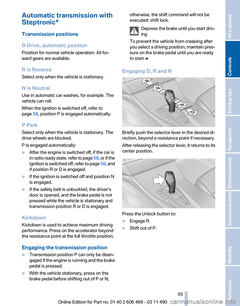
to start.◀ Engaging D, R and N
Briefly push the selector lever in the desired di‐
rection, beyond a resistance point if necessary.
After
releasing the selector lever, it returns to its
center position. Press the Unlock button to:
▷
Engage R.
▷ Shift out of P.
Seite 65
65Online Edition for Part no. 01 40 2 606 469 - 03 11 490
Reference Mobility Communication Entertainment Navigation Driving tips
Controls At a glance
Page 88 of 304
If the message does not disappear after a repeat
calibration,
have the system checked as soon as
possible.
Unobstructed area of movement
Ensure that the area of movement of the
seats is unobstructed to avoid personal injury or
damage to objects.◀
Tire Pressure Monitor TPM*
The concept
The tire inflation pressure is measured in the
four mounted tires. The system notifies you if
there is a significant loss of pressure in one or
more tires.
Functional requirements
The system must have been reset when the in‐
flation pressure was correct; otherwise, reliable
signaling of a flat tire is not ensured. Always use
wheels with TPM electronics to ensure that the
system will operate properly. Reset the system
after each correction of the tire inflation pres‐
sure and after every tire or wheel change.
System limits
Sudden tire damage
Sudden serious tire damage caused by
external influences cannot be indicated in ad‐
vance.◀
The system does not operate correctly if it has
not been reset. For example, a flat tire may be
indicated despite correct tire inflation pres‐
sures.
The system is inactive and cannot indicate a flat
tire:
▷ For a mounted wheel without TPM electron‐
ics.
▷ When the TPM is disturbed by other sys‐
tems or devices with the same radio fre‐
quency. Status display
The
current status of the Tire Pressure Monitor
TPM can be displayed on the Control Display,
e.g., whether or not the TPM is active.
1. "Vehicle Info"
2. "Vehicle status"
3. "Tire Pressure Monitor - TPM"
The status is displayed.
Status display
The tire and system status is indicated by the
color of the tires.
A change in the tire inflation pressure during
driving is taken into account.
A
correction is only necessary if this is indicated
by the TPM
Wheels, green
The tire inflation pressure is equal to the target
state.
One wheel is yellow
A flat tire or major drop in inflation pressure in
the indicated tire.
All wheels are yellow
▷ A flat tire or major drop in inflation pressure
in several tires.
▷ The system was not reset after a wheel
change and thus warns based on the infla‐
tion pressures initialized last.
▷ A flat tire in one or more tires while the sys‐
tem is being reset.
Wheels, gray
The
system cannot detect a flat tire. Reasons for
this may be:
▷ TPM is being reset.
▷ Disturbance by systems or devices with the
same radio frequency.
▷ Malfunction.
Seite 88
88 Online Edition for Part no. 01 40 2 606 469 - 03 11 490
Safety
Page 91 of 304
or more of your tires is significantly under-in‐
flated. Accordingly, when the low tire pressure
telltale illuminates, you should stop and check
your tires as soon as possible, and inflate them
to
the proper pressure. Driving on a significantly
under-inflated tire causes the tire to overheat
and can lead to tire failure. Under-inflation also
reduces fuel efficiency and tire tread life, and
may affect the vehicle's handling and stopping
ability. Please note that the TPMS is not a sub‐
stitute for proper tire maintenance, and it is the
driver's responsibility to maintain correct tire
pressure, even if under-inflation has not reached
the level to trigger illumination of the TPMS low
tire pressure telltale. Your vehicle has also been
equipped with a TPMS malfunction indicator to
indicate when the system is not operating prop‐
erly. The TPMS malfunction indicator is com‐
bined with the low tire pressure telltale. When
the system detects a malfunction, the telltale will
flash for approximately one minute and then re‐
main continuously illuminated. This sequence
will continue upon subsequent vehicle start-ups
as long as the malfunction exists. When the mal‐
function indicator is illuminated, the system may
not be able to detect or signal low tire pressure
as intended. TPMS malfunctions may occur for
a variety of reasons, including the installation of
replacement or alternate tires or wheels on the
vehicle that prevent the TPMS from functioning
properly. Always check the TPMS malfunction
telltale after replacing one or more tires or
wheels on your vehicle to ensure that the re‐
placement or alternate tires and wheels allow
the TPMS to continue to function properly.
Lane departure warning*
The concept
This system issues a warning at speeds above
approx. 40 mph/65 km/h if the vehicle is about
to leave the lane on roads with lane markings.
The steering wheel begins vibrating gently.
The system does not provide a warning if the
turn signal is set before leaving the lane. Switching on/off
Press the button.
▷ On: the LED lights up.
▷ Off: the LED goes out.
The system can issue warnings at speeds above
approx. 40 mph/65 km/h.
The state is stored for the remote control cur‐
rently in use.
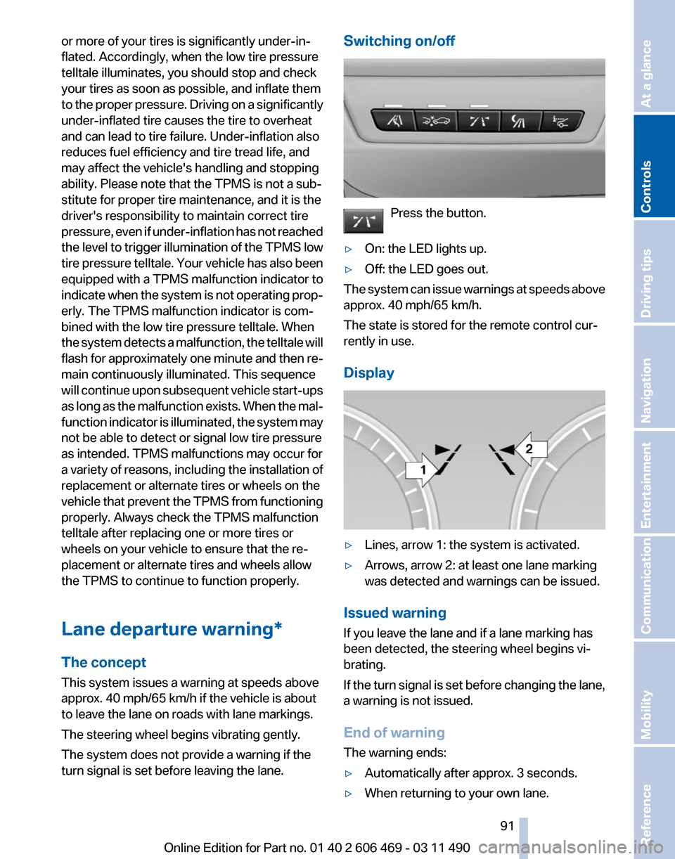
Display ▷
Lines, arrow 1: the system is activated.
▷ Arrows, arrow 2: at least one lane marking
was detected and warnings can be issued.
Issued warning
If you leave the lane and if a lane marking has
been detected, the steering wheel begins vi‐
brating.
If
the turn signal is set before changing the lane,
a warning is not issued.
End of warning
The warning ends:
▷ Automatically after approx. 3 seconds.
▷ When returning to your own lane. Seite 91
91Online Edition for Part no. 01 40 2 606 469 - 03 11 490
Reference Mobility Communication Entertainment Navigation Driving tips
Controls At a glance
Page 95 of 304
Driving stability control systems
Antilock Brake System ABS
ABS
prevents locking of the wheels during brak‐
ing.
The vehicle remains steerable even during full
brake applications, thus increasing active
safety.
ABS is operational every time you start the en‐
gine.
Brake assistant
When you apply the brakes rapidly, this system
automatically produces the maximum braking
force boost. It thus helps to achieve the shortest
possible braking distance during full braking.
This system utilizes all of the benefits provided
by ABS.
Do not reduce the pressure on the brake pedal
for the duration of the full braking.
Adaptive brake assistant
In combination with the Active Cruise Control,
this system ensures that the brakes respond
even more rapidly when braking in critical situa‐
tions. Refer also to Collision warning, refer to
page 108.
Drive-off assistant
This system supports driving away on gradients.
The parking brake is not required.
1. Hold the vehicle in place with the foot brake.
2. Release the foot brake and drive away with‐
out delay.
After the foot brake is released, the vehicle is
held in place for approx. 2 seconds.
Depending on the vehicle load, the vehicle may
roll back slightly. Driving off without delay
After
releasing the foot brake, start driving
without delay, since the drive-off assistant will
not hold the vehicle in place for more than ap‐
prox. 2 seconds and the vehicle will begin rolling
back.◀
DSC Dynamic Stability
Control
The concept
DSC prevents traction loss in the driving wheels
when driving away and accelerating.
DSC also recognizes unstable vehicle condi‐
tions, such as fishtailing or nose-diving. Subject
to physical limits, DSC helps to keep the vehicle
on a steady course by reducing engine speed
and by applying brakes at individual wheels.
Adjust your driving style to the situation
An appropriate driving style is always the
responsibility of the driver.
The laws of physics cannot be repealed, even
with DSC.
Therefore, do not reduce the additional safety
margin by driving in a risky manner.◀
Indicator/warning lamps
The indicator lamp flashes: DSC con‐
trols the drive forces and brake forces.
The indicator lamp lights up: DSC has
failed.
Deactivating DSC: DSC OFF
When DSC is deactivated, driving stability is re‐
duced during acceleration and when driving in
bends.
Stabilizing interventions by the Integral Active
Steering* system are only performed by the rear
axle steering. Seite 95
95Online Edition for Part no. 01 40 2 606 469 - 03 11 490
Reference Mobility Communication Entertainment Navigation Driving tips
Controls At a glance
Page 98 of 304
Dynamic Drive*
The concept
Dynamic Drive reduces the lateral inclination of
the vehicle that occurs during rapid driving in
curves or during quick evasive maneuvers.
Driving stability and driving comfort are in‐
creased
under all driving conditions. The system
utilizes active stabilizer bars on the front and rear
axles that react immediately to all driving situa‐
tions.
Programs
The system offers two different programs.
The programs can be selected via Dynamic Driv‐
ing Control, refer to page 99.
SPORT
Sporty tuning for greater driving agility.
NORMAL
Comfort-oriented tuning for optimal comfort.
Dynamic Damping Control*
The concept
This system reduces undesirable vehicle mo‐
tion when using a dynamic driving style or trav‐
eling on uneven road surfaces.
The system enhances driving dynamics and
comfort as required for the road surface and
driving style.
Programs
The system offers three different programs.
The programs can be selected via Dynamic Driv‐
ing Control, refer to page 99.
SPORT
Consistently sporty control of the shock absorb‐
ers for greater driving agility. NORMAL
Balanced tuning between the COMFORT and
SPORT programs.
COMFORT
Comfort-oriented
tuning of the shock absorbers
for optimal traveling comfort.
Integral Active Steering*
The concept
Integral Active Steering is a combination of Ac‐
tive Steering and rear axle steering.
Active Steering varies the steering angle of the
wheels in relation to the steering wheel move‐
ment as a function of the speed.
At speeds up to approx. 37 mph/60 km/h, e.g.,
in curves, the steering angle is increased, i.e.,
steering becomes more direct.
The rear axle steering acts to increase maneu‐
verability by turning the rear wheels slightly in a
direction opposite to the front wheels.
At higher speeds, the steering angle is increas‐
ingly reduced.
The rear wheels are turned to the same angle as
the front wheels.
In critical situations, Integral Active Steering can
specifically steer the front and rear wheels to
stabilize the vehicle before the driver intervenes,
e.g., when braking where road conditions differ
on the left and right sides of the vehicle.
Initializing
In rare cases, it may become necessary to initi‐
alize the Integral Active Steering.
The warning lamp lights up. A Check
Control message is displayed.
1. With the engine running, turn the steering
wheel
all the way to the left and right several
times in a uniform manner until the warning
lamp disappears. Seite 98
98 Online Edition for Part no. 01 40 2 606 469 - 03 11 490
Driving stability control systems
Page 121 of 304
▷
If the vehicle speed exceeds approx. 6 mph/
10 km/h.
▷ On snow-covered or slippery road surfaces
if necessary.
▷ If doors are open.
A Check Control message is displayed.
Continuing
An interrupted parking procedure can be con‐
tinued if necessary.
Follow
the instructions on the Control Display to
do this.
Switching off
The system can be deactivated as follows:
▷ Press the button. ▷
Switch off the ignition.
Malfunction
A Check Control message is displayed.
The parking assistant failed. Have the system
checked.
System limits Changes to the parking space
Changes to the parking space after it was
measured
are not taken into account by the sys‐
tem.
Therefore, always be alert and ready to inter‐
vene; otherwise, there is the danger of an acci‐
dent occurring.◀
Transporting loads
Loads that extend beyond the perimeter
of the vehicle are not taken into account by the
system during the parking procedure.
Therefore, always be alert and ready to inter‐
vene; otherwise, there is the danger of an acci‐
dent occurring.◀
Curbs
The parking assistant may steer the vehi‐
cle over or onto curbs. Therefore, always be alert and ready to inter‐
vene;
otherwise, the wheels, tires, or the vehicle
may become damaged.◀
No parking assistance
The parking assistant does not provide assis‐
tance in parking.
▷ In tight curves.
Functional limitations
The system may not be fully functional in the
following situations:
▷ When sensors are dirty or iced over.
▷ In heavy fog, rain or snowfall.
▷ On bumpy road surfaces such as gravel
roads.
▷ When leaves or snow has collected in the
parking space.
Limits of ultrasonic measurement
The
detection of objects can reach the physical
limits of ultrasonic measurement, for instance:
▷ With tow bars and trailer hitches.
▷ With thin or wedge-shaped objects.
▷ With elevated, protruding objects such as
ledges or cargo.
▷ With objects with corners and sharp edges.
▷ With objects with a fine surface structure,
such as fences.
The parking assistant may identify parking
spaces that are not suitable for parking.
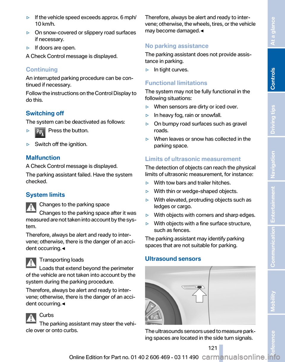
Ultrasound sensors The ultrasounds sensors used to measure park‐
ing spaces are located in the side turn signals.
Seite 121
121Online Edition for Part no. 01 40 2 606 469 - 03 11 490
Reference Mobility Communication Entertainment Navigation Driving tips
Controls At a glance
Page 129 of 304
Switching on
Press any button.
Microfilter/activated-charcoal filter
The microfilter removes dust and pollen from
the incoming air.
The activated-charcoal filter removes gaseous
pollutants from the outside air that enters the
vehicle.
This combined filter should be replaced during
scheduled
maintenance of your vehicle., refer to
page 260
Ventilation
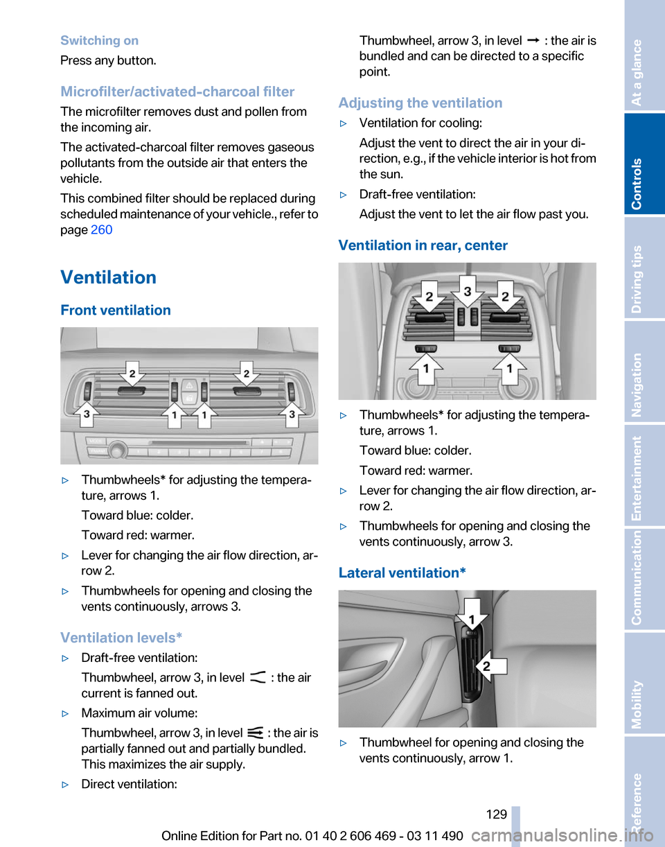
Front ventilation ▷
Thumbwheels* for adjusting the tempera‐
ture, arrows 1.
Toward blue: colder.
Toward red: warmer.
▷ Lever for changing the air flow direction, ar‐
row 2.
▷ Thumbwheels for opening and closing the
vents continuously, arrows 3.
Ventilation levels*
▷ Draft-free ventilation:
Thumbwheel, arrow 3, in level : the air
current is fanned out.
▷ Maximum air volume:
Thumbwheel,
arrow 3, in level : the air is
partially fanned out and partially bundled.
This maximizes the air supply.
▷ Direct ventilation: Thumbwheel, arrow 3, in level :
the air is
bundled and can be directed to a specific
point.
Adjusting the ventilation
▷ Ventilation for cooling:
Adjust the vent to direct the air in your di‐
rection,
e.g., if the vehicle interior is hot from
the sun.
▷ Draft-free ventilation:
Adjust the vent to let the air flow past you.
Ventilation in rear, center ▷
Thumbwheels* for adjusting the tempera‐
ture, arrows 1.
Toward blue: colder.
Toward red: warmer.
▷ Lever for changing the air flow direction, ar‐
row 2.
▷ Thumbwheels for opening and closing the
vents continuously, arrow 3.
Lateral ventilation* ▷
Thumbwheel for opening and closing the
vents continuously, arrow 1.
Seite 129
129Online Edition for Part no. 01 40 2 606 469 - 03 11 490
Reference Mobility Communication Entertainment Navigation Driving tips
Controls At a glance